Copyright
©The Author(s) 2021.
World J Clin Cases. Feb 26, 2021; 9(6): 1367-1378
Published online Feb 26, 2021. doi: 10.12998/wjcc.v9.i6.1367
Published online Feb 26, 2021. doi: 10.12998/wjcc.v9.i6.1367
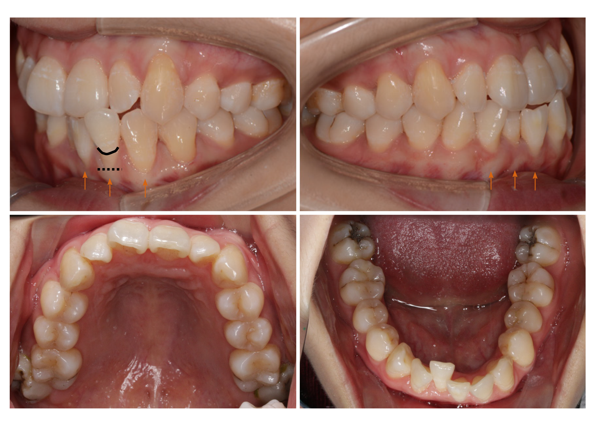
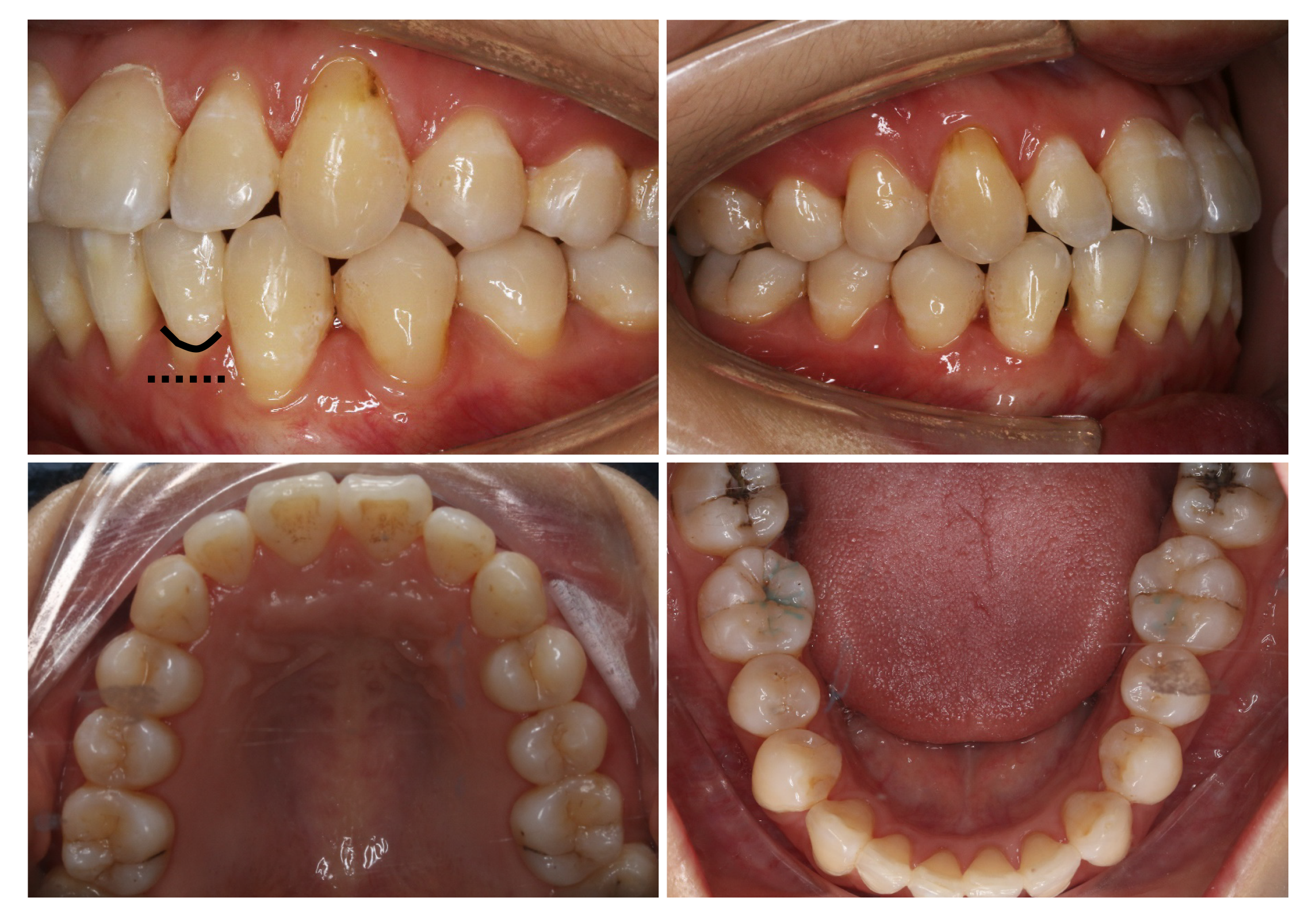
Figure 1 Pre-treatment intraoral photographs: Thin (more delicate, fragile) biotype and root surface exposure caused by apical displacement of the gingival margin past the enamel-cemental junction and prominent roots (orange arrow).
Black line: Enamel-cemental junction at #32. Black dotted line: Gingival/soft tissue margin at #32.
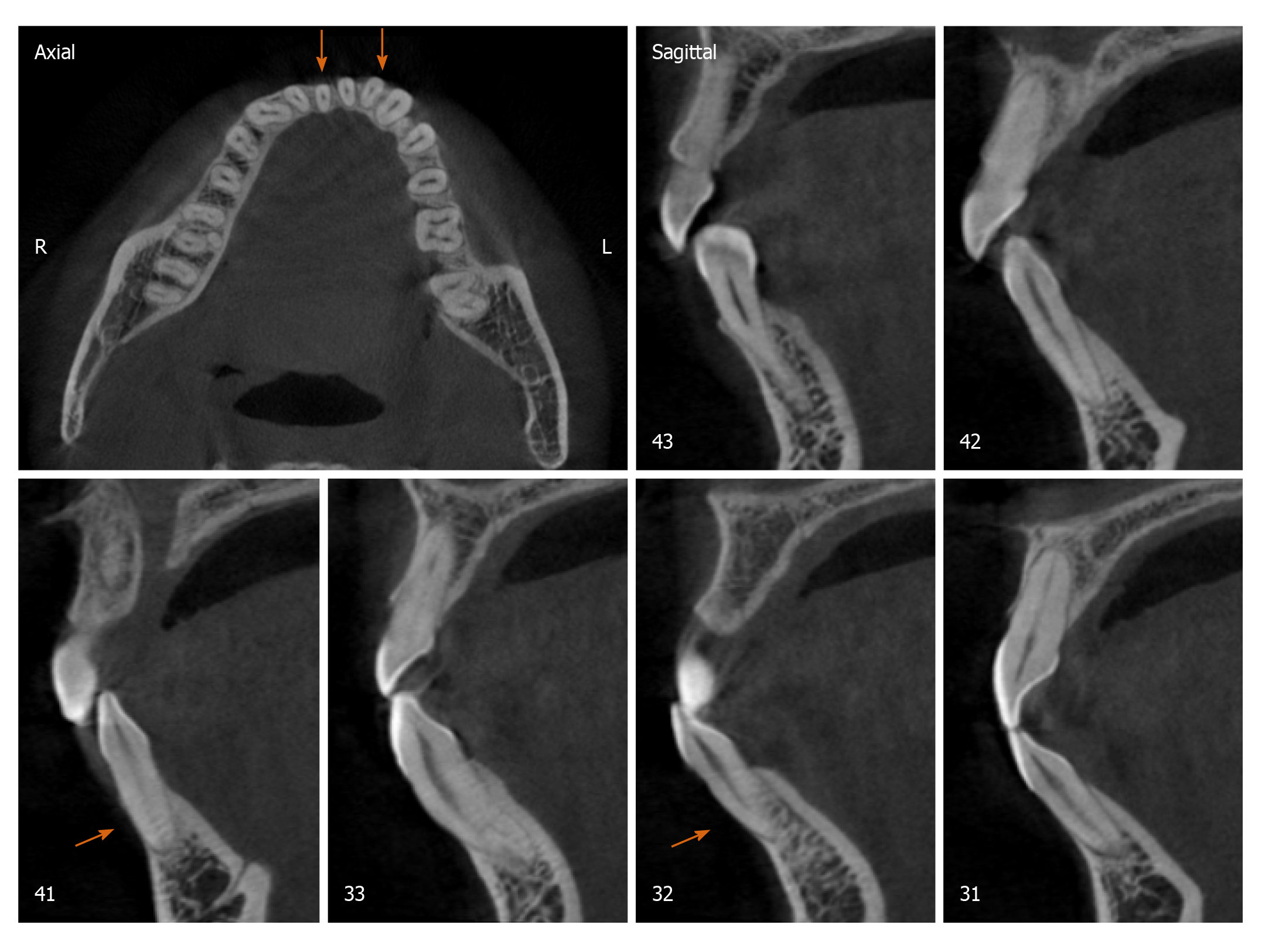
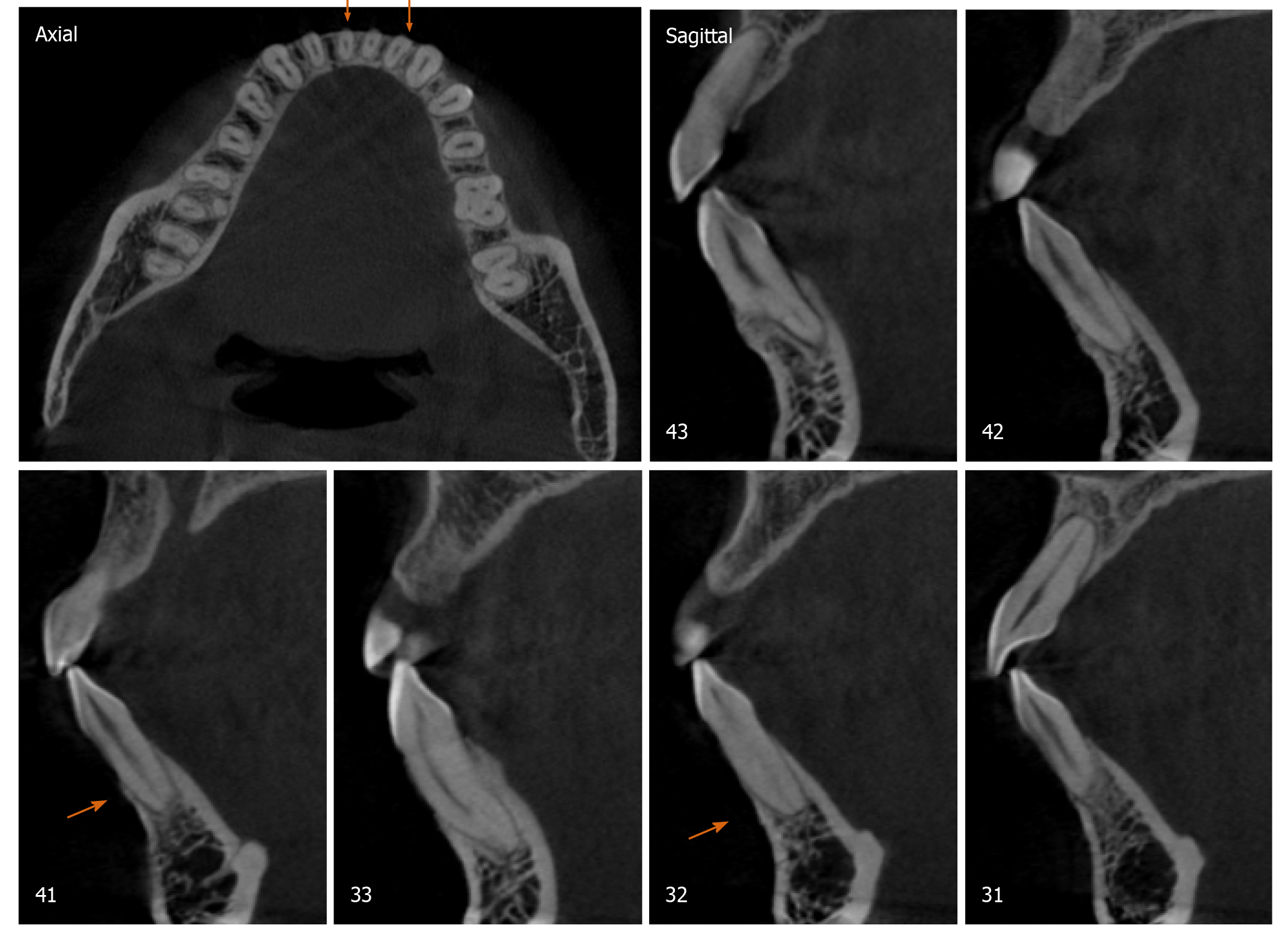
Figure 2 Pre-treatment cone beam computed tomography images.
Orange arrow: Buccal bone plate deficiency at #32 and #41.
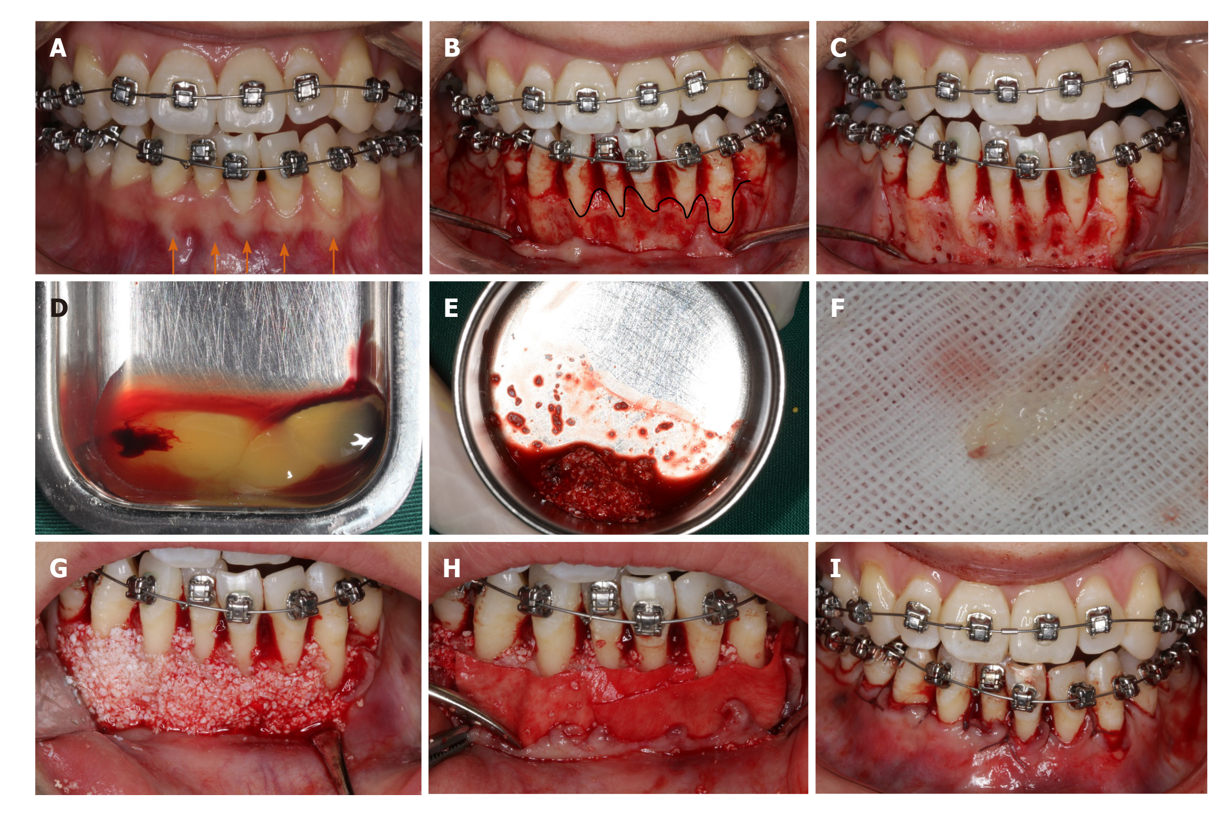
Figure 3 Periodontally accelerated osteogenic orthodontics surgery.
A: Initial photograph with orthodontic appliances; B: Full-thickness envelope flap reflection; C: Cortical punching; D: Preparation of platelet-rich fibrin (PRF); E: Mixing up the Bio-Oss and PRF; F: Self-prepared PRF membrane; G: Placement of a bone graft; H: Coverage of Bio-Gide membrane and PRF membrane; I: Suture. Orange arrow: Prominent roots. Black curved line: Bone margin in the buccal plates.
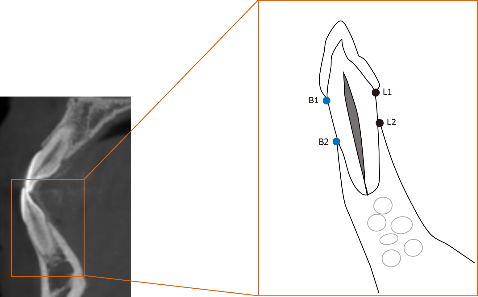
Figure 4 Diagram of a lower anterior tooth in the sagittal section of cone beam computed tomography images.
Buccal height: The distance between B1 and B2. Lingual height: The distance between L1 and L2. B1: Buccal point of the enamel-cemental junction; B2: Buccal top point of the alveolar ridge; L1: Lingual point of the enamel-cemental junction; L2: Buccal top point of the alveolar ridge.
Figure 5 Post-treatment intraoral photographs: Improvements in the periodontium and reduction of gingival recession.
Black line: Enamel-cemental junction at #32. Black dotted line: Gingival/soft tissue margin at #32.
Figure 6 Post-treatment cone beam computed tomography images.
Orange arrow: Bone augmentation at #32 and #41.
- Citation: Xu M, Sun XY, Xu JG. Periodontally accelerated osteogenic orthodontics with platelet-rich fibrin in an adult patient with periodontal disease: A case report and review of literature. World J Clin Cases 2021; 9(6): 1367-1378
- URL: https://www.wjgnet.com/2307-8960/full/v9/i6/1367.htm
- DOI: https://dx.doi.org/10.12998/wjcc.v9.i6.1367


