Copyright
©The Author(s) 2021.
World J Clin Cases. Nov 16, 2021; 9(32): 10033-10039
Published online Nov 16, 2021. doi: 10.12998/wjcc.v9.i32.10033
Published online Nov 16, 2021. doi: 10.12998/wjcc.v9.i32.10033
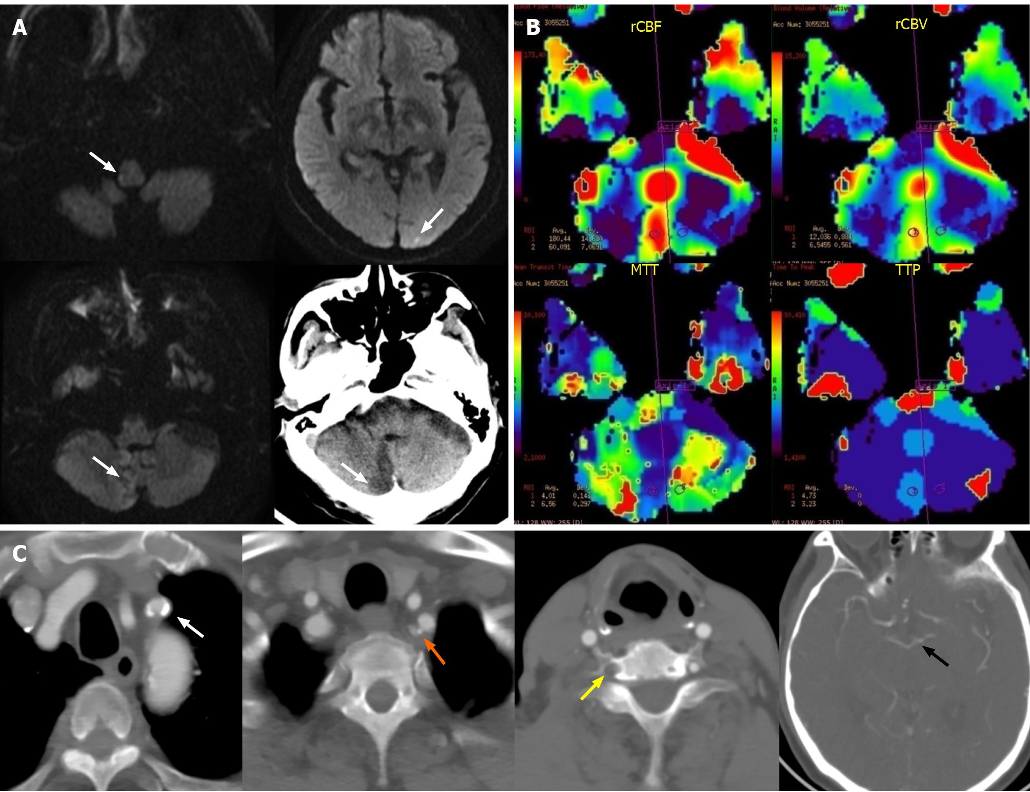
Figure 1 Imaging evaluations of brain before subclavian artery stenting.
A: Magnetic resonance (MR) diffusion-weighted imaging and non-contrast computed tomography scan showed the coexistence of acute and subacute infarctions in cerebellum, medulla oblongata and occipital lobe (white arrow); B: MR-perfusion-weighted imaging showed that there was no significant difference in relative cerebral blood flow, relative cerebral blood volume, mean transit time and time to peak between bilateral cerebellar hemispheres except the infarct core; C: Computed tomography angiography showed the calcified plaques lead to the stenosis of proximal left subclavian artery (white arrow), stenosis at origin of the left vertebral artery (VA) (orange arrow), the occlusion of right VA (yellow arrow), and the bilateral posterior communicating arteries were not opening (black arrow point to the top of basilar artery).
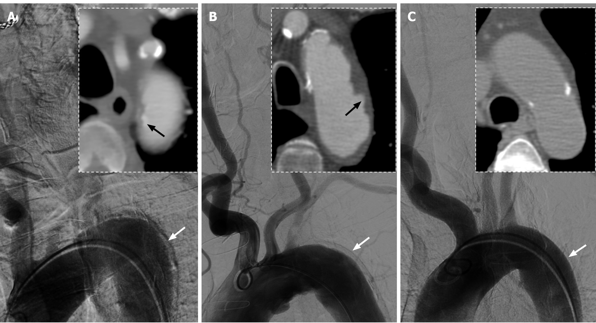
Figure 2 Comparison of aortic arch images between three male patients with anteroposterior views on digital subtraction angiography and axial views on computed tomography angiography.
A: Images of this present case showed a significant artifact on lateral wall of descending aorta (white arrow) and displacement of aortic intimal calcification (black arrow); B: Images of the second patient, aged 79-years-old, showed a similar artifact (white arrow) and penetrating atherosclerotic ulcers (black arrow); C: Images of the third patient, aged 64-years-old, showed mild atherosclerosis on the aortic wall without obvious artifact (white arrow).
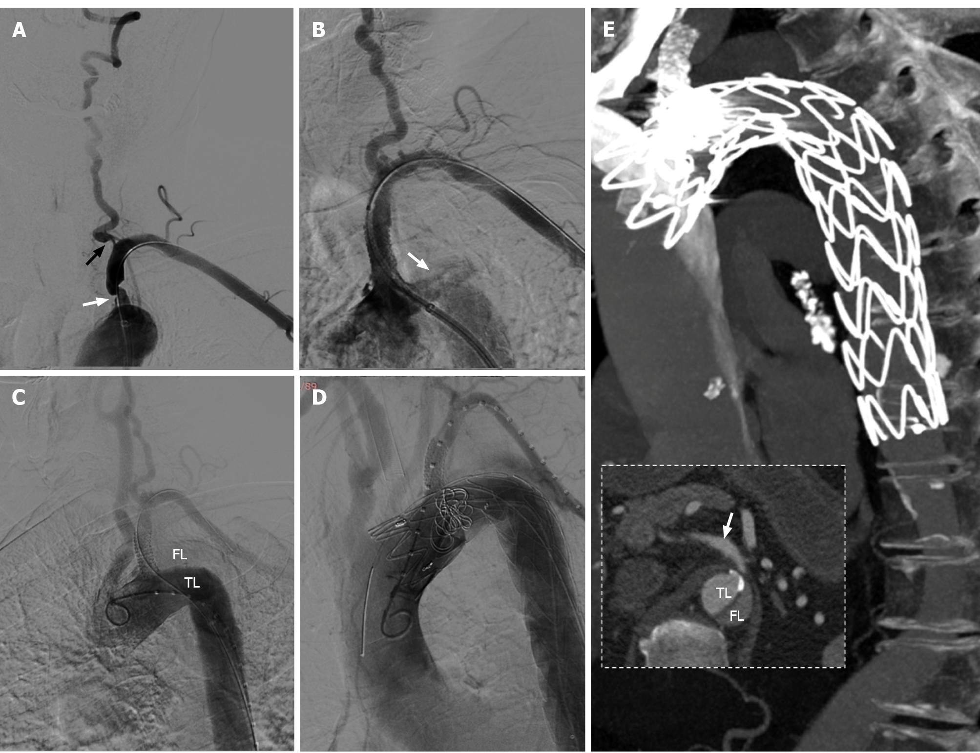
Figure 3 The procedures of subclavian artery stenting for stenosis and thoracic endovascular aortic repair for aortic dissection.
A: Severe stenosis of the proximal left subclavian artery (LSA) (white arrow) and the ostium of ipsilateral vertebral artery (black arrow) were presented in digital subtraction angiography; B: Contrast entering the aortic wall (white arrow) after a balloon expandable stent implanted into LSA; C: The true lumen and false lumen (FL) could be clearly displayed in angiogram of aortic dissection, and the origin of dissection was identified at the proximal edge of stent; D: Chimney technique was used in thoracic endovascular aortic repair; E: Two-week computed tomography angiography (CTA) follow-up, there was no significant contrast enter into the FL, and the distal end of aortic dissection was at least below the bifurcation point of celiac trunk (white arrow, CTA failed to scan the whole dissection).
- Citation: Zhang Y, Wang JW, Jin G, Liang B, Li X, Yang YT, Zhan QL. Focal intramural hematoma as a potential pitfall for iatrogenic aortic dissection during subclavian artery stenting: A case report. World J Clin Cases 2021; 9(32): 10033-10039
- URL: https://www.wjgnet.com/2307-8960/full/v9/i32/10033.htm
- DOI: https://dx.doi.org/10.12998/wjcc.v9.i32.10033


