Copyright
©The Author(s) 2021.
World J Clin Cases. Aug 6, 2021; 9(22): 6343-6356
Published online Aug 6, 2021. doi: 10.12998/wjcc.v9.i22.6343
Published online Aug 6, 2021. doi: 10.12998/wjcc.v9.i22.6343
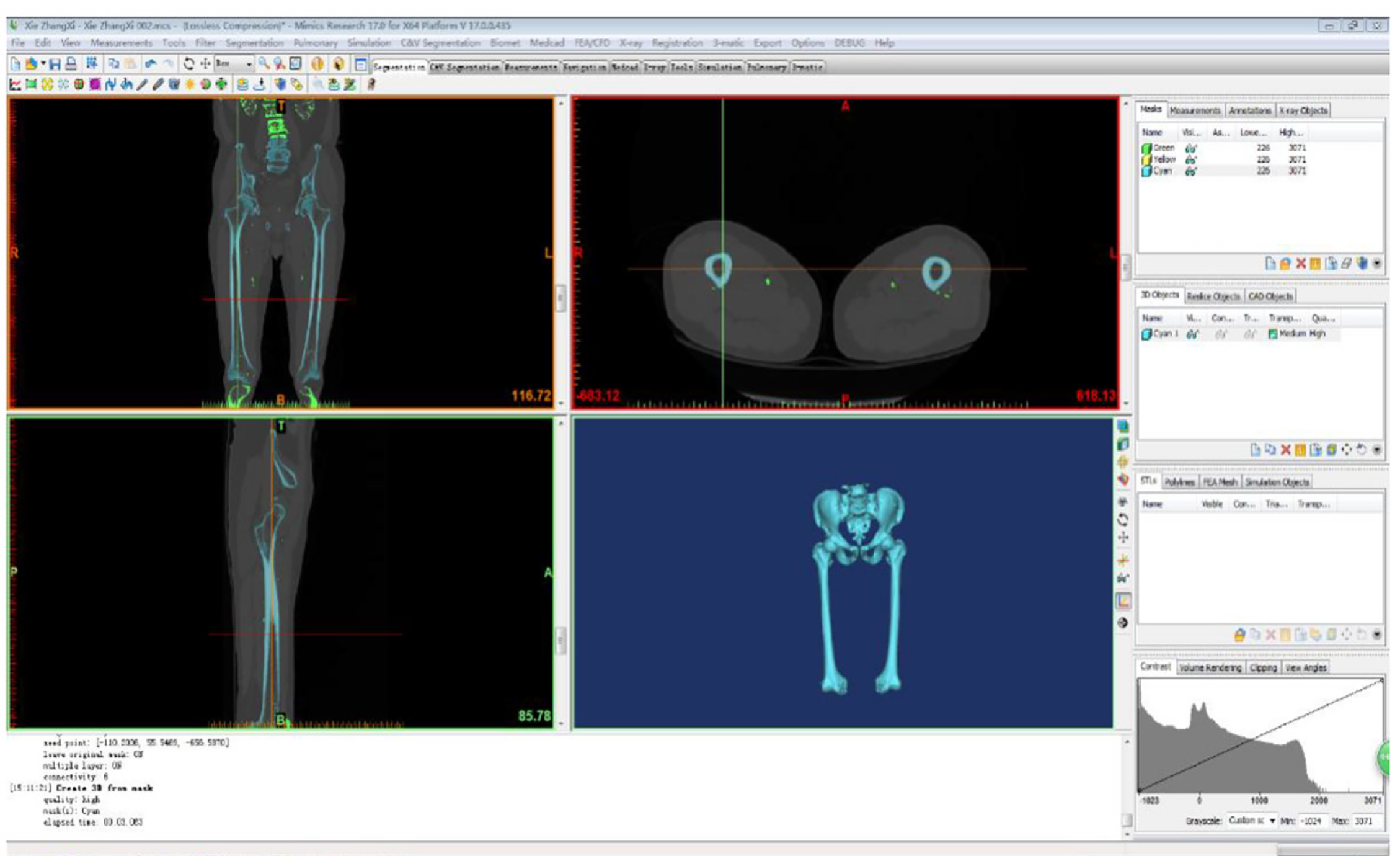
Figure 1 Geometric model of the femur.
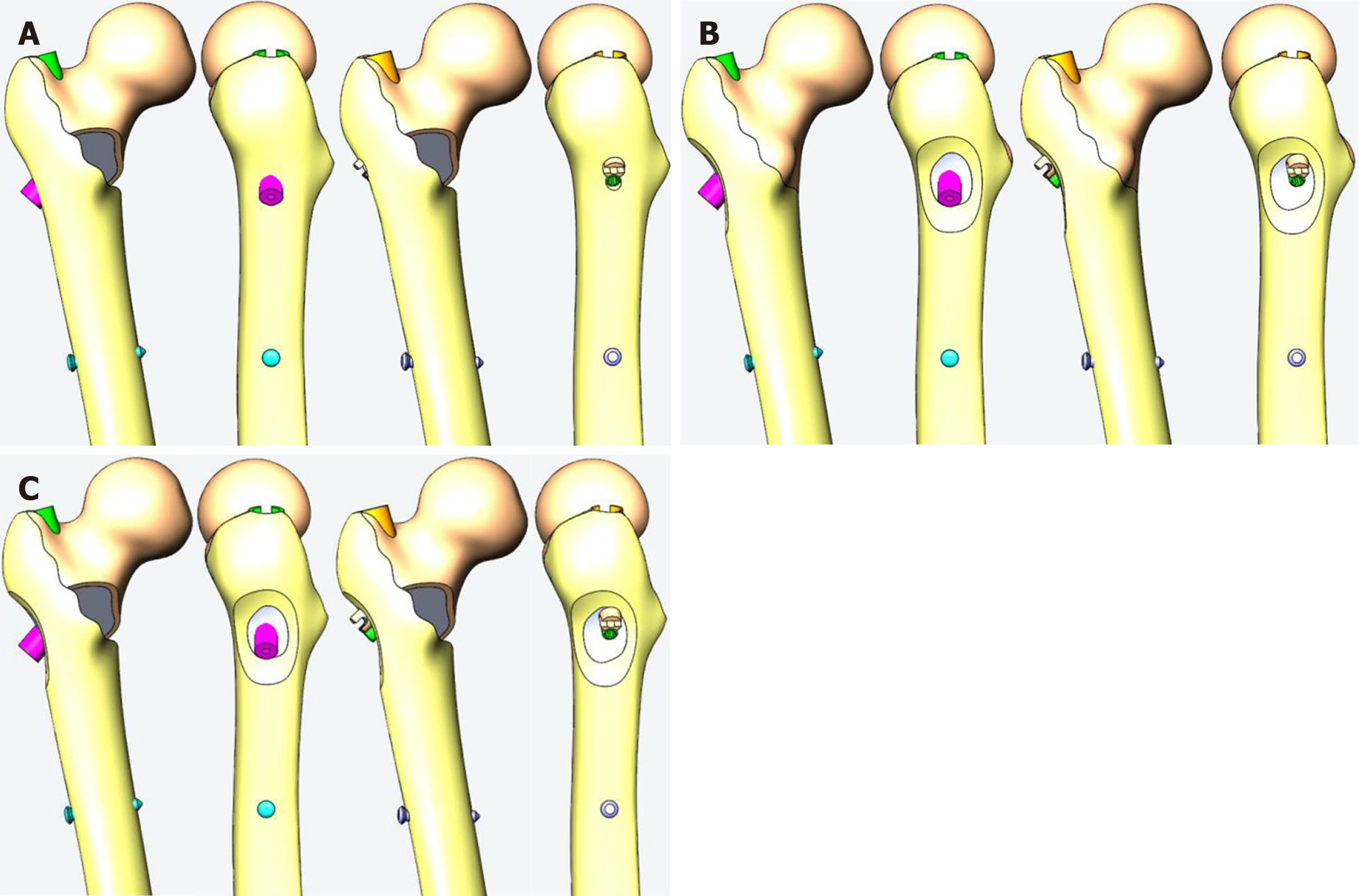
Figure 2 Medial injury models in the 3D-model.
A: Medial defect model; B: Lateral defect model; C: Lateral and medial defect model.
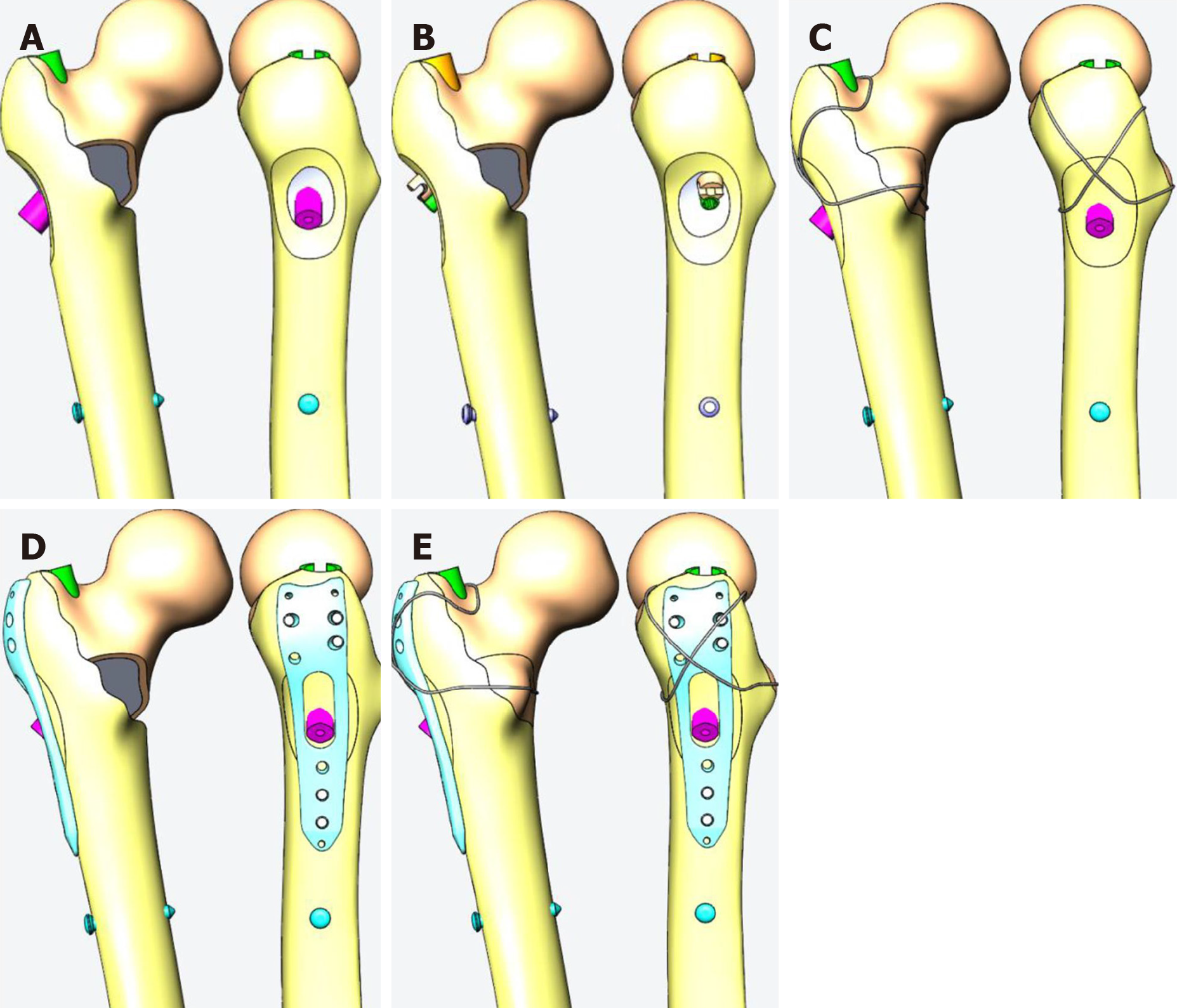
Figure 3 Fixation models in the 3D model.
A: Proximal femoral anti-rotation intramedullary nail (PFNA) representing intramedullary fixation model 1; B: Interlocking intramedullary nails model 2; C: PFNA and steel wire model 3; D: PFNA and interlocking plate model 4; E: PFNA with wire and plate model 5.
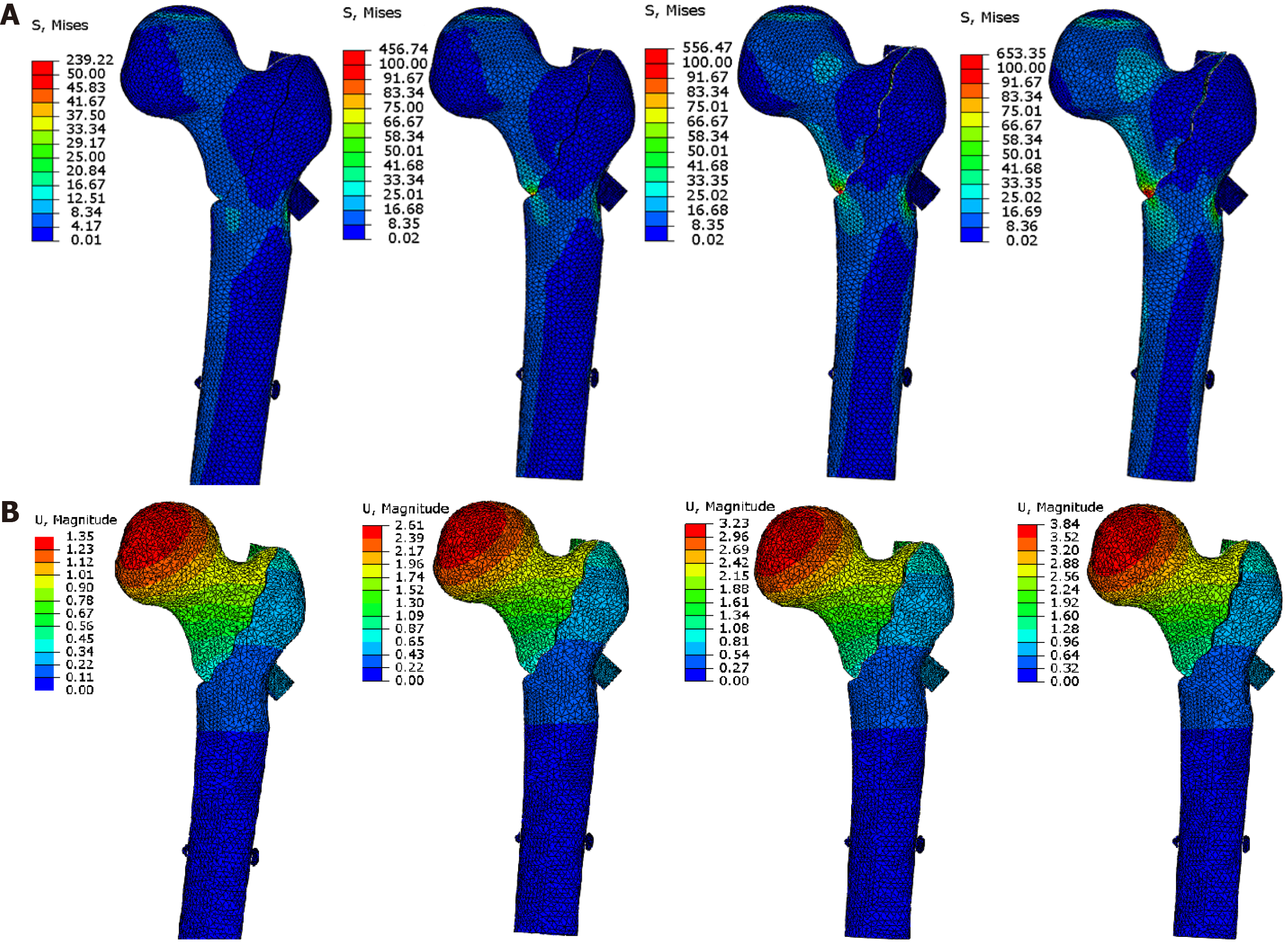
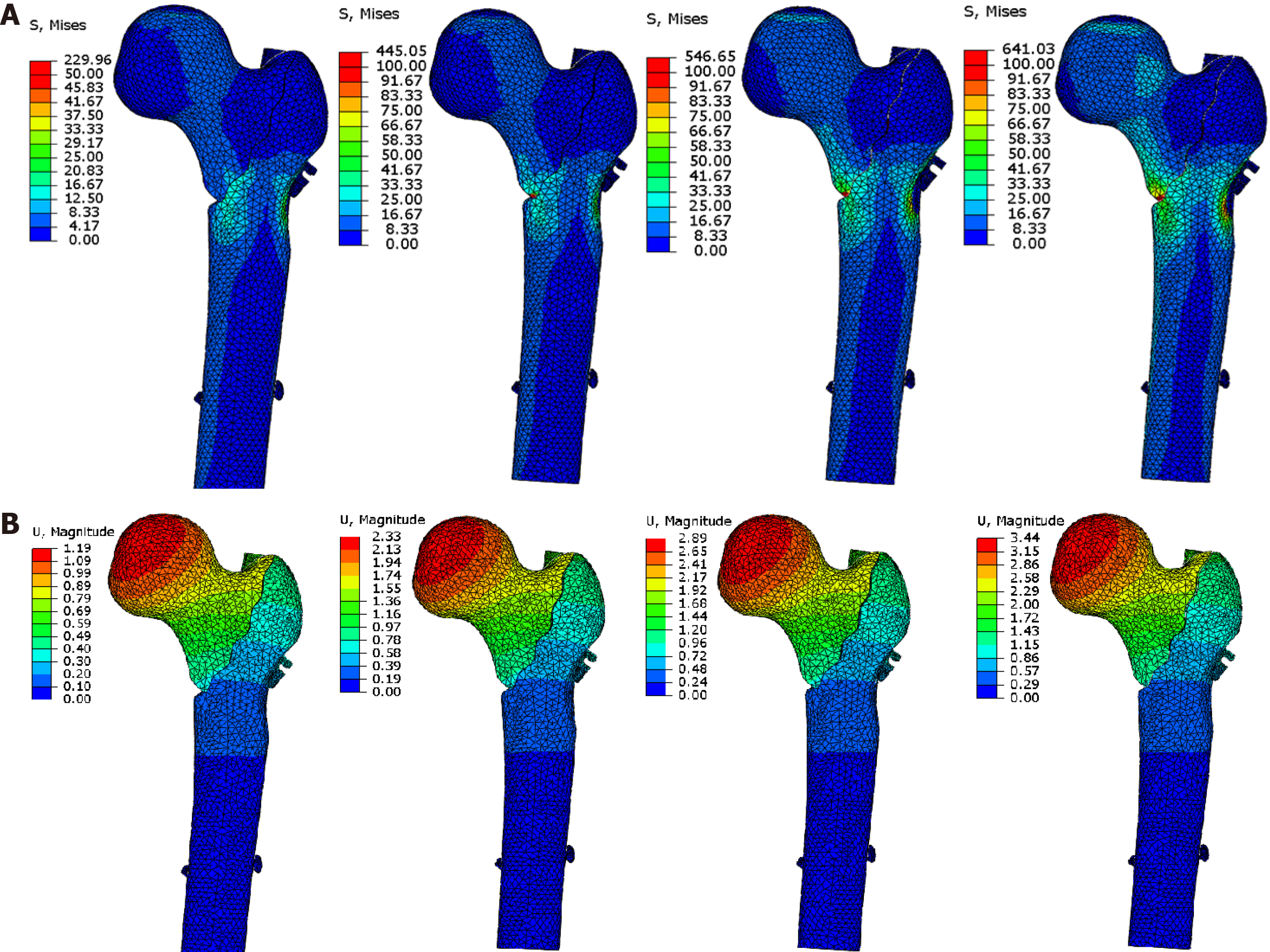
Figure 4 Stress distribution and displacement distribution under different loading modes when lateral and medial defects were fixed with proximal femoral anti-rotation intramedullary nail.
A: Von Mises stress distribution map when lateral and medial defects were fixed with proximal femoral anti-rotation intramedullary nail (PFNA); B: Displacement distribution when lateral and medial defects were fixed with PFNA.
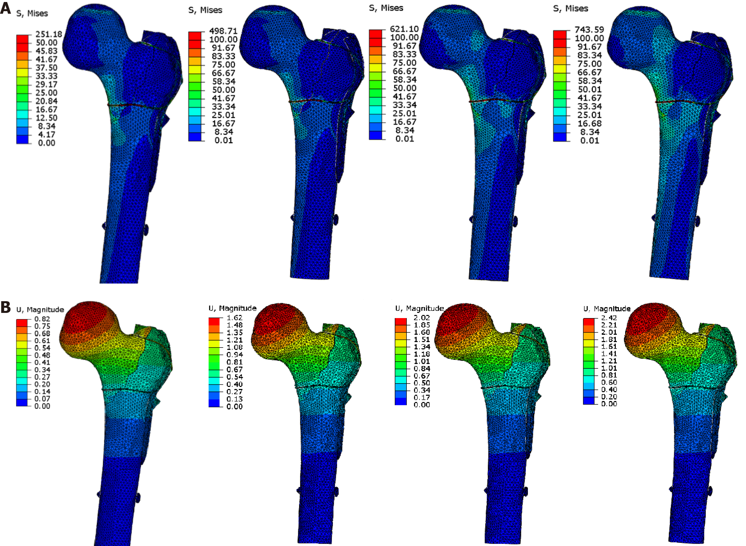
Figure 5 Stress distribution and displacement distribution under different loading modes when lateral and medial defects were fixed with integrated dual-screw fixation.
A: Von Mises stress distribution map when lateral and medial defects were fixed with Integrated dual-screw fixation (ITN); B: Displacement distribution when lateral and medial defects were fixed with ITN.
Figure 6 Stress distribution and displacement distribution under different loading modes when lateral and medial defects were fixed with proximal femoral anti-rotation intramedullary nail steel wire and lateral wall protection plate.
A: Von Mises stress distribution map when lateral and medial defects were fixed with proximal femoral anti-rotation intramedullary nail (PFNA), steel wire, and lateral wall protection plate; B: Displacement distribution when lateral and medial defects were fixed with PFNA, steel wire, and lateral wall protection plate.
- Citation: Mu JX, Xiang SY, Ma QY, Gu HL. Selection of internal fixation method for femoral intertrochanteric fractures using a finite element method. World J Clin Cases 2021; 9(22): 6343-6356
- URL: https://www.wjgnet.com/2307-8960/full/v9/i22/6343.htm
- DOI: https://dx.doi.org/10.12998/wjcc.v9.i22.6343


