Copyright
©The Author(s) 2019.
World J Clin Cases. May 26, 2019; 7(10): 1234-1241
Published online May 26, 2019. doi: 10.12998/wjcc.v7.i10.1234
Published online May 26, 2019. doi: 10.12998/wjcc.v7.i10.1234
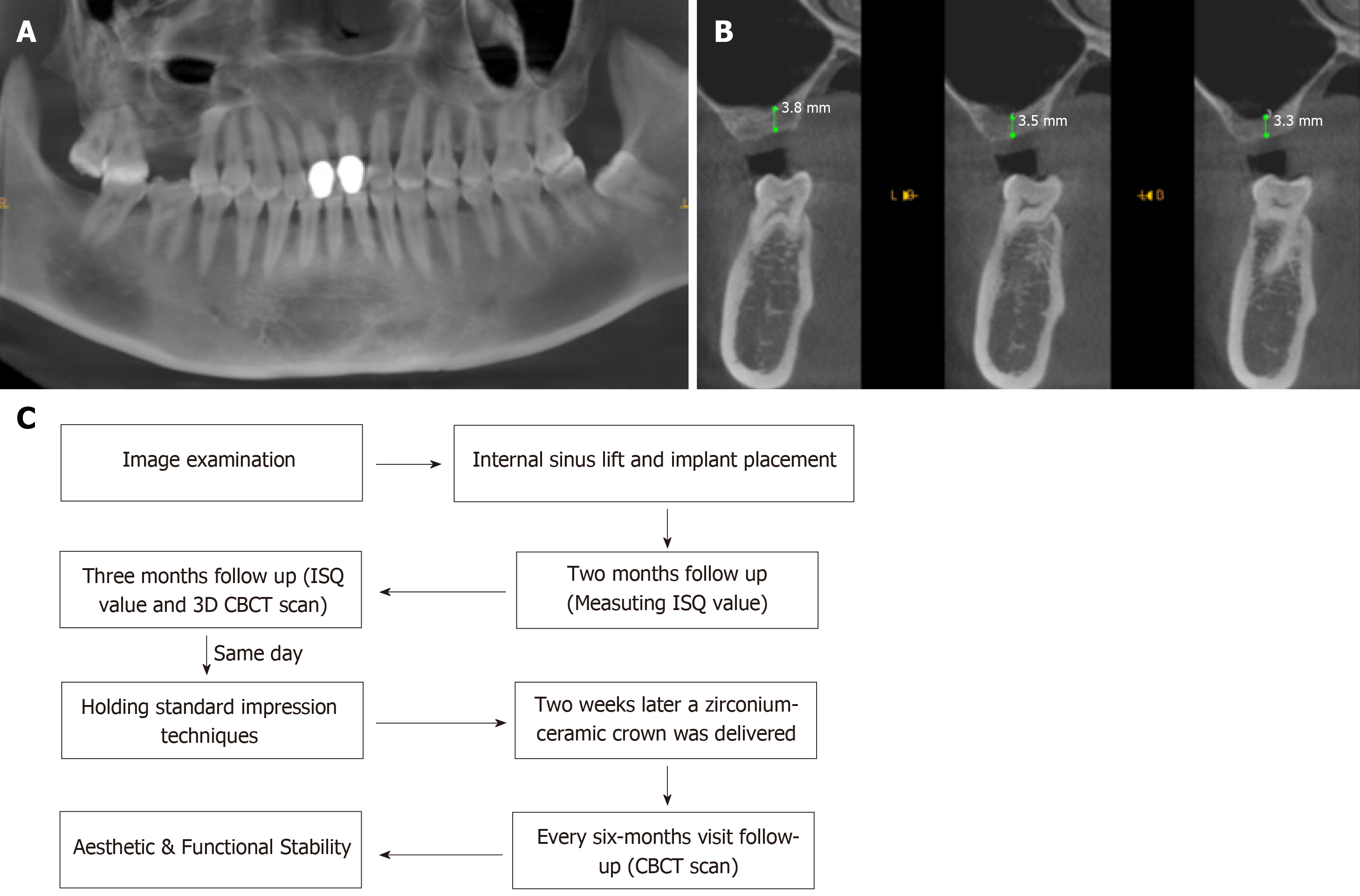
Figure 1 Preoperative cone-beam computed tomography.
A: Sagittal cone-beam computed tomography (CBCT) image showing the mesio-distal dimensions; B: Coronal CBCT image showing a 3.5 mm height of #16; C: Flow chart timeline of the treatment plan. CBCT: Cone-beam computed tomography; ISQ: Implant stability quotient.
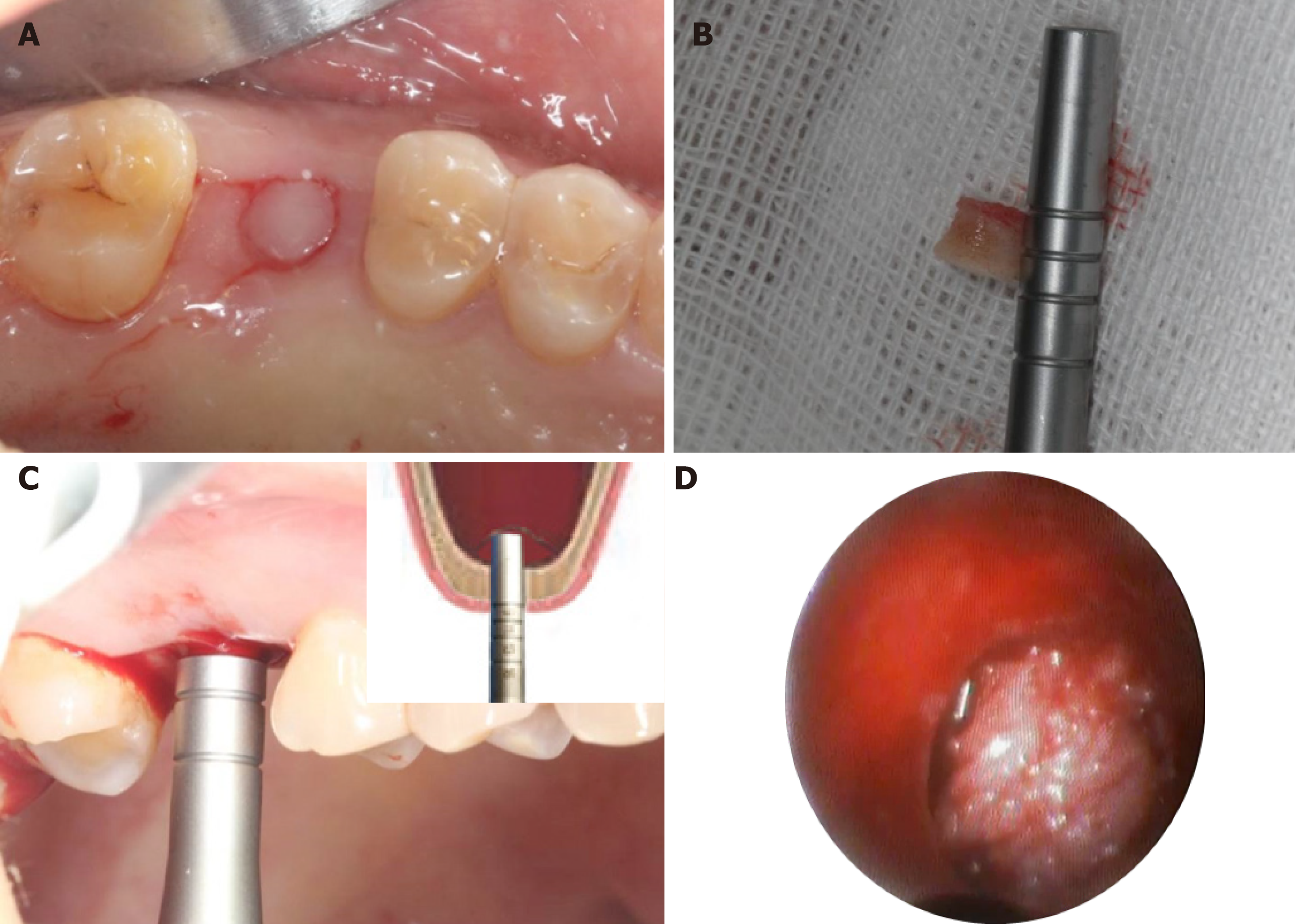
Figure 2 Intraoperative illustrations to explain each step of the surgery.
A: Establishment of a punch incision; B: Full-thickness keratinized gingival punch removal; C: Gentle elevation of the Schneiderian membrane till approximately 7 mm; D: An endoscope was used to monitor the maxillary sinus membrane.
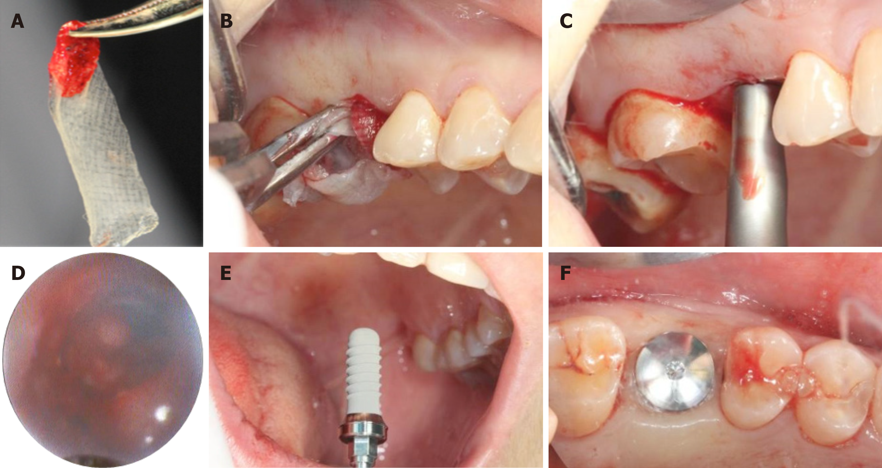
Figure 3 Methodological illustration of platelet-rich fibrin establishment.
A: Three platelet-rich fibrin (PRF) clots were compressed between sterile dry gauze; B: Established PRF membranes were filled into the primary elevated sinus floor; C: The sinus membrane was secondary up-elevated to reach a 12 mm total height; D: Endoscopic evaluation on PRF and sinus floor membranes by nasal breathing exercises; E: Installation of an implant (⌀ 4.8 mm × 12 mm, Straumann, Switzerland); F: Placement of a suitable healing cap.
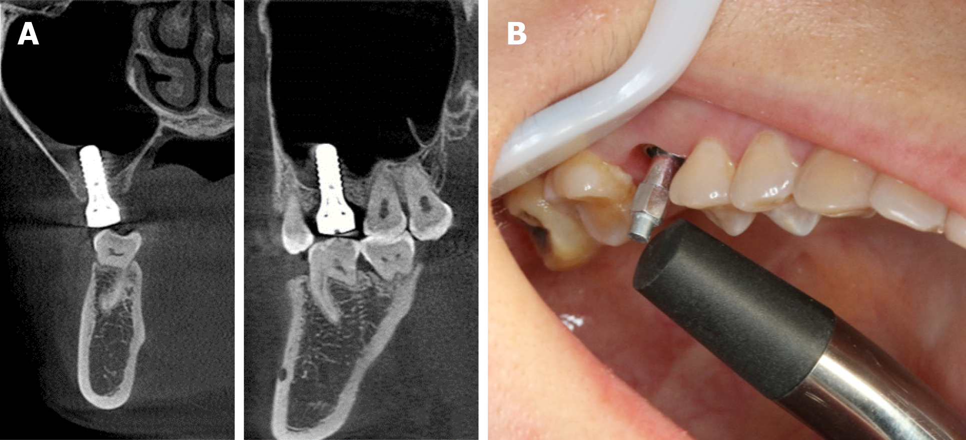
Figure 4 Assessments at 2 mo after surgery.
A: Coronal and sagittal cone-beam computed tomography images showing the uneventful osseointegration around the implant; B: Mean implant stability quotient value was 57.8.
Figure 5 Cone-beam computed tomography images obtained at the 3-mo follow-up.
A: Coronal cone-beam computed tomography (CBCT) image showing the gained bone height around the implant; B: 3D CBCT image showing the gained bone from the buccal side; C: Another intra-maxillary 3D CBCT image showing the bone formation level at the same time.
Figure 6 Intraoral photos to illustrate the standard impression techniques.
A: Suitable abutment was fitted; B: Impression cap and liners were positioned for accurate impression results; C: Final impression with analog in place for the following cast procedures.
Figure 7 A zirconium-ceramic crown was delivered.
Final result was satisfactory. A: A painless 35 N torque was added to put the abutment in place; B: Occlusal view of the final prosthesis in place; C: Buccal view of the final prosthesis in place.
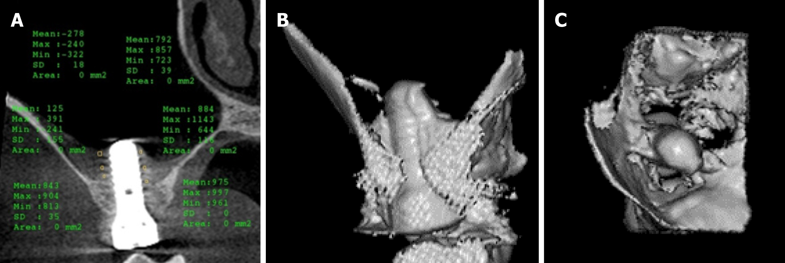
Figure 8 Cone-beam computed tomography images obtained at the 6-mo follow-up.
A: Increased bone level and implant stability quotient values were gained around the implant; B: 3D cone-beam computed tomography image showing positive and successful results; C: Intra-maxillary bone formation showed stable and promising future results.
- Citation: Mudalal M, Sun XL, Li X, Fang J, Qi ML, Wang J, Du LY, Zhou YM. Minimally invasive endoscopic maxillary sinus lifting and immediate implant placement: A case report. World J Clin Cases 2019; 7(10): 1234-1241
- URL: https://www.wjgnet.com/2307-8960/full/v7/i10/1234.htm
- DOI: https://dx.doi.org/10.12998/wjcc.v7.i10.1234


