Copyright
©The Author(s) 2024.
World J Clin Cases. Mar 26, 2024; 12(9): 1578-1584
Published online Mar 26, 2024. doi: 10.12998/wjcc.v12.i9.1578
Published online Mar 26, 2024. doi: 10.12998/wjcc.v12.i9.1578
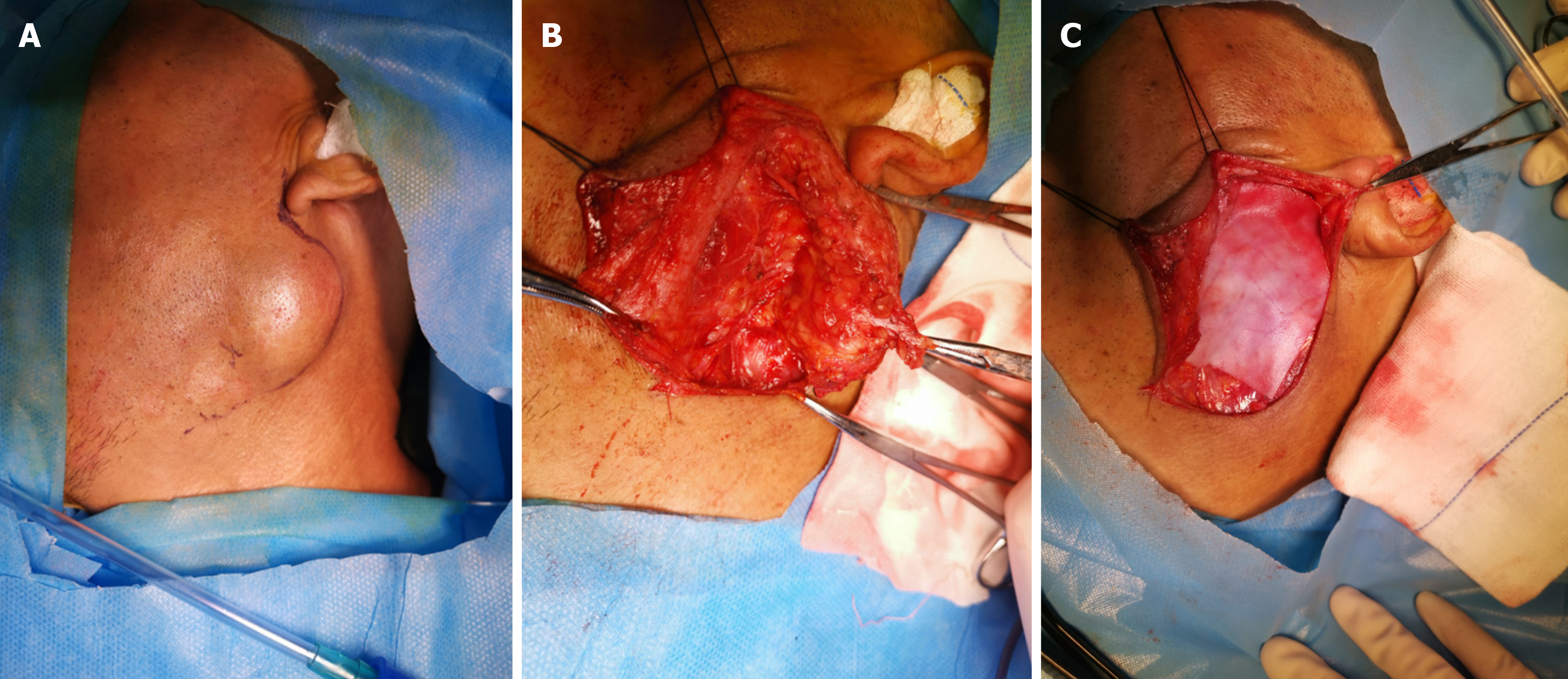
Figure 1 The drainage tube was placed above the patch according to the product guidelines for patients with an implanted tissue patch.
A: Diagram B of the surgical incision; B: For superficial parotid lobectomy behind nerve exposure; C: Acellular dermal matrix after implantation.
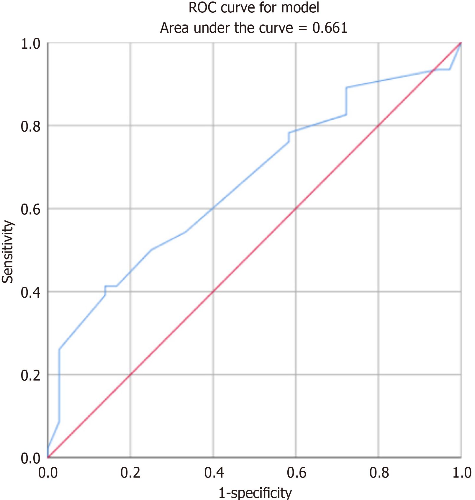
Figure 2 Diameter of surgically resected sample and receiver operating characteristic curve with Frey sign.
ROC: Receiver operating characteristic.
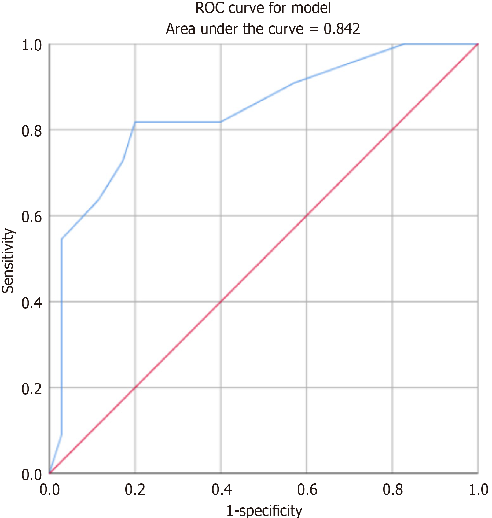
Figure 3 Frey sign occurrence time and receiver operating characteristic curve after acellular dermal matrix implantation.
ROC: Receiver operating characteristic.
- Citation: Chai XD, Jiang H, Tang LL, Zhang J, Yue LF. Factors influencing Frey syndrome after parotidectomy with acellular dermal matrix. World J Clin Cases 2024; 12(9): 1578-1584
- URL: https://www.wjgnet.com/2307-8960/full/v12/i9/1578.htm
- DOI: https://dx.doi.org/10.12998/wjcc.v12.i9.1578


