Copyright
©The Author(s) 2023.
World J Clin Cases. Mar 6, 2023; 11(7): 1593-1599
Published online Mar 6, 2023. doi: 10.12998/wjcc.v11.i7.1593
Published online Mar 6, 2023. doi: 10.12998/wjcc.v11.i7.1593
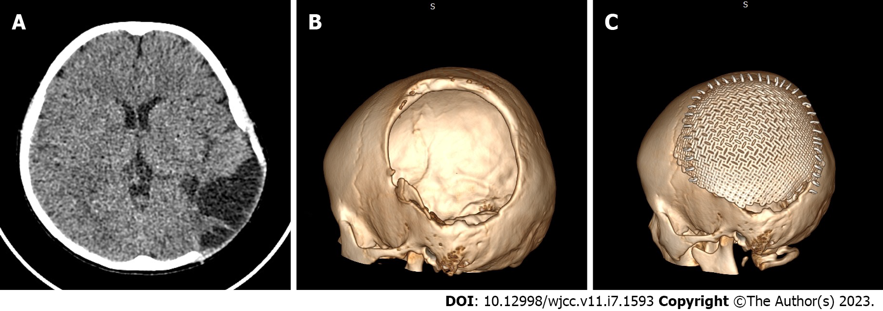
Figure 1 Computerized tomography images before and after first cranioplasty.
A: Axial computerized tomography (CT) image displayed the left temporo-parieto-occipital skull with local encephalocele; B: Three-dimensional (3-D) CT reconstruction revealing a 10 cm × 8 cm defect of the left temporo-parieto-occipital skull; C: 3-D CT reconstruction after first cranioplasty displaying an intact and ideally positioned prosthesis.
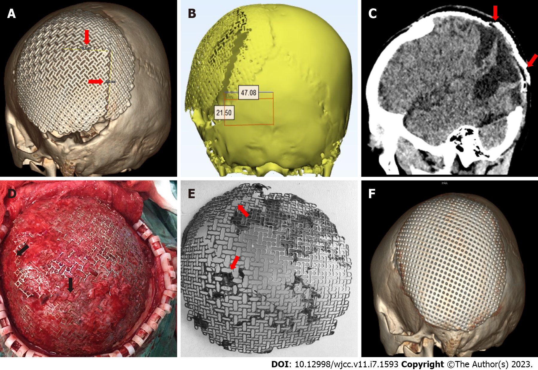
Figure 2 Images before, during, and after second cranioplasty.
A: Three-dimensional (3-D) computerized tomography (CT) reconstruction before the second cranioplasty displayed a reverse “L”-shaped fracture of the titanium mesh prosthesis; B and C: CT at the coronal and sagittal plane revealed the prosthetic fissure (red arrow); D: Intraoperative photograph showing the clear edge of the titanium mesh fracture; E: The fractured titanium mesh was removed during the second cranioplasty; F: 3-D CT reconstruction after the second cranioplasty disclosed an intact and ideally positioned implant.
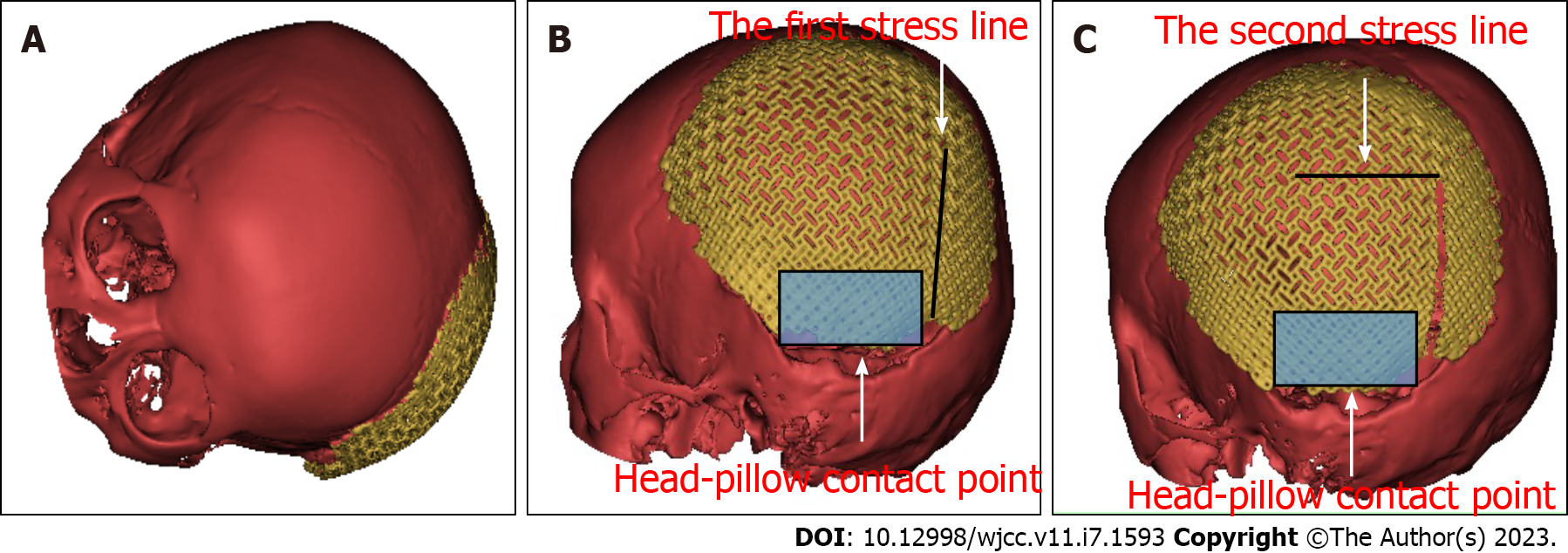
Figure 3 Three-dimensional model of skull-implant.
A: Three-dimensional (3-D) printed skull model rotated on a horizontal plate simulated head rotation on a pillow; B and C: Force analysis model of head rotation on a pillow.
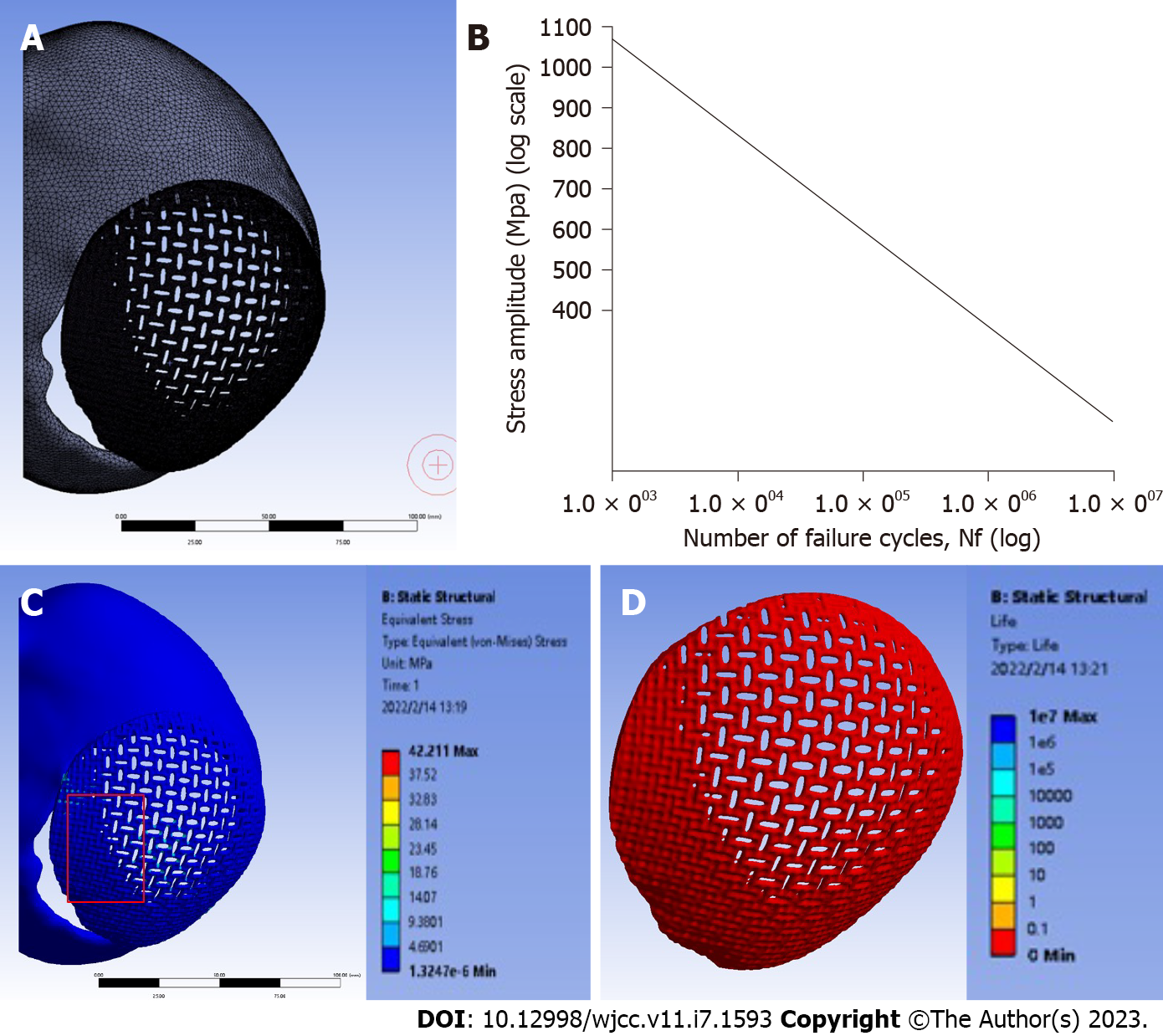
Figure 4 Finite element analysis model.
A: Model of skull-implanted mesh; B: Stress life fatigue curve of the skull-implant model; C: Stress distribution analysis of the skull-implant model in contact with a pillow; D: Fatigue behavior analysis of the titanium mesh.
- Citation: Zhang R, Gao Z, Zhu YJ, Wang XF, Wang G, He JP. Spontaneous fracture of a titanium mesh cranioplasty implant in a child: A case report. World J Clin Cases 2023; 11(7): 1593-1599
- URL: https://www.wjgnet.com/2307-8960/full/v11/i7/1593.htm
- DOI: https://dx.doi.org/10.12998/wjcc.v11.i7.1593


