Copyright
©The Author(s) 2021.
World J Clin Cases. Dec 26, 2021; 9(36): 11425-11436
Published online Dec 26, 2021. doi: 10.12998/wjcc.v9.i36.11425
Published online Dec 26, 2021. doi: 10.12998/wjcc.v9.i36.11425
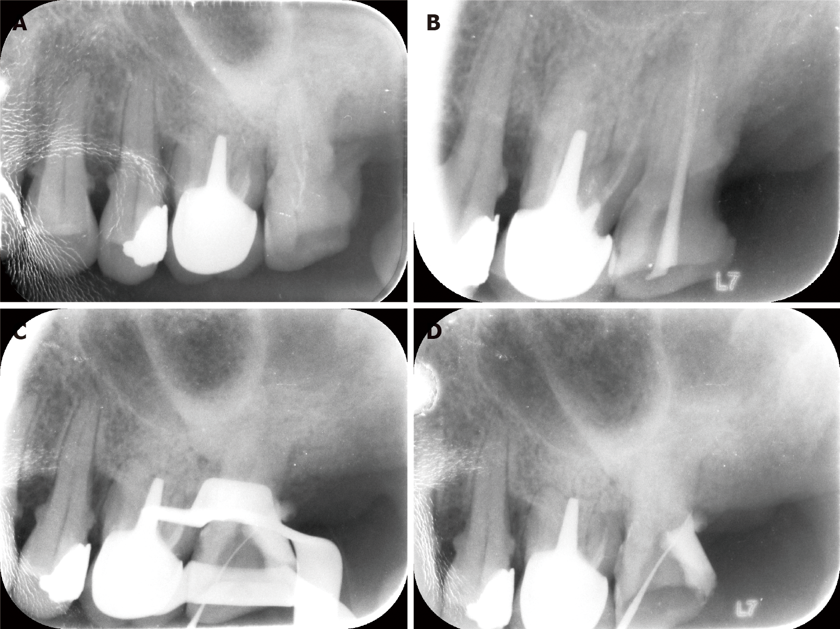
Figure 1 The maxillary left second molar before retreatment and preliminary preparations with the conventional method.
A: Radiographic image of the tooth before retreatment; B: Retreatment of the mesial and palatal roots of the tooth has smoothly reached the working length; C: Even after 2.5 h, the distal root has not been found under a microscope; D: Treatment using conventional methods resulted in a small perforation in the pulpal floor.
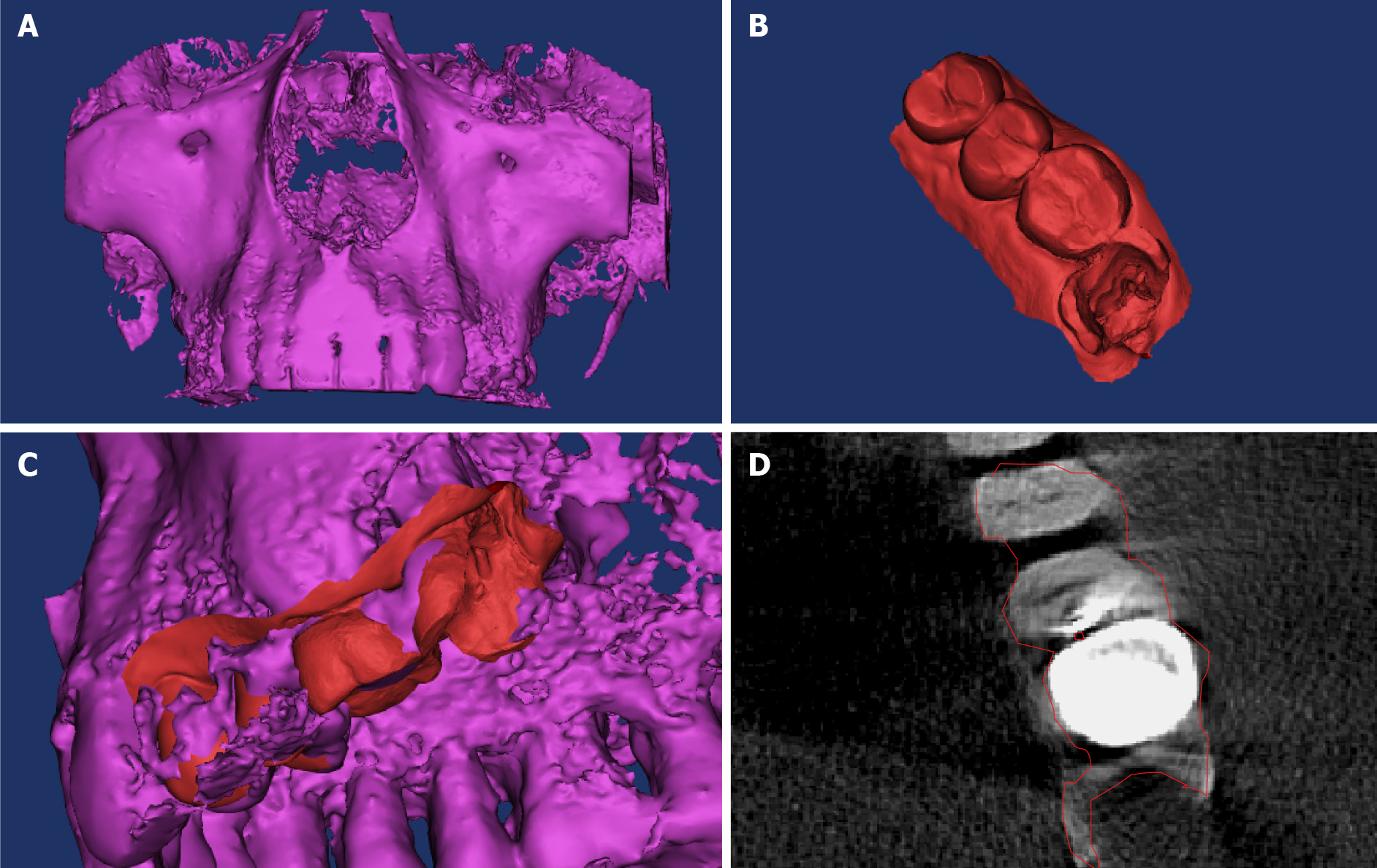
Figure 2 Establishment of a three-dimensional model of the dental hard tissue and root canal.
A: Cone-beam computed tomography (CBCT) of the patient’s maxillary teeth; B: The dentition was impressed on the working area using a three-dimensional (3D) scanner; C and D: The integrated 3D model. Red and purple parts represent the digital impression of the dentition and CBCT data, respectively.
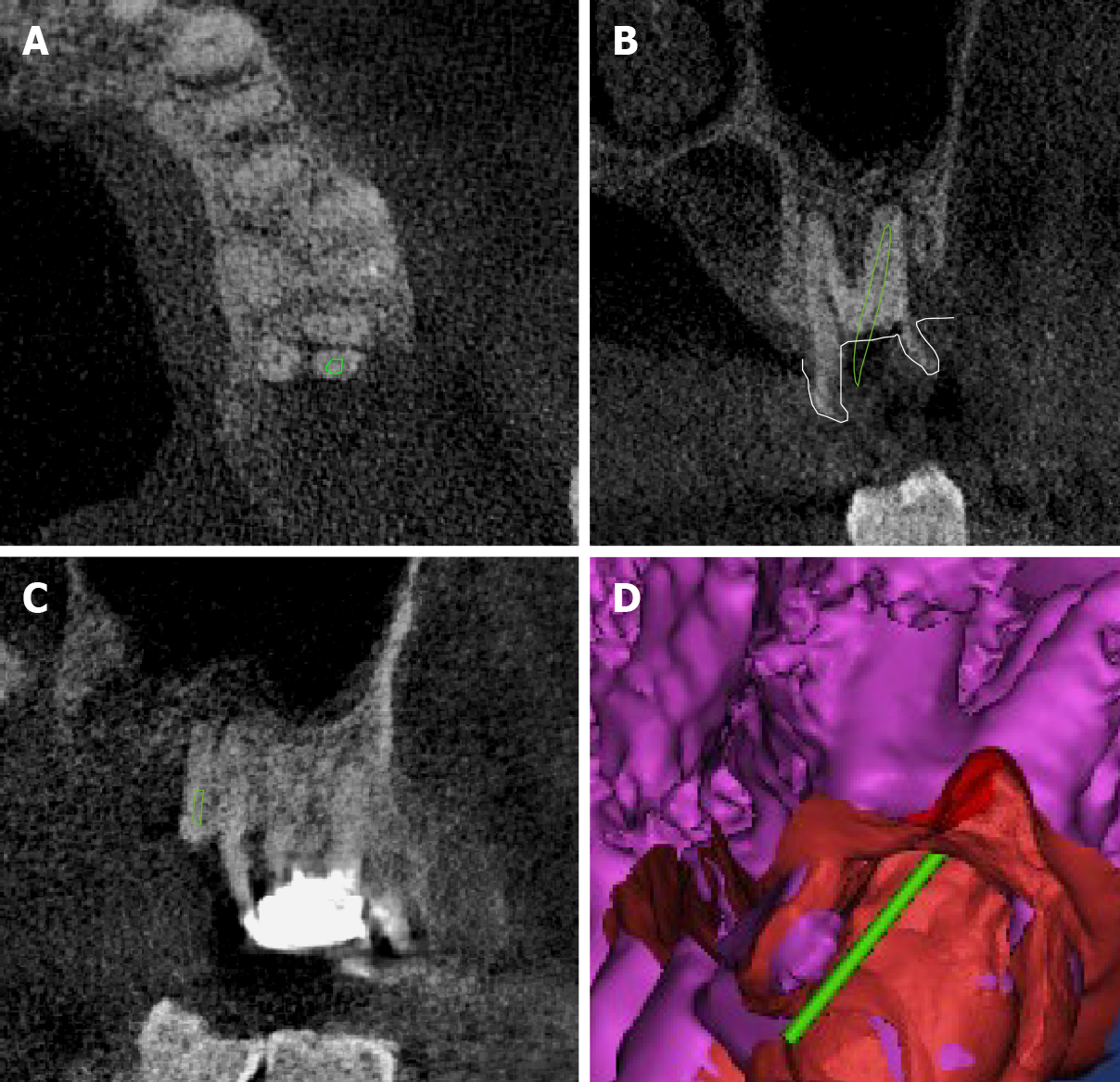
Figure 3 Placement of the virtual root canal file in the ideal location in the three-dimensional space.
Green part refers to the position of the virtual root canal file. A: Axial plane; B: Sagittal plane; C: Mesiodistal plane; D: The position of the virtual root canal file was checked in the “root extraction” digital model.
Figure 4 Printing of the inlay-like guide plate using a three-dimensional printer.
A: The regional growth method and Boolean operation are employed to generate the “inlay-like guide plate” using a 0.6 mm-diameter navigation channel; B: The inlay-like guide plate is three-dimensionally printed with a 0.6 mm-diameter navigation channel, and the E-Guide Tint guide plate material shows good biocompatibility and an esthetically pleasing appearance; C: Wearing the guide plate in a pre-clinical trial.
Figure 5 Root canal preparation guided by the guide plate.
A: The well-fitting guide plate in the correct position (shown by an indication mark); B: The C-pilot file has accurately entered the distal root canal; C: Radiography of the instrument in the root canal.
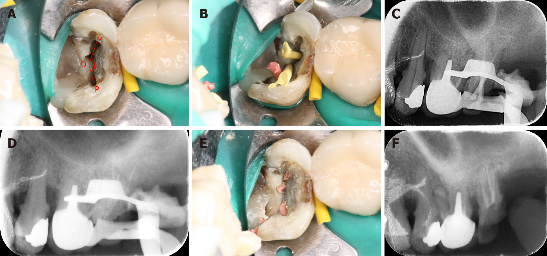
Figure 6 Process of root canal filling.
A: Palatal root canal orifice (P); distal root canal orifice (D); mesial root canal orifice (M); PDM angle = 154.5°, which falls into the “rare” category; B and C: The trial point test; D-F: Root canals are filled with hot gutta-percha.
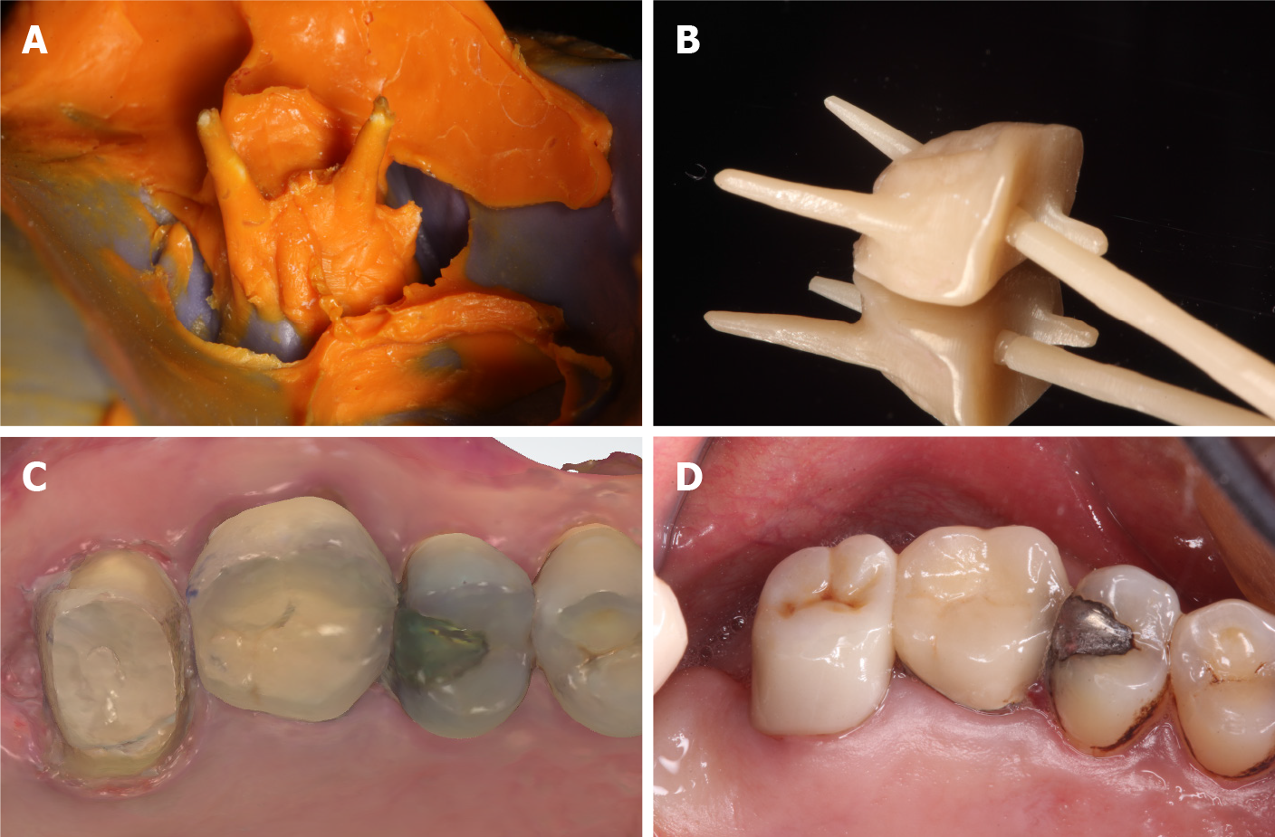
Figure 7 Restoration of the maxillary left second molar.
A: A silicone rubber model of the tooth; B and C: Because of the variation in the root canal and the large angle of bifurcation, the common path of insertion is inconsistent; therefore, “plug-in” post-core restoration is selected; D: The post-core is inserted into the tooth, the abutment tooth is prepared, and the tooth is restored with an all-ceramic crown.
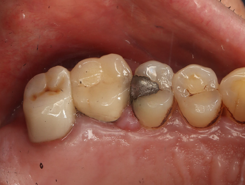
Figure 8 Clinical image at the 2-year follow-up.
Tooth 27 remained asymptomatic 2 years after treatment. The crown shows a satisfactory marginal fit, and there is no gingival edema or erythema.
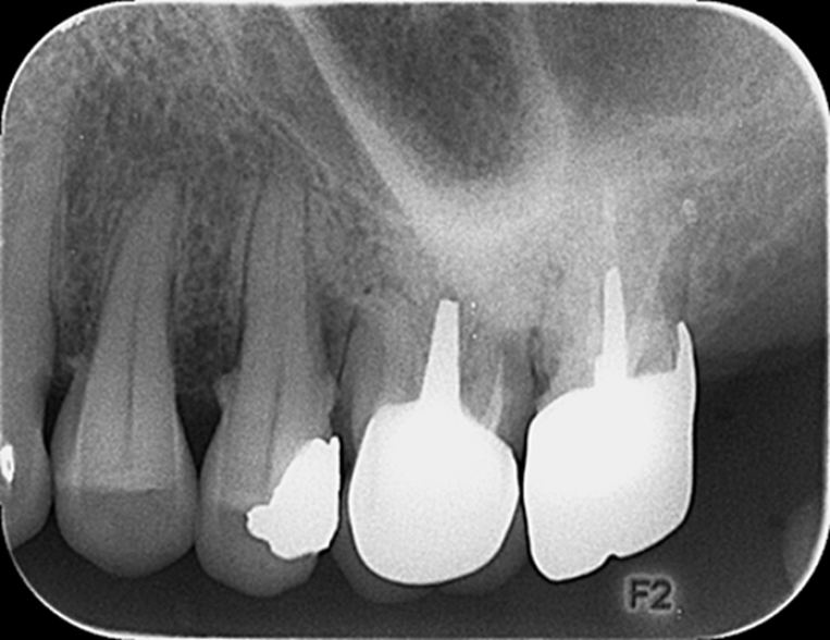
Figure 9 Radiographic image at the 2-year follow-up.
A radiograph obtained 2 years after treatment shows adequately filled canals, with no low-density area in the apical region.
- Citation: Yan YQ, Wang HL, Liu Y, Zheng TJ, Tang YP, Liu R. Three-dimensional inlay-guided endodontics applied in variant root canals: A case report and review of literature. World J Clin Cases 2021; 9(36): 11425-11436
- URL: https://www.wjgnet.com/2307-8960/full/v9/i36/11425.htm
- DOI: https://dx.doi.org/10.12998/wjcc.v9.i36.11425


