Copyright
©The Author(s) 2021.
World J Clin Cases. Oct 6, 2021; 9(28): 8609-8615
Published online Oct 6, 2021. doi: 10.12998/wjcc.v9.i28.8609
Published online Oct 6, 2021. doi: 10.12998/wjcc.v9.i28.8609
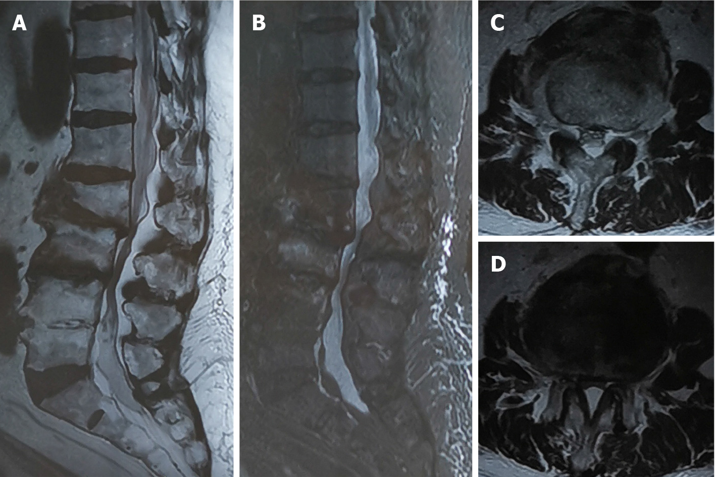
Figure 1 Magnetic resonance imaging showing L3, L4 fracture and L2/3 spinal stenosis.
A and B: Abnormal signs in the vertebral body of L3, L4 and segmental stenosis of L2/3 in sagittal images; C and D: Spinal stenosis of L2/3 in the cross-sectional images.
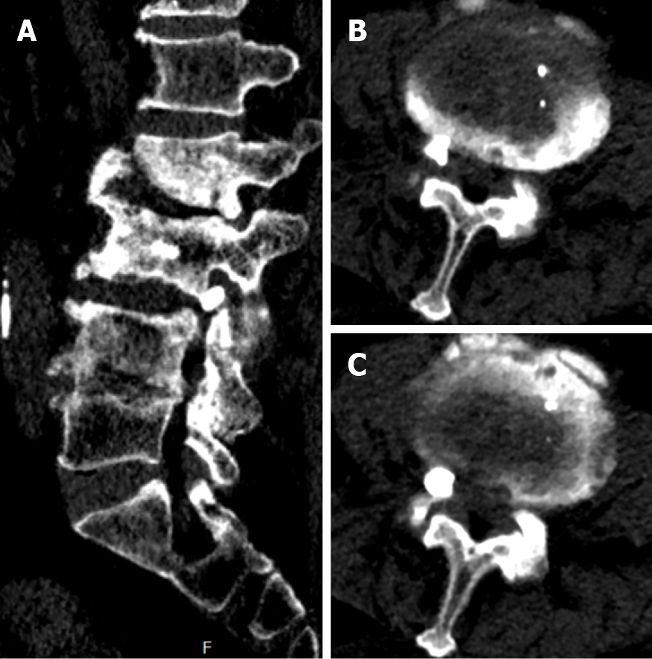
Figure 2 Leakage of bone cement located in the right intervertebral foramen of L3/4.
A: Sagittal image; B and C: Cross-sectional images of L3/4.
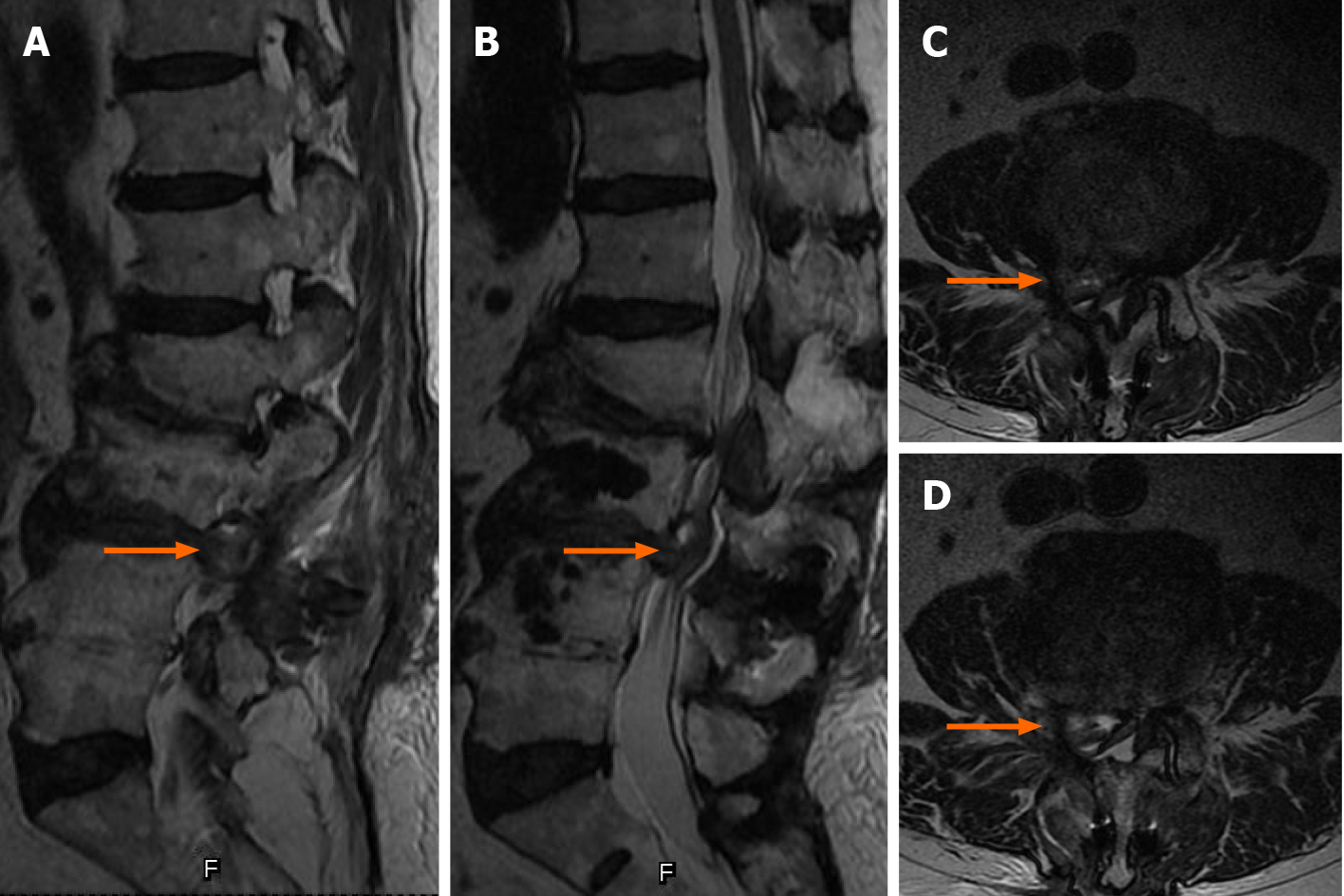
Figure 3 Magnetic resonance imaging showing lumbar disc herniation.
A and B: The herniated disc in the sagittal plane (orange arrow); C and D: The herniated disc in the axial plane (orange arrow).
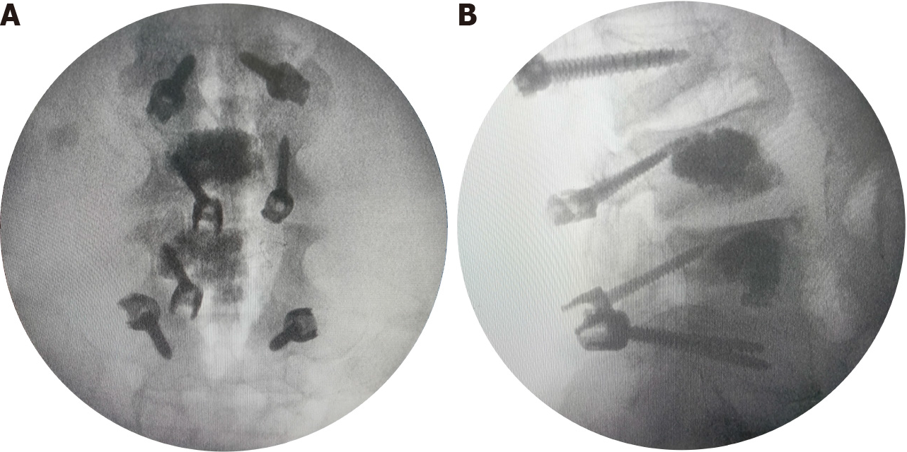
Figure 4 Screw implantation angles and entry points in the intraoperative images.
A: Anteroposterior image; B: Lateral image.
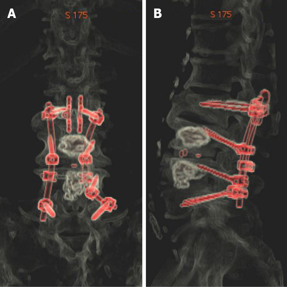
Figure 5 Morphology and location of implants from three-dimensional reconstruction images.
A: Anteroposterior image; B: Lateral image.
- Citation: Chen MM, Jia P, Tang H. Cortical bone trajectory fixation in cemented vertebrae in lumbar degenerative disease: A case report. World J Clin Cases 2021; 9(28): 8609-8615
- URL: https://www.wjgnet.com/2307-8960/full/v9/i28/8609.htm
- DOI: https://dx.doi.org/10.12998/wjcc.v9.i28.8609


