Copyright
©The Author(s) 2020.
World J Clin Cases. Mar 6, 2020; 8(5): 971-979
Published online Mar 6, 2020. doi: 10.12998/wjcc.v8.i5.971
Published online Mar 6, 2020. doi: 10.12998/wjcc.v8.i5.971
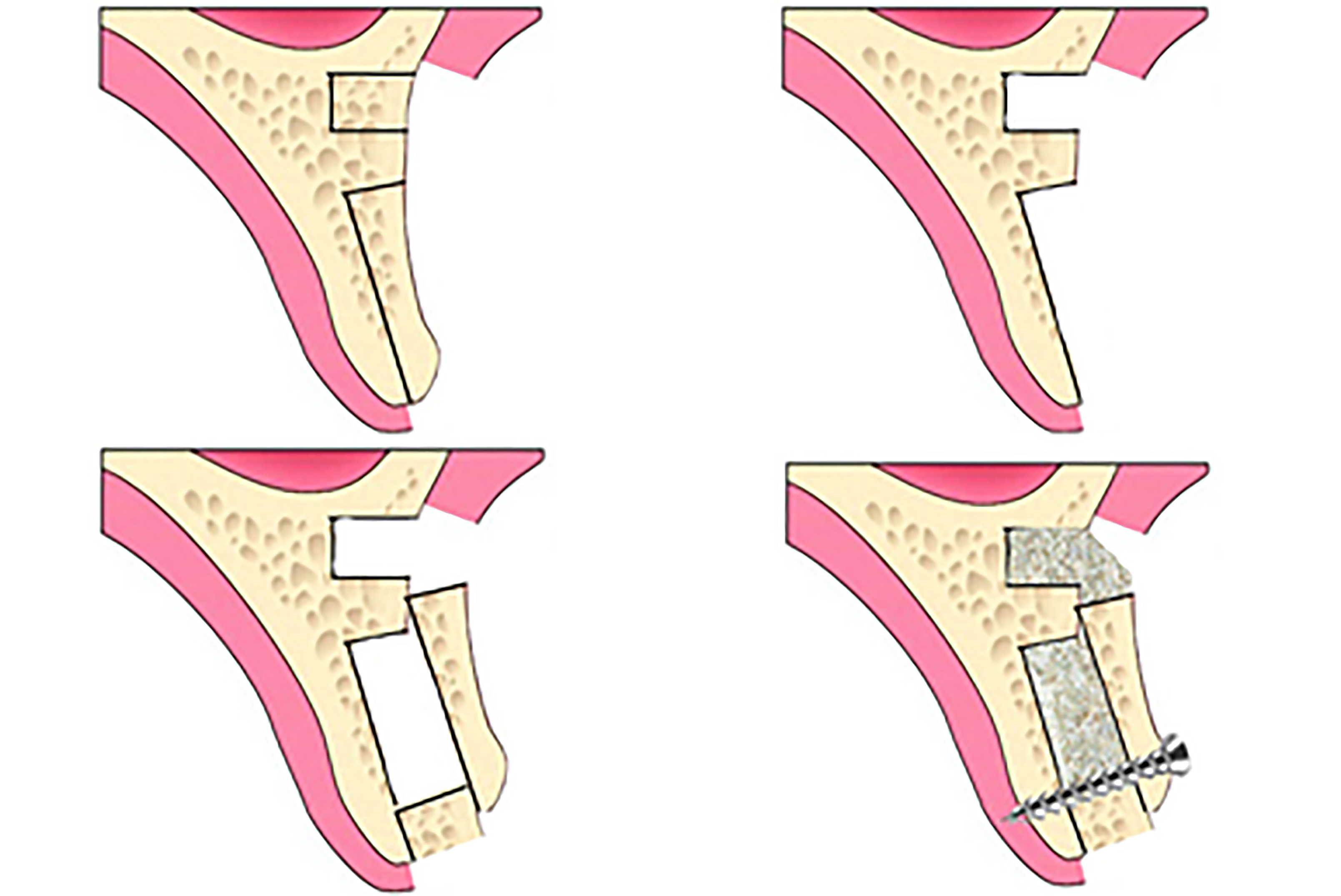
Figure 1 Schematic illustration of the two bone blocks sandwich technique.
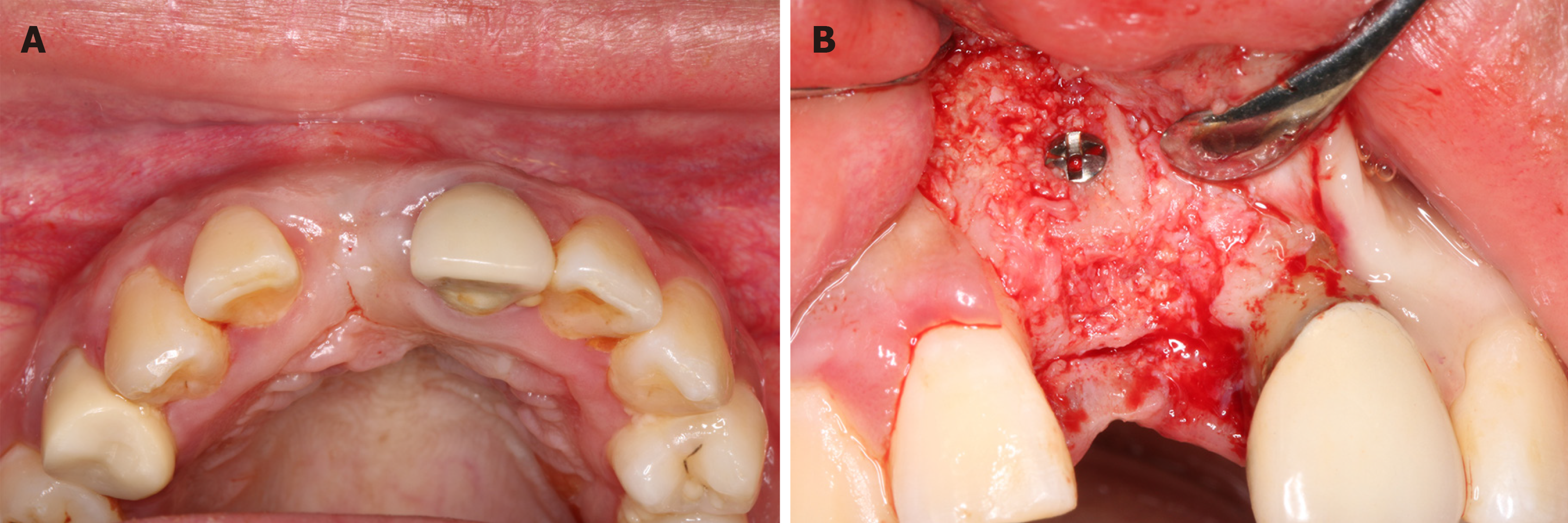
Figure 2 Preoperative intraoral photos.
A: Labial view of the gingival margin level of tooth 11; B: Occlusal view of localized soft tissue collapse of tooth 11.
Figure 3 Preoperative cone beam computer topography cross-sectional view of tooth 11.
Figure 4 The two bone blocks sandwich technique surgical procedure.
A: Preparation of the two bone blocks; B: Placement and fixation of the two bone blocks.
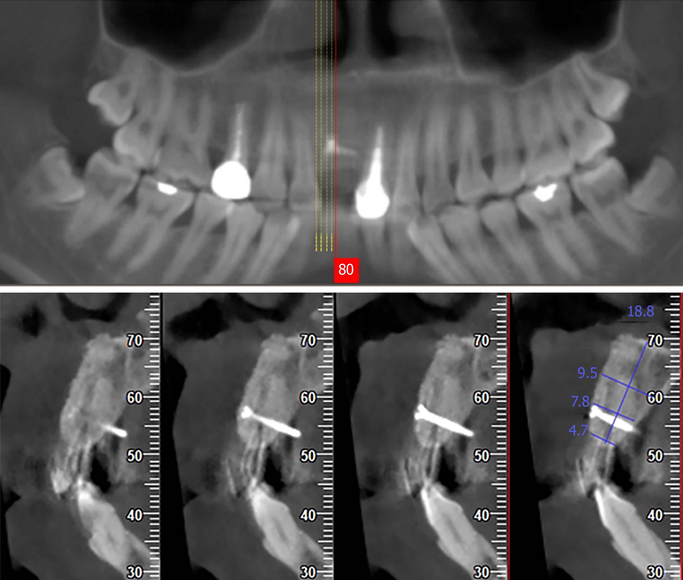
Figure 5 Cone beam computer topography cross-sectional view at 6 mo after the two bone blocks sandwich technique.
Figure 6 Intraoral photos 6 mo after two bone blocks sandwich technique surgery.
A: Occlusal view of the soft tissue contour of tooth 11; B: Lateral view of osteogenesis outcome.
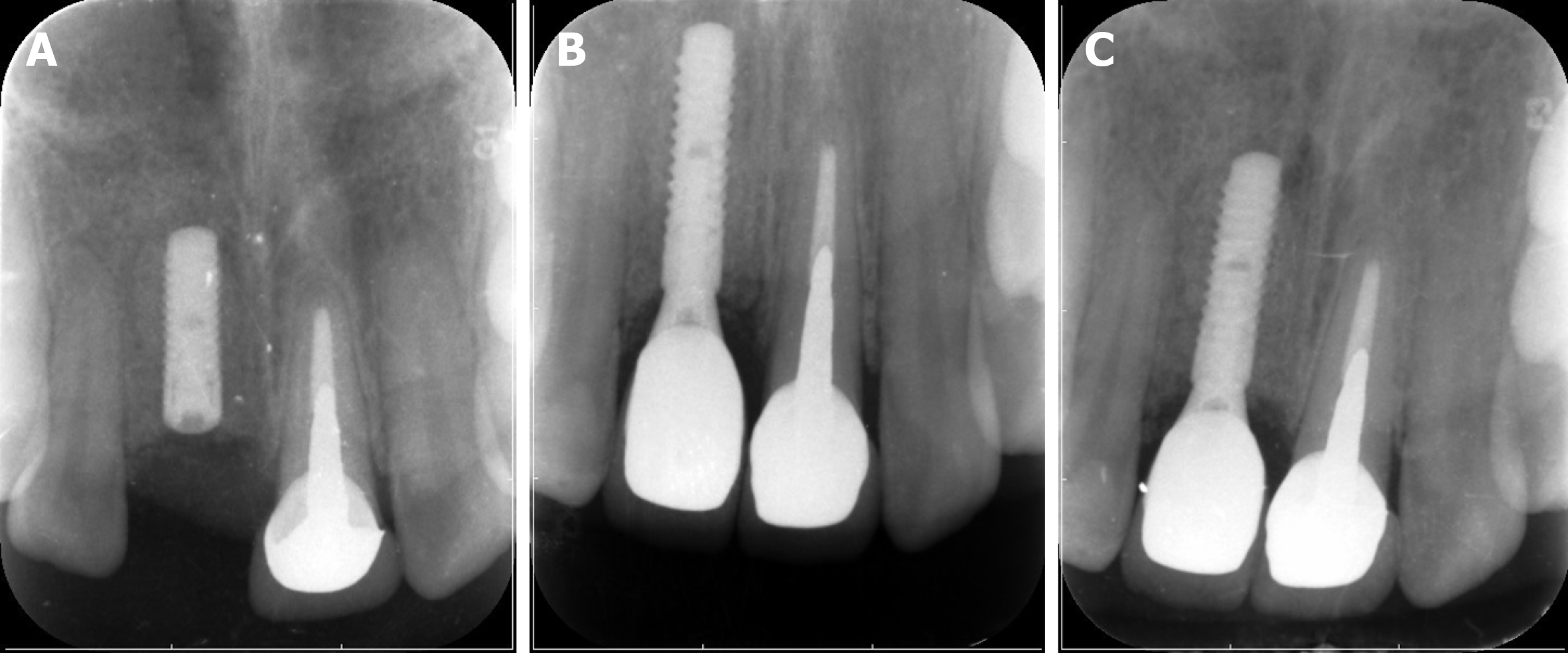
Figure 7 Periapical image at different times.
A: Periapical image after implant placement; B: Periapical image after restoration; C: Periapical image at 1-year follow-up.
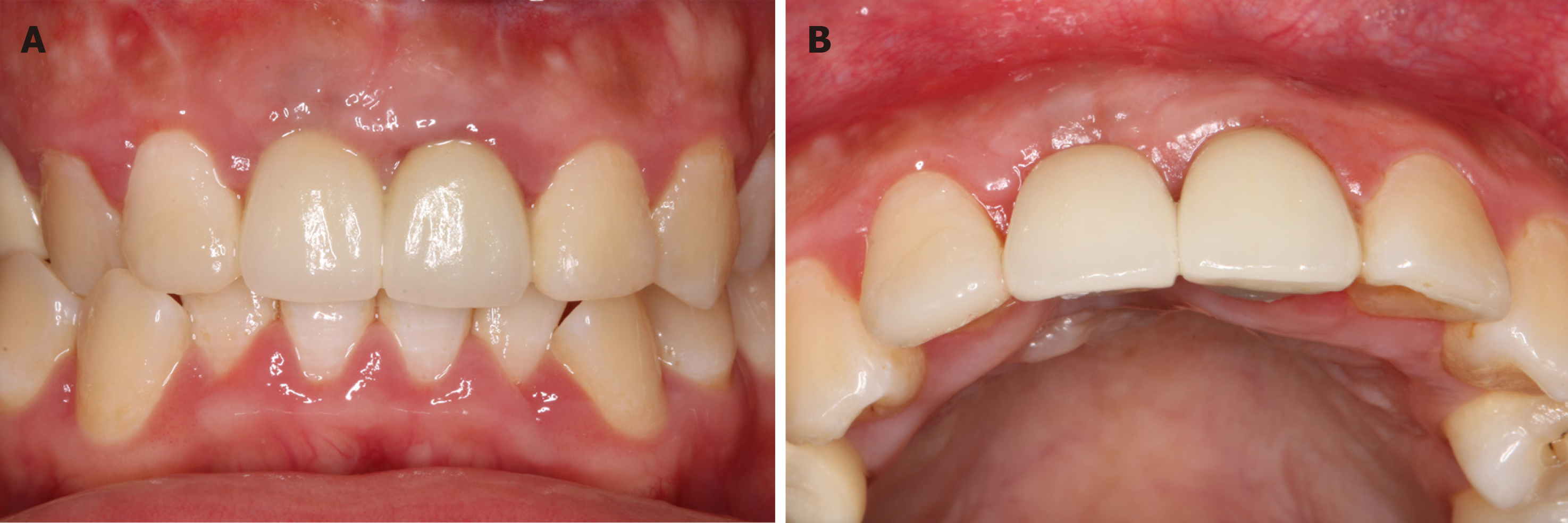
Figure 8 Intraoral photos at 1-year follow-up.
A: Labial view of all-ceramic restorations; B: Occlusal view of soft tissue contour.
- Citation: Xia HB, Zhang YF, Shi B, Wang M. Two bone blocks sandwich technique for horizontal reconstruction of severely atrophic alveolar ridge in anterior maxilla: A case report. World J Clin Cases 2020; 8(5): 971-979
- URL: https://www.wjgnet.com/2307-8960/full/v8/i5/971.htm
- DOI: https://dx.doi.org/10.12998/wjcc.v8.i5.971


