Copyright
©The Author(s) 2020.
World J Clin Cases. Sep 6, 2020; 8(17): 3890-3902
Published online Sep 6, 2020. doi: 10.12998/wjcc.v8.i17.3890
Published online Sep 6, 2020. doi: 10.12998/wjcc.v8.i17.3890
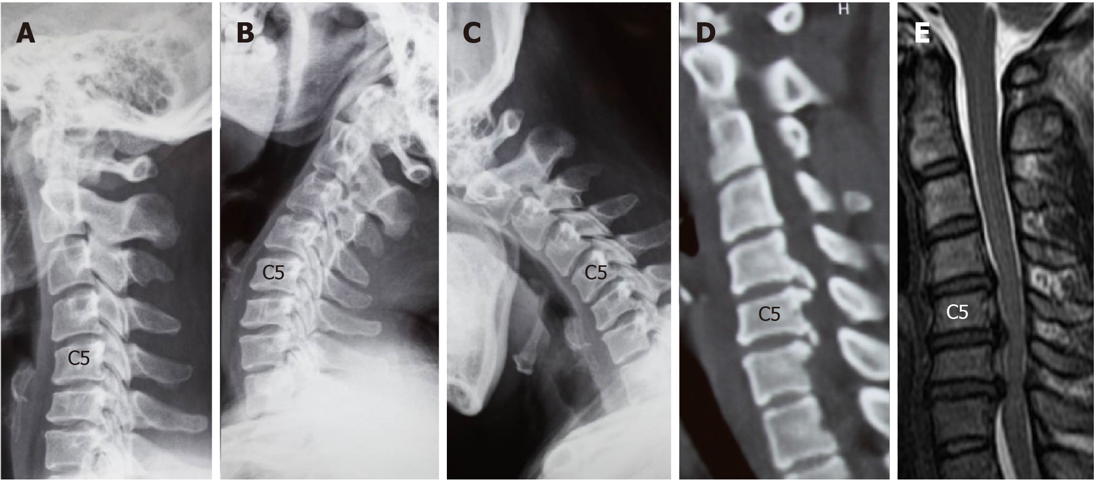
Figure 1 Computed tomography images of case 1.
A-C: Lateral radiographs showing a straightened cervical alignment that returned during flexion-extension movement. The range of motion at C4/5, C5/6, and C6/7 was 11.3°, 14.53°, and 1.28°, respectively; D: Computed tomography image showing large numbers of osteophytes at the posterior border of C5/6 and C6/7; E: Magnetic resonance imaging revealed cervical disc herniation at C4/5 and C6/7.
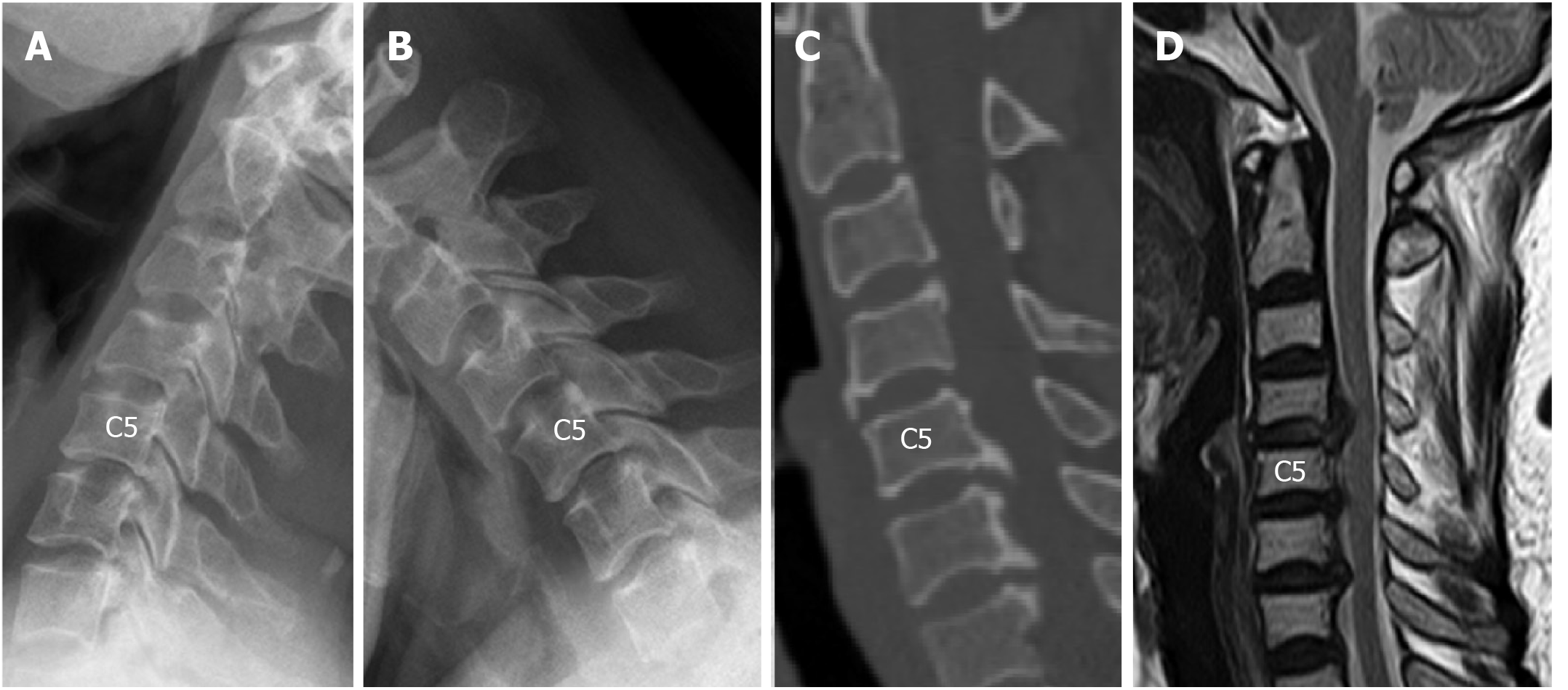
Figure 2 Computed tomography images of case 2.
A and B: Lateral radiographs taken before surgery revealed that the range of motion at C5/6 was decreased (2.57°), while the range of motion at C4/5 and C6/7 was 9.34° and 6.05°, respectively. The intervertebral disc height at C4/5 was preserved; C: Large numbers of osteophytes were revealed at the posterior-inferior border of C5 and C6; D: Magnetic resonance imaging indicated spinal cord compression at C4/5, C5/6, and C6/7, and compression at C4/5 was caused by disc herniation.
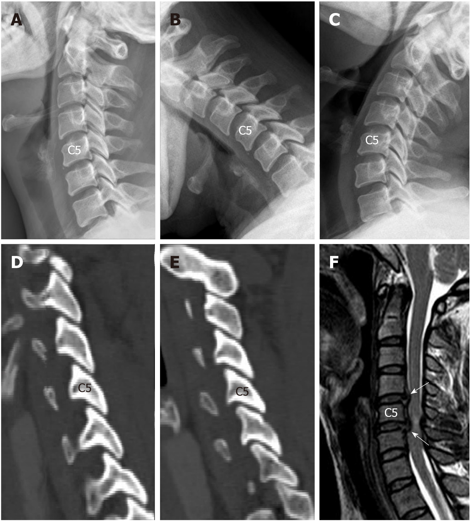
Figure 3 Spinal compression was mainly caused by disc herniation, and the facet joints were normal.
A-C: Range of motion at C5/6 and C6/7 was 11.93° and 11.28°, respectively, and the intervertebral disc height at both levels was slightly decreased; D and E: There was no obvious degeneration of the facet joints; F: Magnetic resonance imaging revealed soft disc herniation at C5/6 and C6/7.
Figure 4 Computed tomography images of case 4.
A-C: Range of motion at C4/5 and C5/6 was 10.63° and 9.93°, respectively, and the intervertebral disc height at both levels was slightly decreased; D and E: There was no obvious degeneration of the facet joints; F: Magnetic resonance imaging revealed soft disc herniation at C4/5 and C5/6.
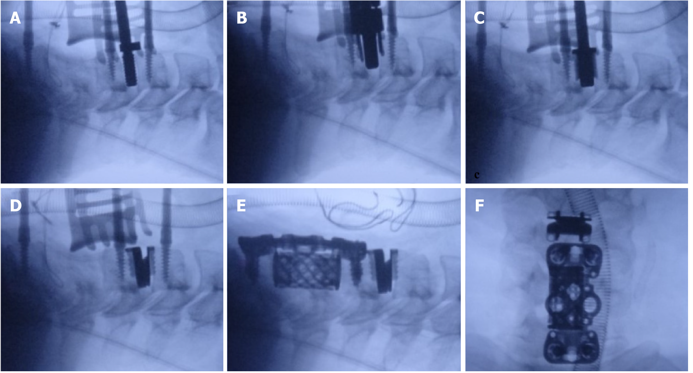
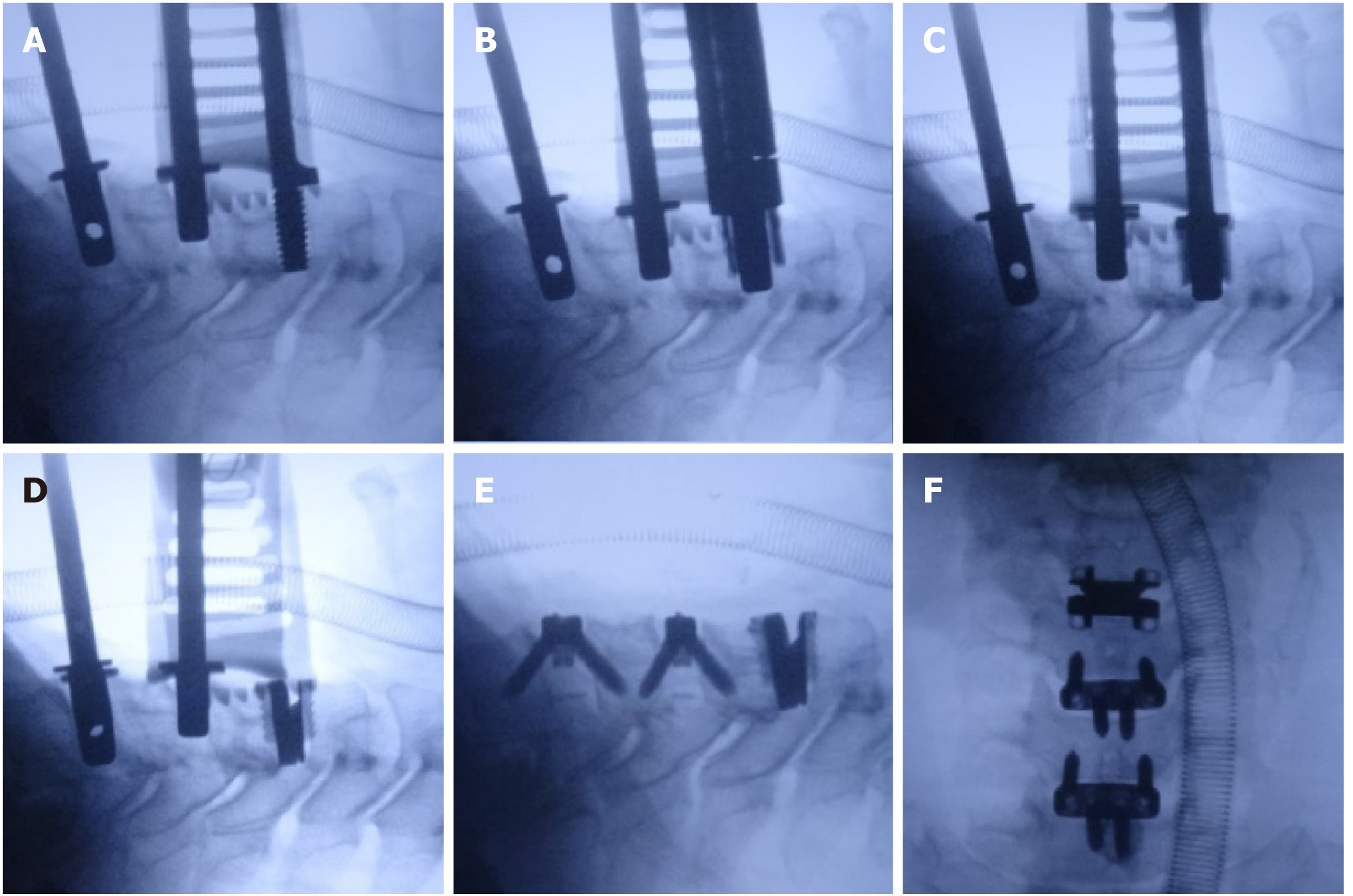
Figure 5 The surgical procedure used for the hybrid surgery combining cervical disc replacement with anterior cervical corpectomy decompression and fusion in case 1.
A: The decompression at C5/6 and C6/7 was performed first, and then the decompression and endplate preparation were finished at C4/5. The C4/5 disc space was inserted with an appropriate sized implant trial; B and C: The drilling and cutting processes were performed following the standard procedure; D: An appropriately sized artificial disc was inserted at C4/5; E: Anterior cervical corpectomy decompression and fusion was completed at C5-7 level; F: Lateral radiograph was taken to confirm the implants in good position.
Figure 6 The surgical procedure of the hybrid surgery combining cervical disc replacement with ACDF in case 2.
A: Decompression and endplate preparation were performed at C4/5, C5/6, and C6/7. Cervical disc replacement was performed before anterior cervical discectomy and fusion; B-D: Drilling, cutting, and implanting processes of cervical disc replacement were performed. The C5/6 and C6/7 disc spaces were supported by implant trails; E: Anterior cervical discectomy and fusion was performed at C5/6 and C6/7; F: Lateral radiograph was taken to confirm the implants in good position.
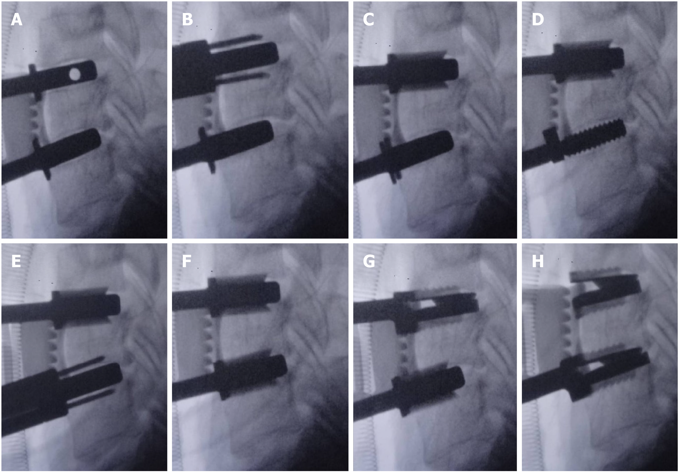
Figure 7 The surgical procedure of continuous two-level cervical disc replacement in case 3.
A: The disc space was maintained with appropriately sized implant trails; B and C: Rasping, drilling, and cutting were performed at C5/6, and the implant trail at C6/7 was reserved; D-F: Rasping, drilling, and cutting were performed at C6/7, and the implant trail at C5/6 was reserved; G and H: Artificial discs were implanted at C5/6 and C6/7 following a top-down sequence.
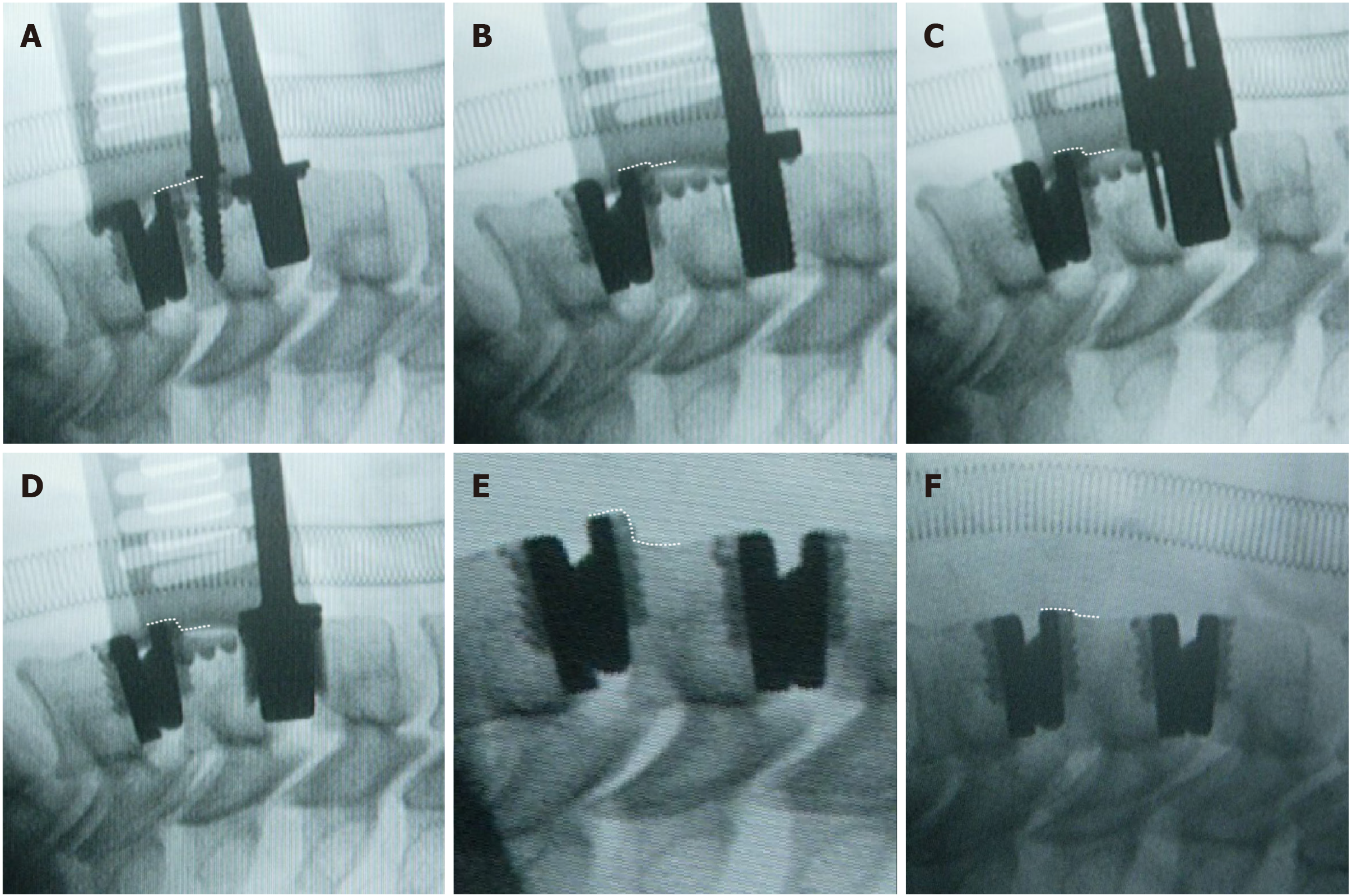
Figure 8 The surgical procedure of continuous two-level cervical disc replacement, which followed a bottom-up sequence in case 4.
A-E: The upper tab of the prosthesis at C5/6 migrated forward during preparation of the disc space at C4/5. The degree of anterior migration of the artificial disc at C5/6 is denoted with dashed lines; F: We tapped the migrated tab back to the correct position.
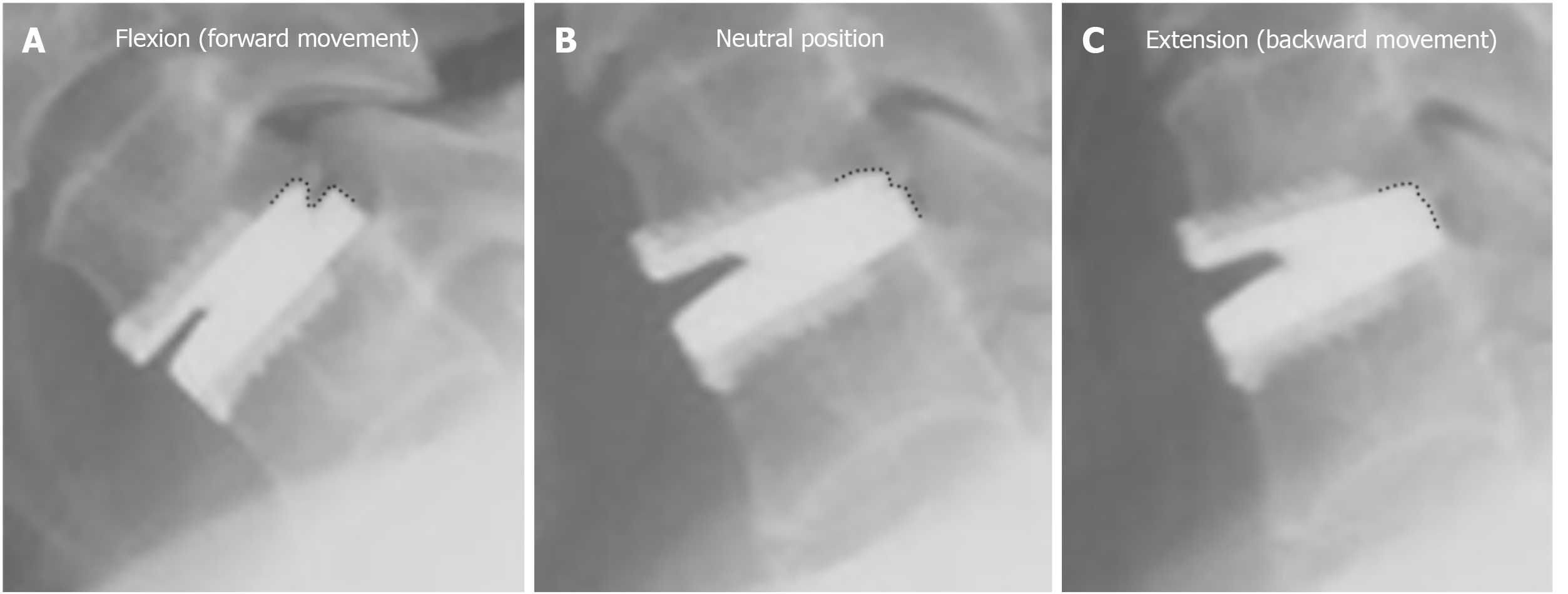
Figure 9 The position of the upper tab relative to the lower tab (denoted with dashed lines) of Prestige-LP in flexion (A), neutral position (B), and extension (C).
The Prestige-LP cervical disc was designed with a ball and socket structure, with the ball to the rear of the upper tab and the socket on the lower tab. This design allowed the prosthesis to move transversely; the forward displacement was larger, and the prosthesis could move only slightly backward.
Figure 10 The mechanism underlying the condition occurring in case 4.
A: The impact force generated by tapping processes allowed the C5 vertebra as well as the upper tab at C5/6 to move backward; B: While the posterior border of the ball continued to contact the posterior border of the socket at C5/6, the backward movement of the upper tab at C5/6 was restricted due to the design of the prosthesis. Therefore, a shearing force was generated between the C5 vertebral body and the upper tab at C5/6. Affected by this shearing force, the upper tab at C5/6 finally migrated forward; C and D: If we inserted the prosthesis using a top-down sequence, the anterior border of the socket on the lower tab at C4/5 would barely contact the ball on the upper tab at C4/5. Therefore, no shearing force would be generated between the lower tab at C4/5 and the C5 vertebral body, and the prosthesis would not migrate.
- Citation: Wang XF, Meng Y, Liu H, Hong Y, Wang BY. Surgical strategy used in multilevel cervical disc replacement and cervical hybrid surgery: Four case reports. World J Clin Cases 2020; 8(17): 3890-3902
- URL: https://www.wjgnet.com/2307-8960/full/v8/i17/3890.htm
- DOI: https://dx.doi.org/10.12998/wjcc.v8.i17.3890


