Copyright
©The Author(s) 2024.
World J Clin Cases. Jul 16, 2024; 12(20): 4108-4120
Published online Jul 16, 2024. doi: 10.12998/wjcc.v12.i20.4108
Published online Jul 16, 2024. doi: 10.12998/wjcc.v12.i20.4108
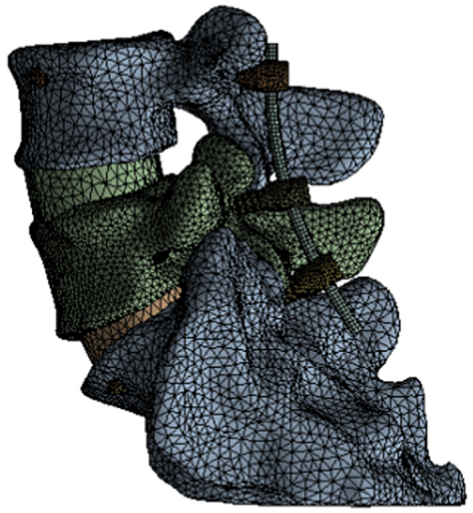
Figure 1 Finite element models of vertebral bodies and pedicle screws.
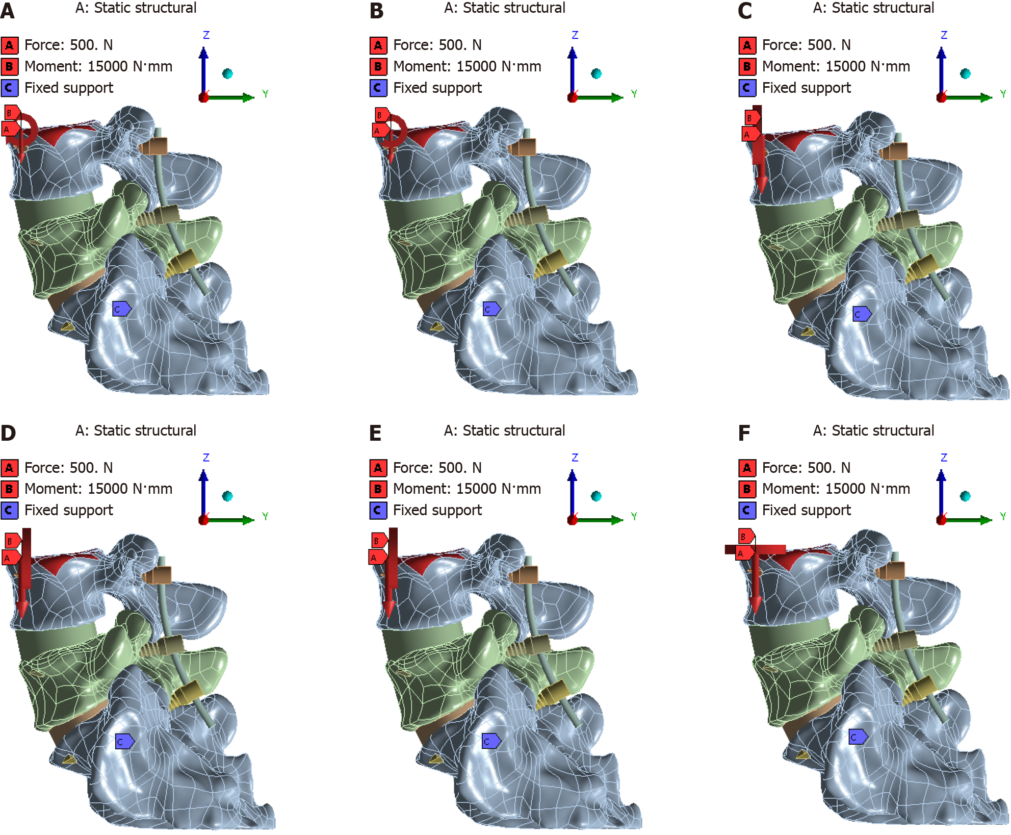
Figure 2 Diagram depicting application of loads during human forward bending, backward extension, rotation, and lateral bending.
A: Extension; B: Forward bending; C: Right lateral bending; D: Left lateral bending; E: Right rotation; F: Left rotation.
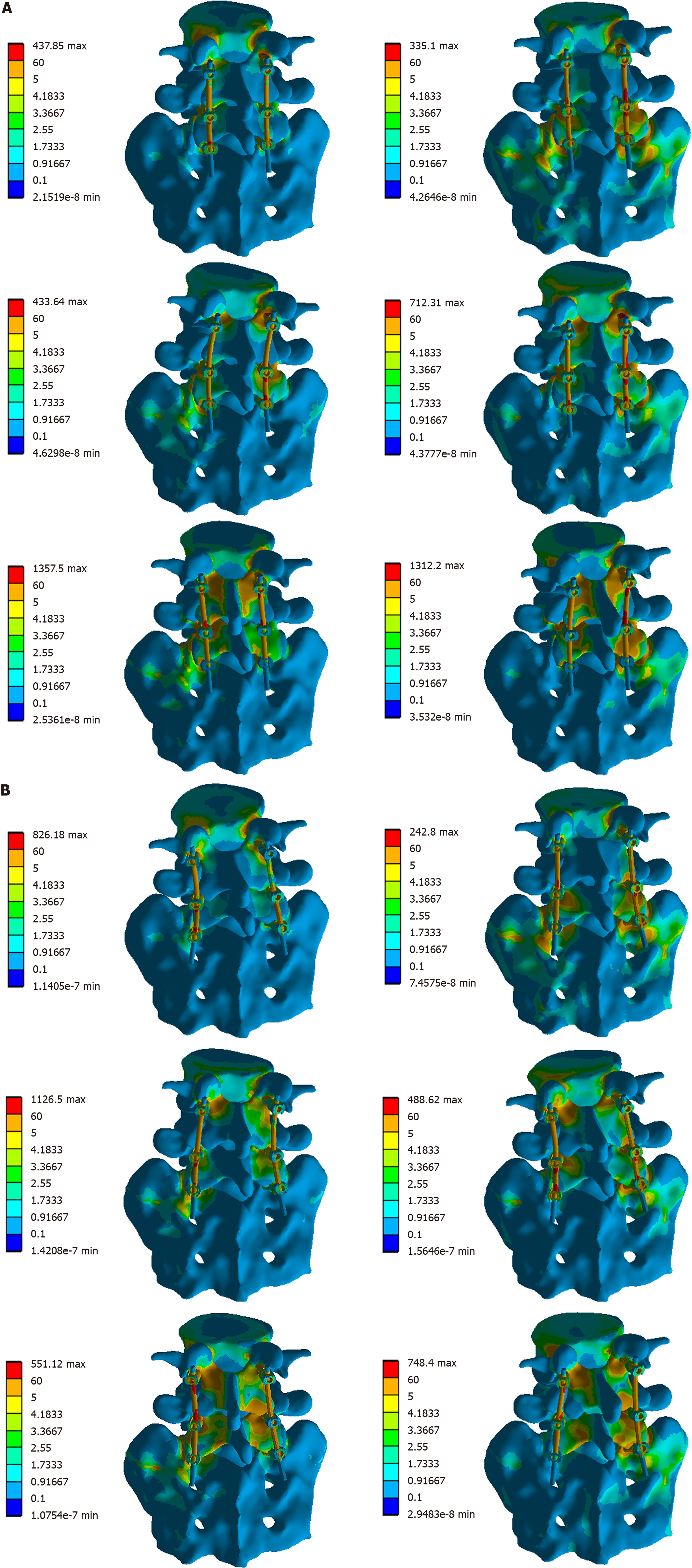
Figure 3 Vertebral stress distribution map.
A: Vertebral stress distribution at 0-degree transverse section angle (TSA); B: Vertebral stress distribution at 17-degree TSA.
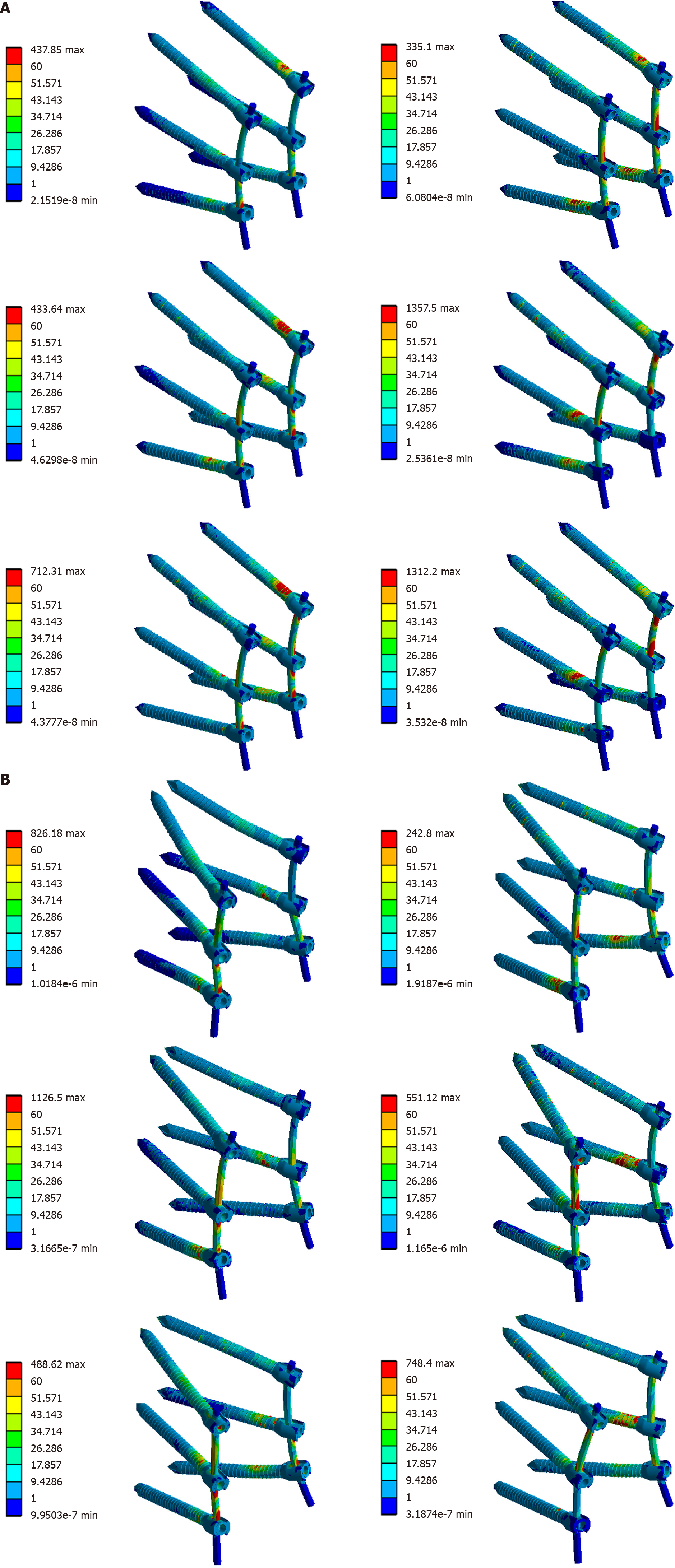
Figure 4 Rod system stress distribution.
A: Stress distribution of the pedicle screw system at 0-degree transverse section angle (TSA); B: Stress distribution at 17-degree TSA.
- Citation: Jiang JH, Zhao CM, Zhang J, Xu RM, Chen L. Biomechanical effects of posterior lumbar interbody fusion with vertical placement of pedicle screws compared to traditional placement. World J Clin Cases 2024; 12(20): 4108-4120
- URL: https://www.wjgnet.com/2307-8960/full/v12/i20/4108.htm
- DOI: https://dx.doi.org/10.12998/wjcc.v12.i20.4108


