Copyright
©The Author(s) 2024.
World J Clin Cases. Jan 16, 2024; 12(2): 431-442
Published online Jan 16, 2024. doi: 10.12998/wjcc.v12.i2.431
Published online Jan 16, 2024. doi: 10.12998/wjcc.v12.i2.431
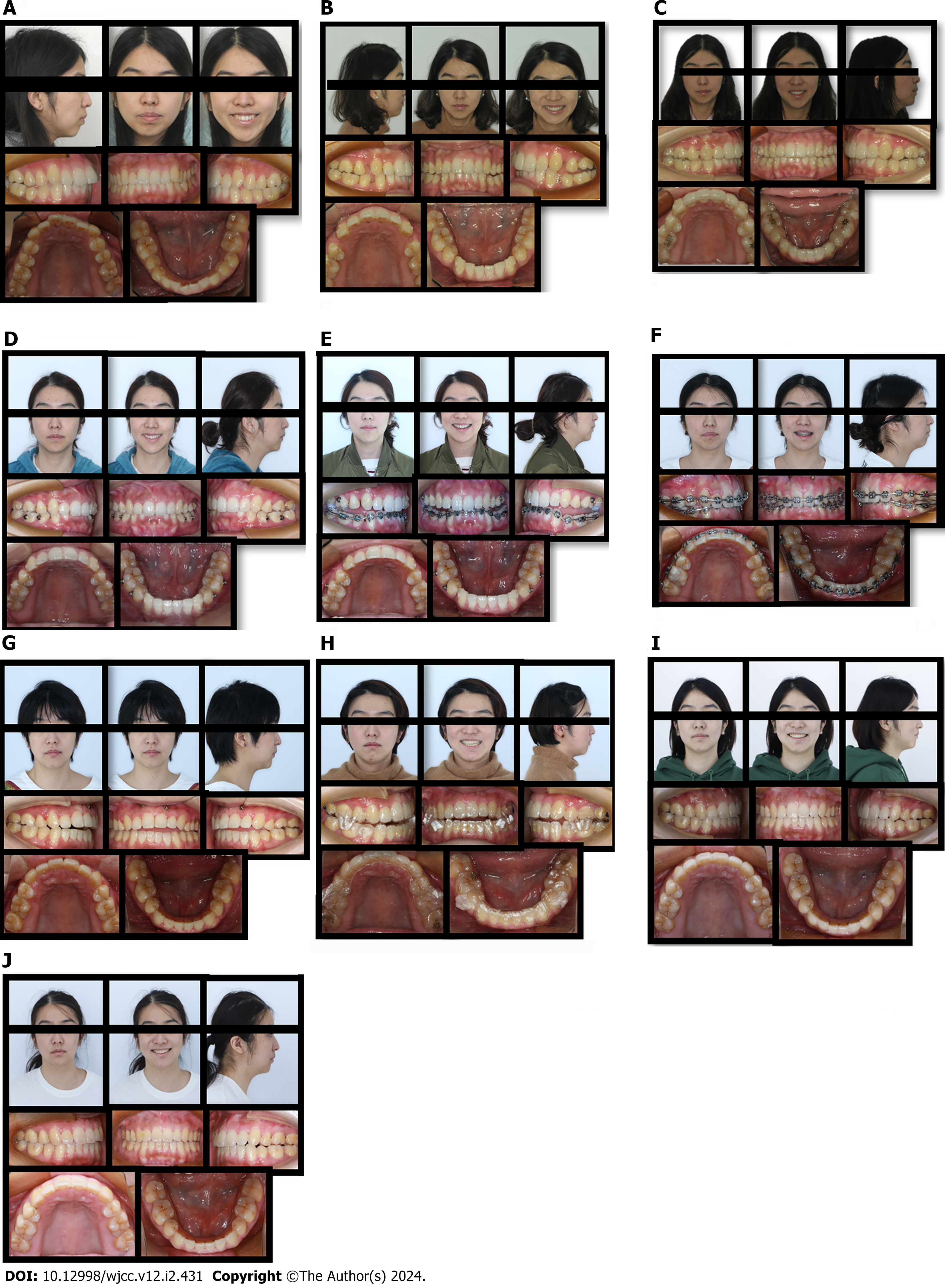
Figure 1 Pretreatment facial, intraoral and progress photographs.
A: Pretreatment facial and intraoral photographs; B: Progress photographs in the 8th month; C: Progress photographs in the 11th month of the treatment (after 3 mo rest); D: Progress photographs in the 18th month; E: Progress photographs in the 19th month; F: Progress photographs in the 26th month; G: Photographs after fixed treatment; H: Wearing mandibular advancement to forward the mandibular positioning in the 44th month of treatment; I: Final photographs; J: Photographs after 1 years of follow-up.
Figure 2 Dental models.
A: Pretreatment dental models; B: Dental models after fixed treatment; C: Final intraoral dental models.
Figure 3 Pretreatment lateral cephalometric and panoramic radiographs.
A: Initial cephalometric radiograph; B: Cephalometric tracing; C-E: Panoramic radiograph.
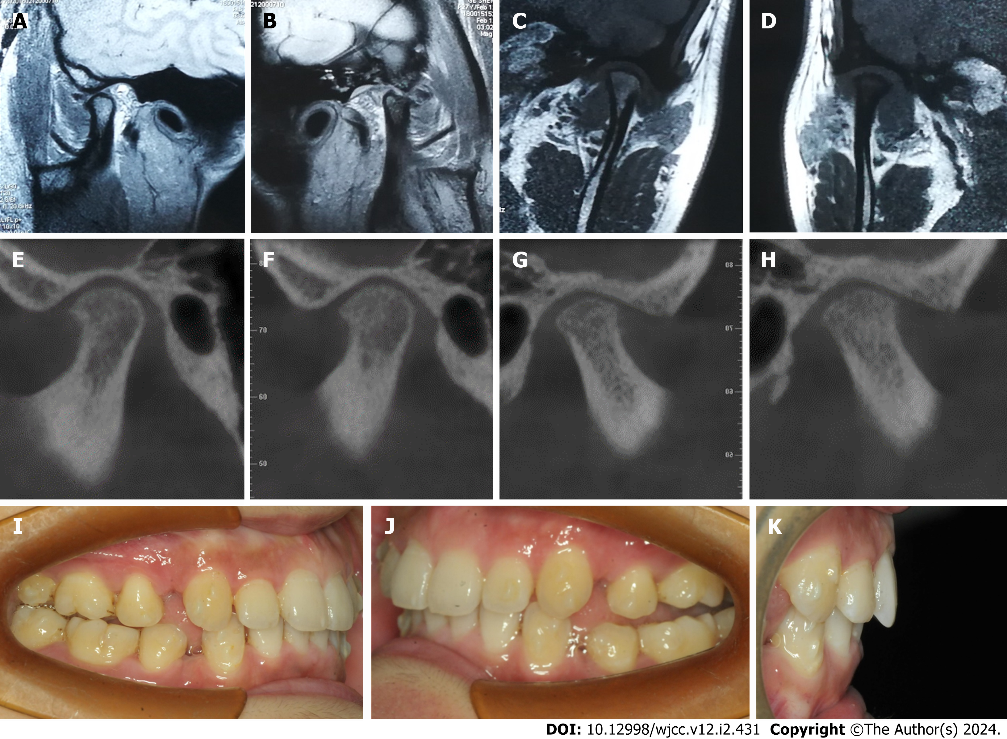
Figure 4 Magnetic resonance imaging images, cone-beam computed tomography images and intraoral photos: 8th month of the treatment.
A and B: Magnetic resonance imaging (MRI) images of right and left temporomandibular joints (TMJ) in opening position; C and D: MRI images of right and left TMJ in closed position; E-H: Cone-beam computed tomography images of right and left TMJ in closed position; I-K: Intraoral photos.
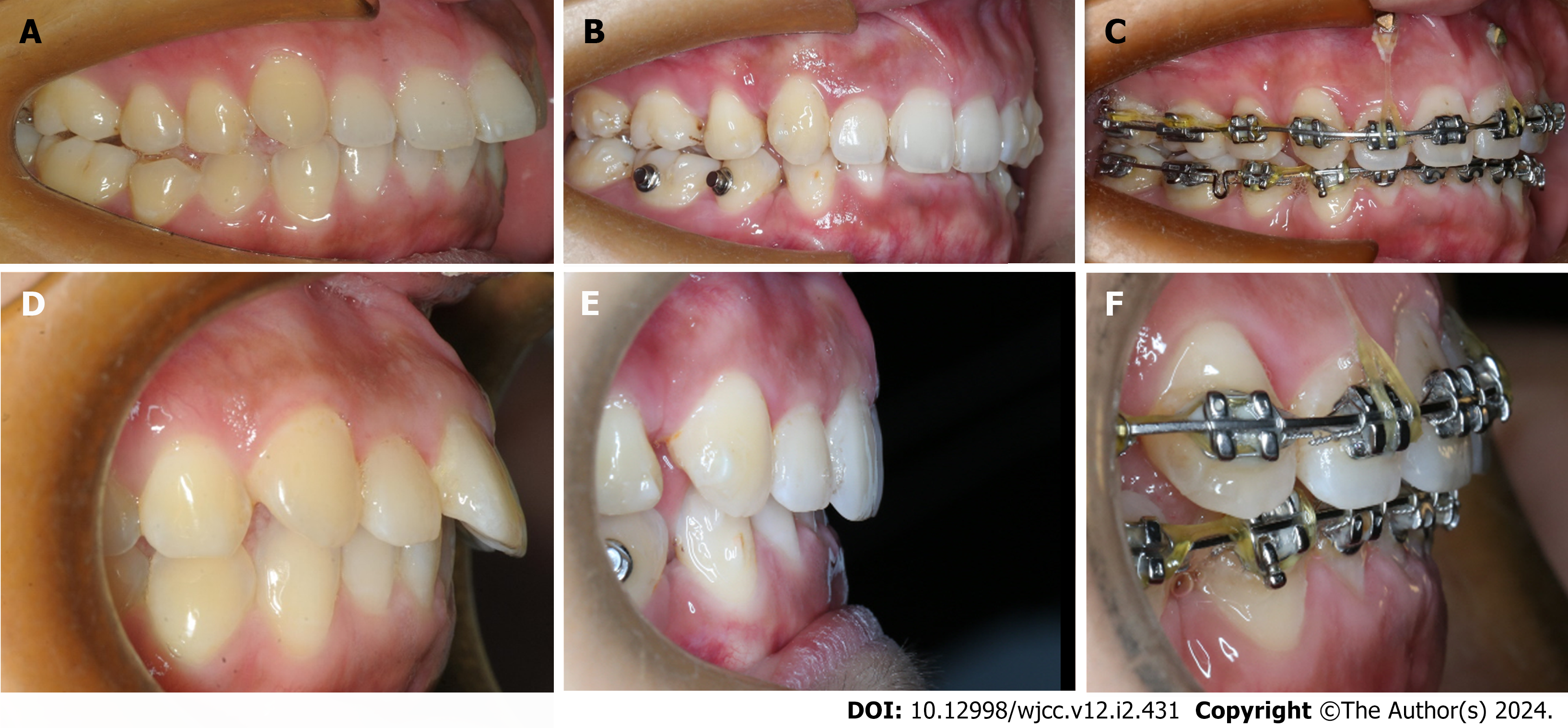
Figure 5 Intraoral overbite photographs.
A and D: First visit; B and E: 19th month; C and F: 29th month.
Figure 6 Dual bite at the 31st month of treatment.
A-C: Intraoral photos in centric relation (CR) position; D-F: Intraoral photos in maximum intercuspation (MI) position; G-H: 3D images of temporomandibular joints (TMJ) in CR and MI positions; I-L: Computed tomography images of TMJ in CR and MI positions.
Figure 7 Cephalometric tracing and cephalometric measurements.
A: First visit; B: In centric relation position; C: In maximum intercuspation position.
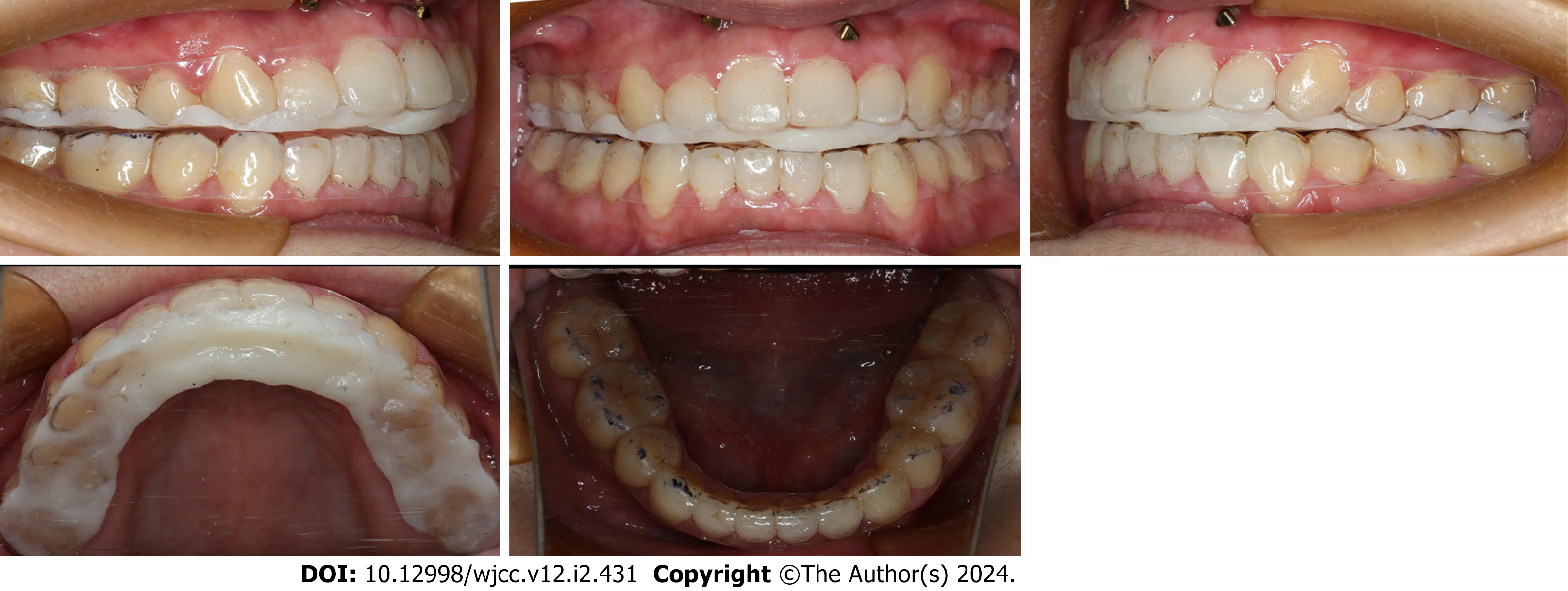
Figure 8 Wearing stable occlusal splint to improve open-bite: 43rd month of treatment.
Intraoral photographs.
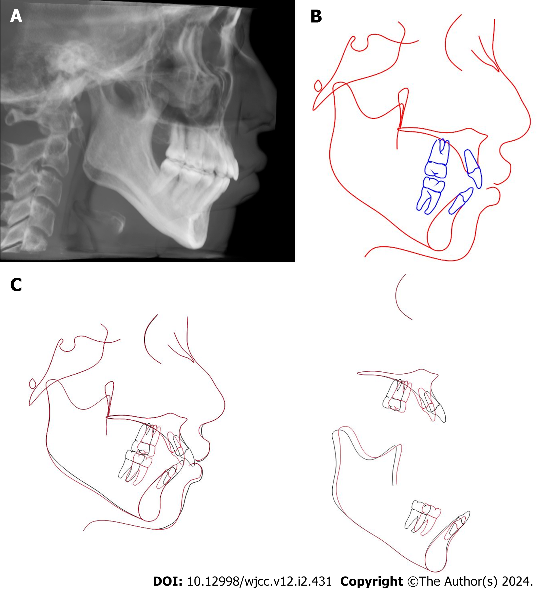
Figure 9 Cephalometric radiograph and superimpositions.
A: Final cephalometric radiograph; B: Cephalometric tracing; C: Superimposition of lateral cephalograms (pretreatment: black, post treatment: red)
Figure 10
Orthodontic treatment flowchart.
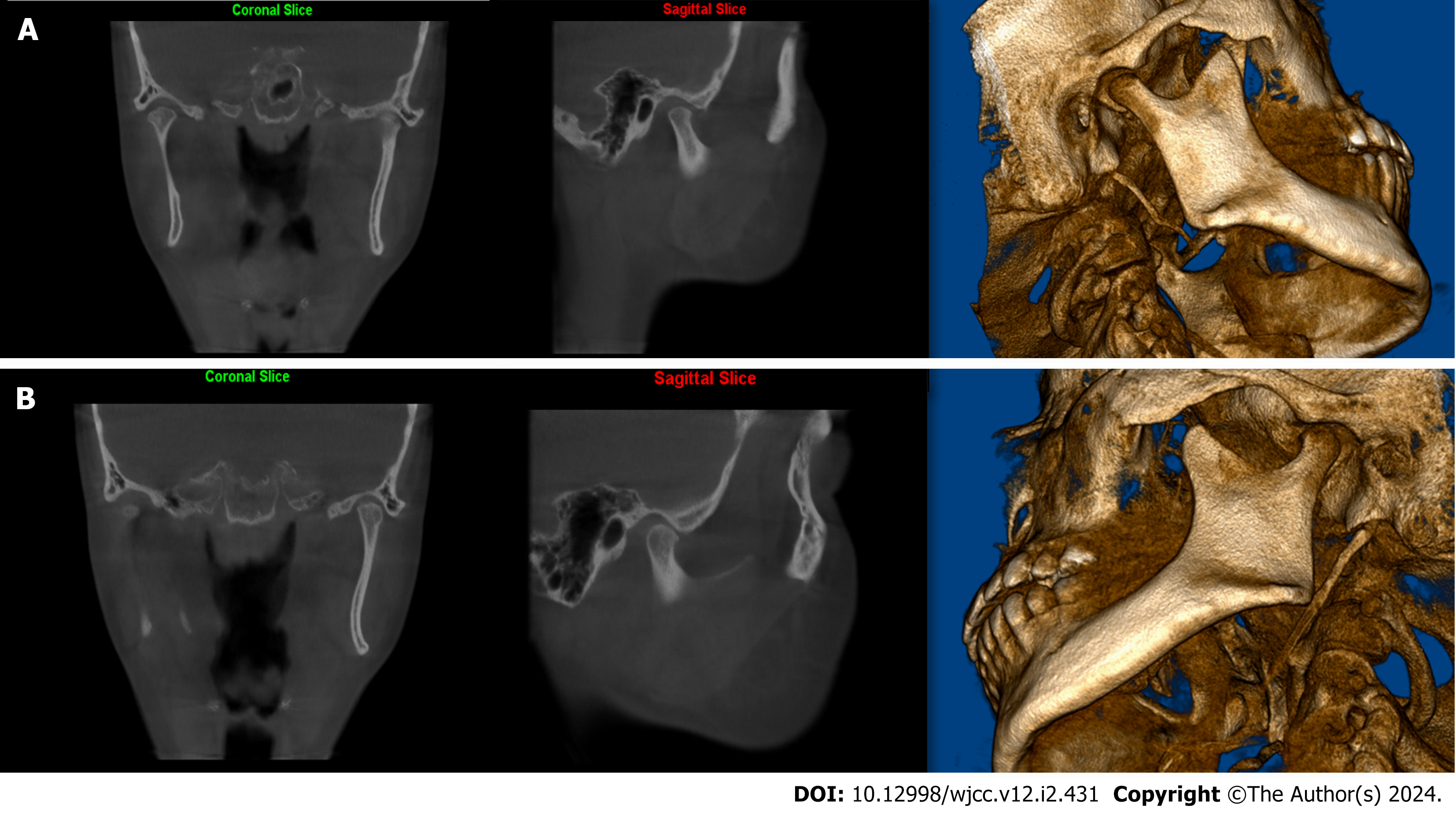
Figure 11 Computed tomography images of temporomandibular joints after 1 years of follow-up.
A: Right temporomandibular joint (TMJ) images; B: Left TMJ images.
- Citation: Lu T, Mei L, Li BC, Huang ZW, Li H. Hybrid treatment of varied orthodontic appliances for a patient with skeletal class II and temporomandibular joint disorders: A case report and review of literature. World J Clin Cases 2024; 12(2): 431-442
- URL: https://www.wjgnet.com/2307-8960/full/v12/i2/431.htm
- DOI: https://dx.doi.org/10.12998/wjcc.v12.i2.431


