Copyright
©The Author(s) 2023.
World J Clin Cases. Aug 26, 2023; 11(24): 5762-5771
Published online Aug 26, 2023. doi: 10.12998/wjcc.v11.i24.5762
Published online Aug 26, 2023. doi: 10.12998/wjcc.v11.i24.5762
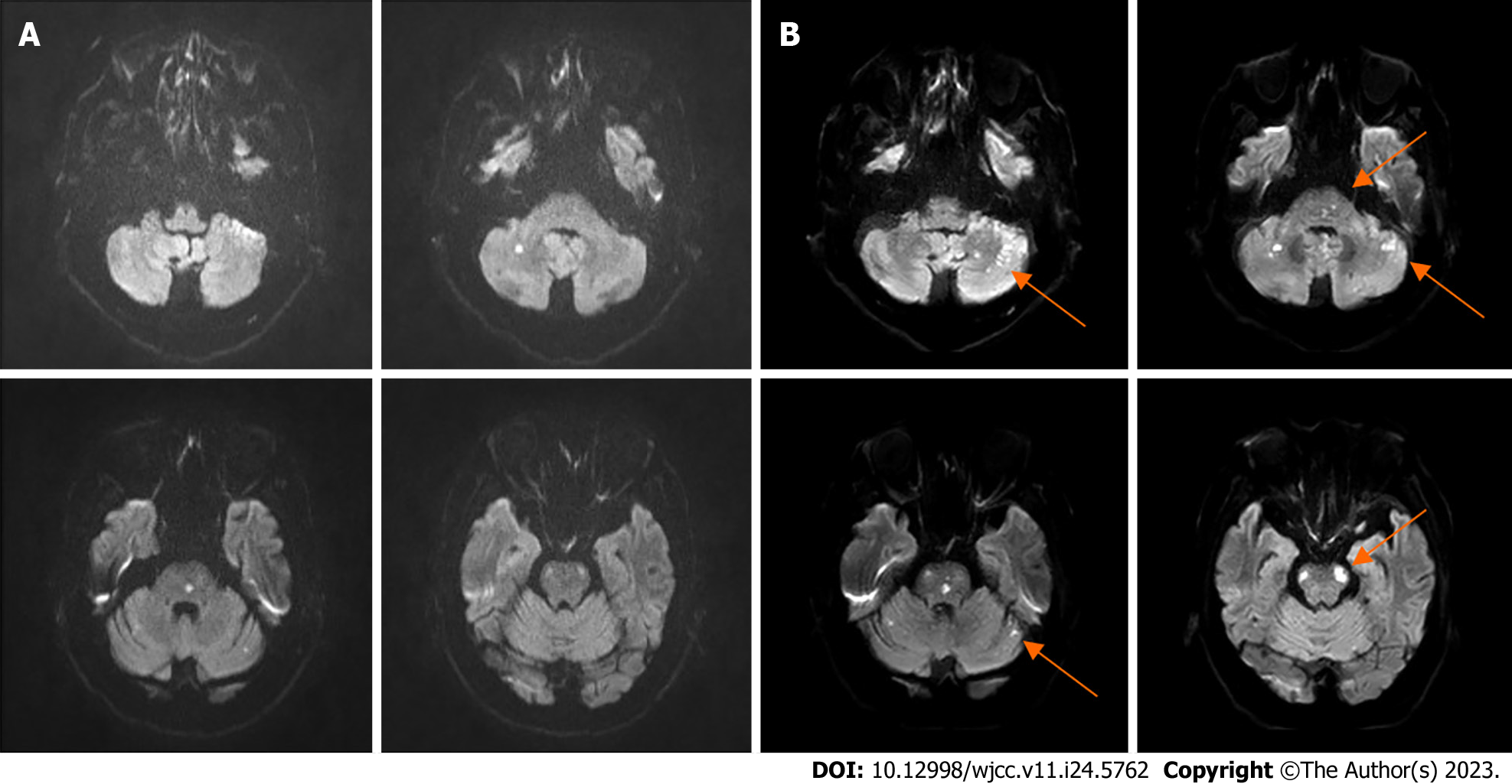
Figure 1 The brain diffusion-weighted magnetic resonance imaging at different time intervals.
A: Diffusion-weighted magnetic resonance imaging (DW-MRI) at initial admission; B: DW-MRI on day 4 of admission showed multiple infarcts enlarged than before (orange arrows).
Figure 2 Digital subtraction angiography of bilateral vertebral arteries.
A: The left intracranial vertebral artery (VA) has been occluded with a blunt proximal stump (orange arrow); B: The right VA has been occluded near the junction of the basilar artery (BA), and the BA was supplied by the anastomosis of the right VA branch vessels (orange arrow). AP: Anterior-posterior; L: Lateral.
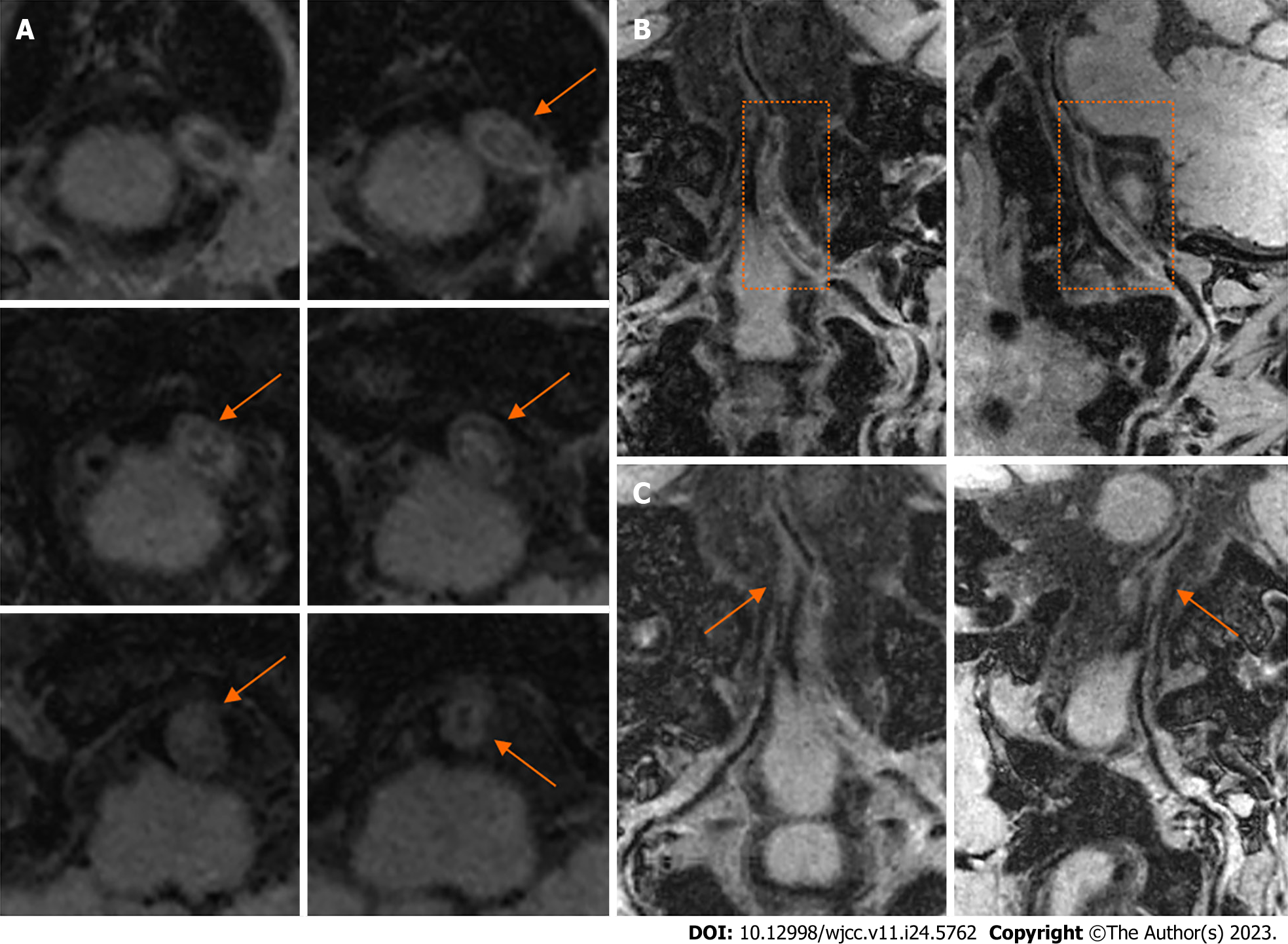
Figure 3 The high-resolution magnetic resonance imaging of bilateral vertebral arteries.
A: The T1-weighted sequence of several axial levels of the left intracranial vertebral artery (VA) showed mixed equal, slightly low, and slightly high signal intensity in the occluded VA lumen, with obvious wall thickening (orange arrows); B: The curved planar reformation (CPR) images of left VA showed long-range thrombosis, lumen occlusion, and wall thickening (orange dashed zones); C: The CPR images showed occlusion of the right intracranial VA (orange arrows).
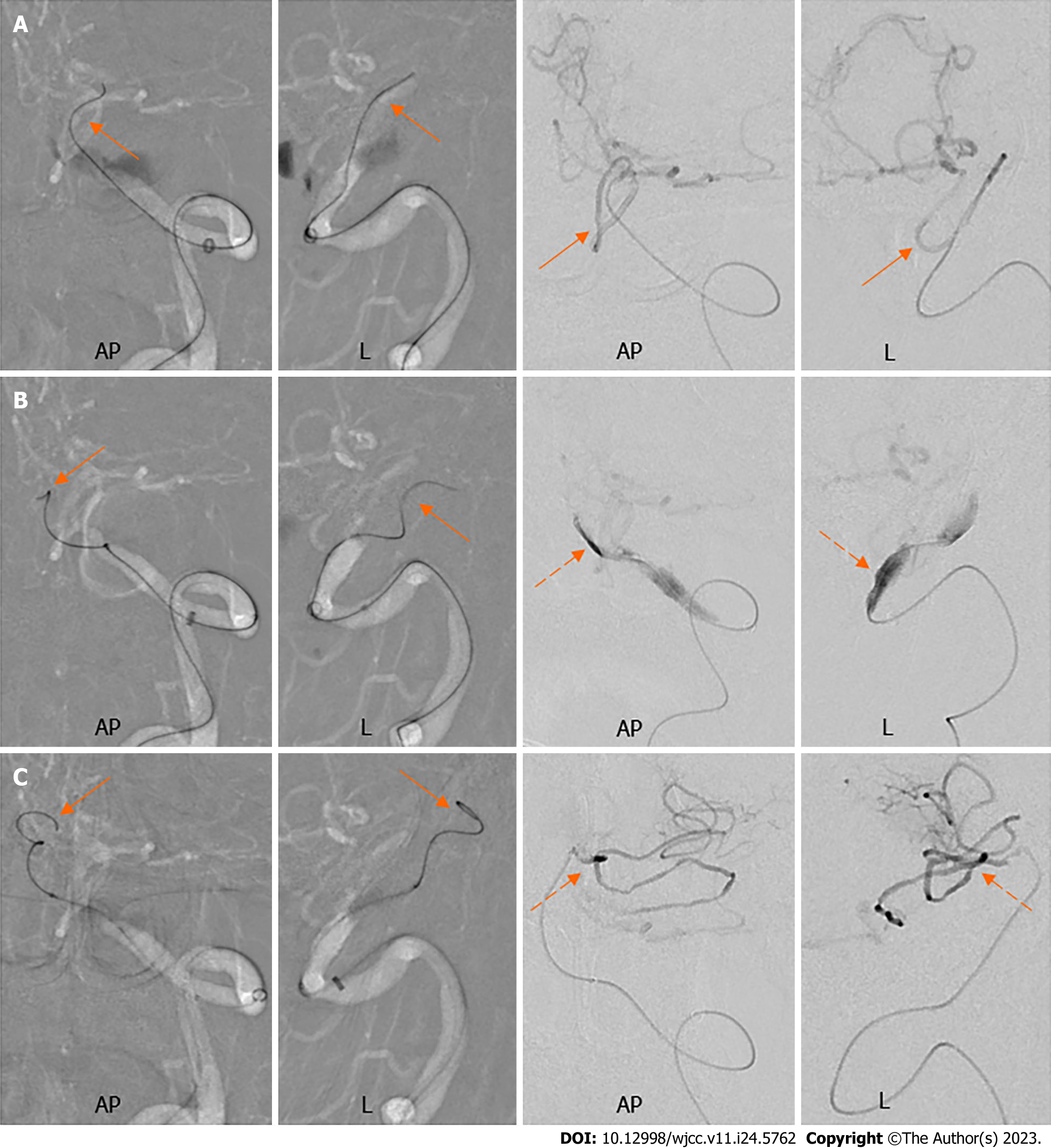
Figure 4 The course of microwire in the subintima and microcatheter angiography.
A: The microwire entered the posterior inferior cerebellar artery (orange arrows); B: The microwire advanced in a sigmoid curve in the subintima (orange arrows) and the microcatheter angiography identified the subintimal dissection (orange dashed arrows); C: The subintimal microwire kept advancing in a spiral shape (orange arrows) and the microcatheter angiography showed the microwire entered the anterior inferior cerebellar artery (orange dashed arrows). AP: Anterior-posterior; L: Lateral.
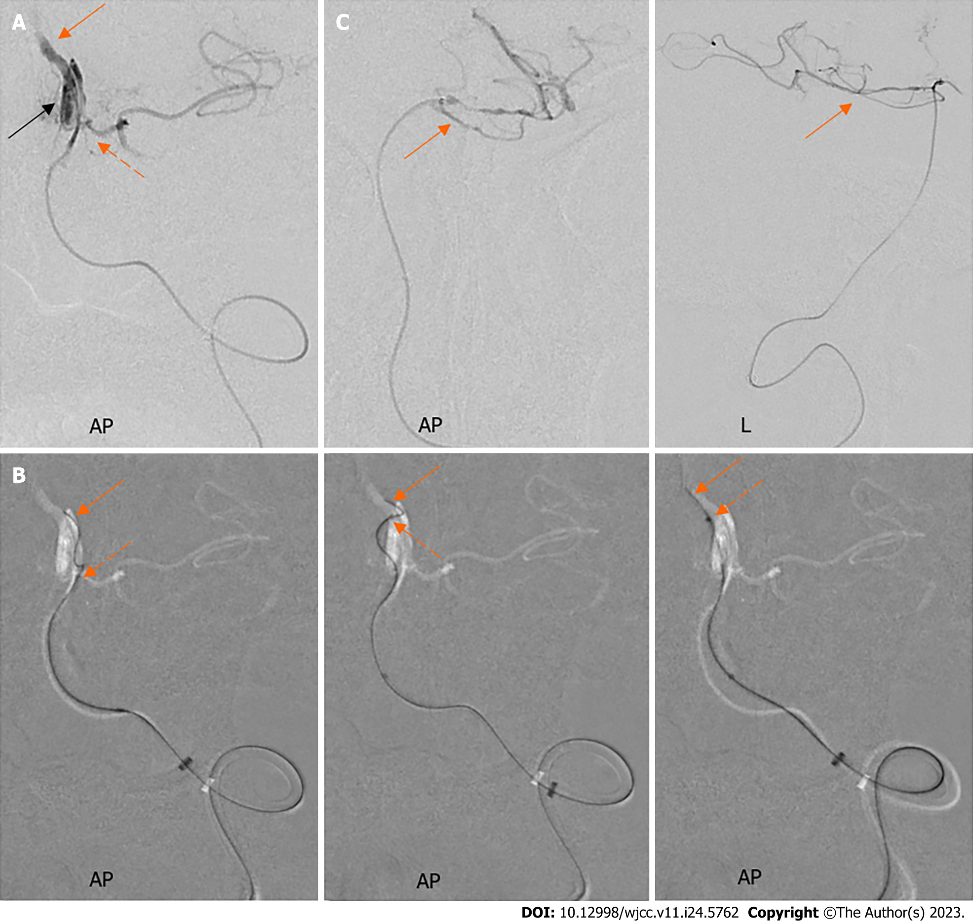
Figure 5 The subintimal microwire re-entered the true lumen.
A: The microcatheter angiography at the level of anterior inferior cerebellar artery (AICA) orifice revealed the true lumen’s position (orange arrow), the AICA branch (the orange dashed arrow), and the subintimal “tubular” dissection (black arrow); B: Under the guidance of a roadmap, the microwire (orange arrows) and the microcatheter (the orange dashed arrows) were manipulated to re-enter the true lumen; C: The microcatheter angiography showed the microwire was advanced to the superior cerebellar artery (orange arrows). AP: anterior-posterior; L: lateral.
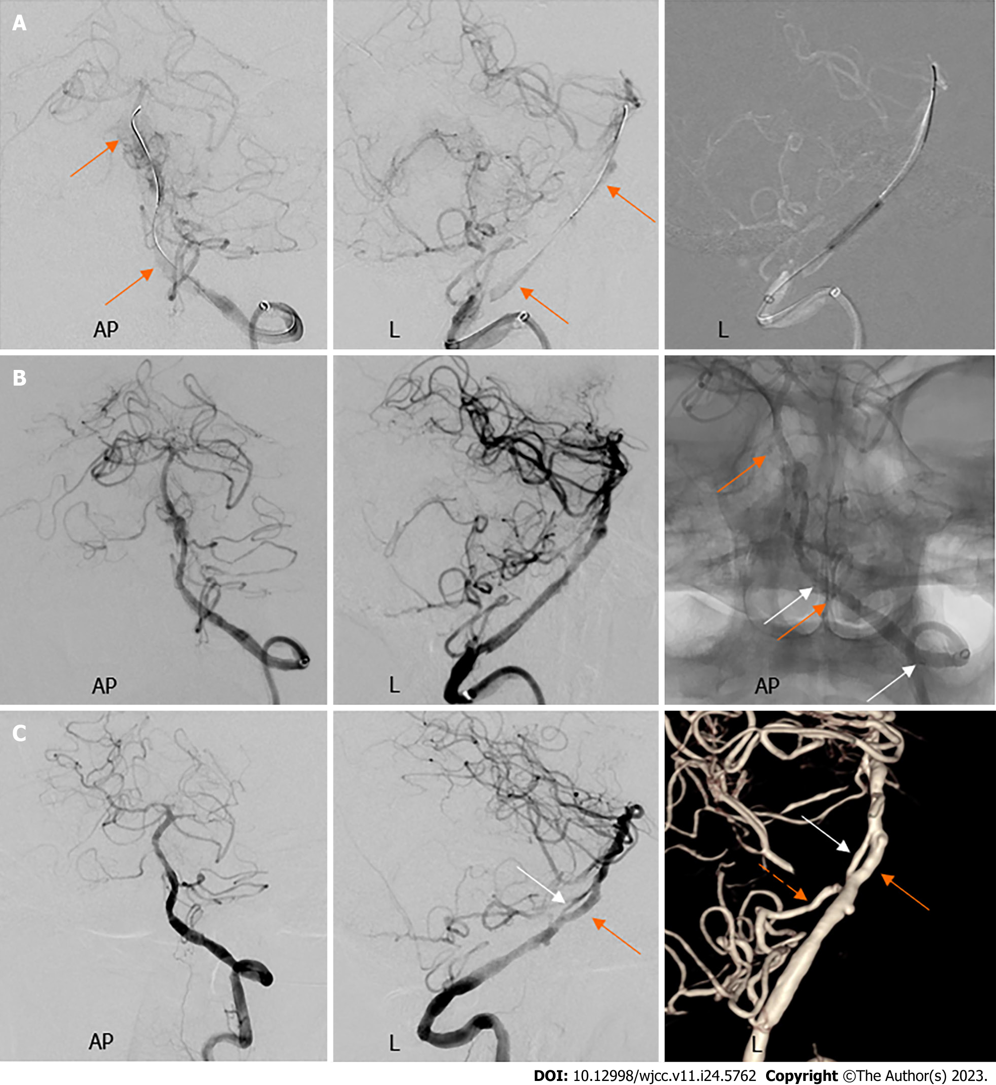
Figure 6 Cerebral angiography of left vertebral artery before balloon dilatation, after stent implantation and at three months postoperatively.
A: Digital subtraction angiography (DSA) before balloon dilatation showed the subintimal canal (orange arrows); B: Angiography revealed reconstruction of the left vertebral artery after implantation of two stents, with four stent markers visible on fluoroscopy (orange and white arrows); C: Follow-up DSA revealed that a residual true lumen (white arrows) was seen in parallel with the subintimal canal (orange arrows) far from the left anterior inferior cerebellar artery (orange dashed arrows), giving the impression of fenestration. AP: Anterior-posterior; L: Lateral.
- Citation: Fu JF, Zhang XL, Lee SY, Zhang FM, You JS. Subintimal recanalization for non-acute occlusion of intracranial vertebral artery in an emergency endovascular procedure: A case report. World J Clin Cases 2023; 11(24): 5762-5771
- URL: https://www.wjgnet.com/2307-8960/full/v11/i24/5762.htm
- DOI: https://dx.doi.org/10.12998/wjcc.v11.i24.5762


