Copyright
©The Author(s) 2023.
World J Clin Cases. May 26, 2023; 11(15): 3522-3532
Published online May 26, 2023. doi: 10.12998/wjcc.v11.i15.3522
Published online May 26, 2023. doi: 10.12998/wjcc.v11.i15.3522
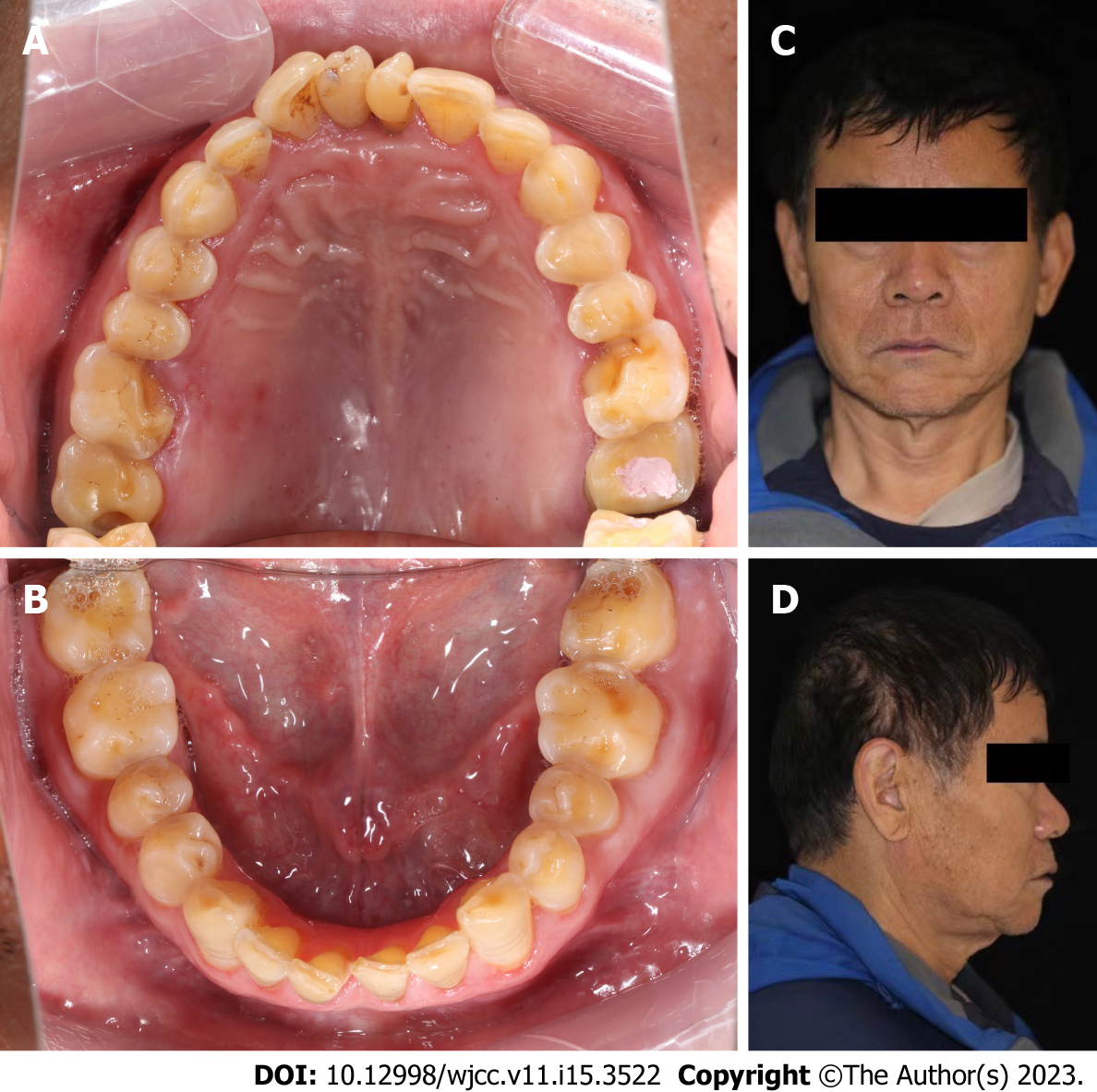
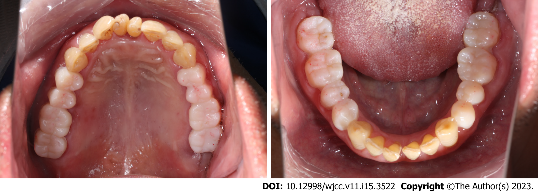
Figure 1 Photo taken before occlusion reconstruction.
A and B: Initial intraoral photographs; C and D: Initial face photograph.
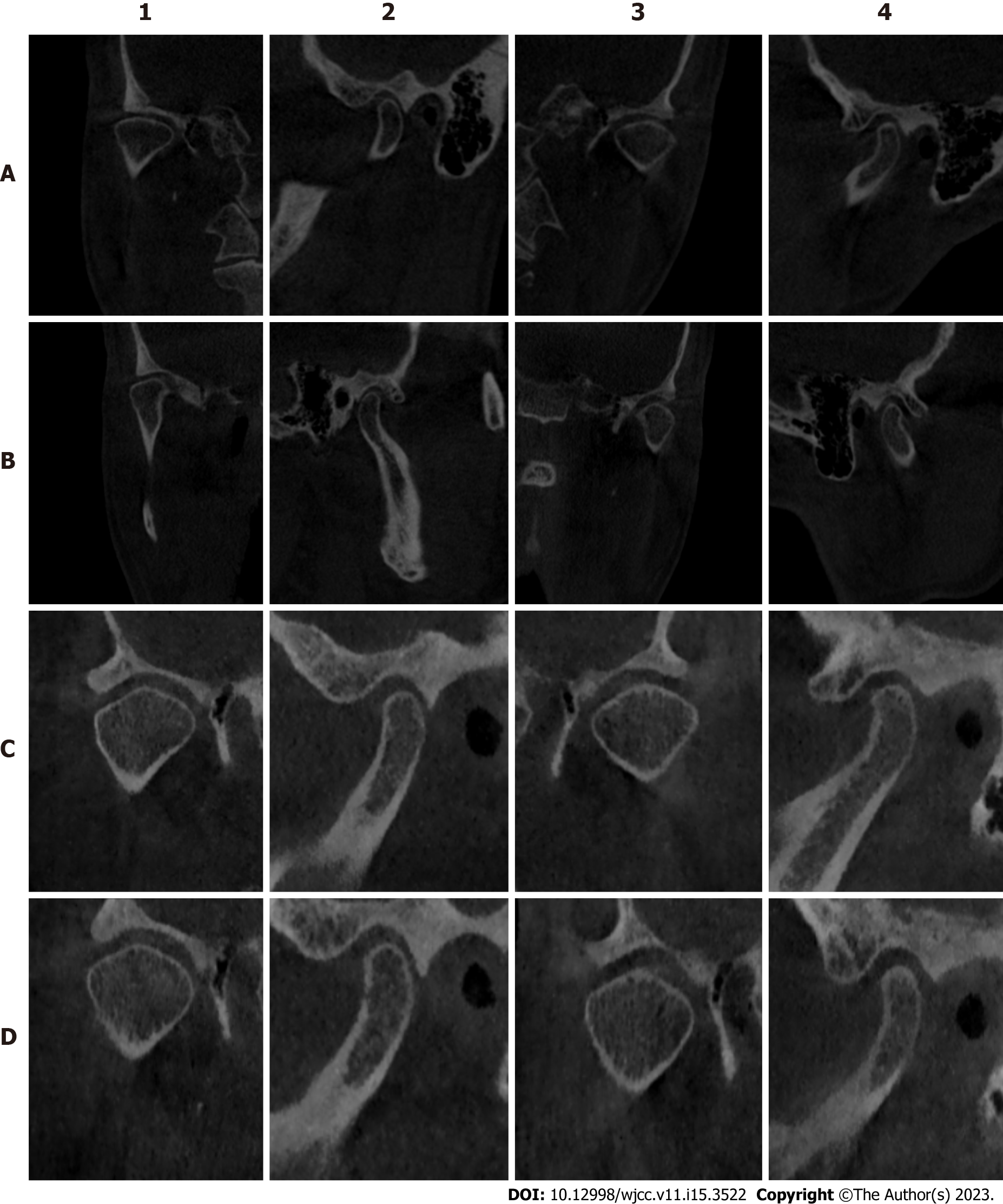
Figure 2 Cone beam computed tomography imaging.
A: Cone beam computed tomography (CBCT) at the beginning; B: CBCT after wearing an occlusal pad for 3 mo; C: CBCT 1 mo after wearing the temporary crown; D: CBCT rechecked 2 wk after wearing the final denture. 1 and 2 are the coronal and sagittal planes of the right temporomandibular joint, respectively; 3 and 4 are the coronal and sagittal planes of the left temporomandibular joint, respectively.
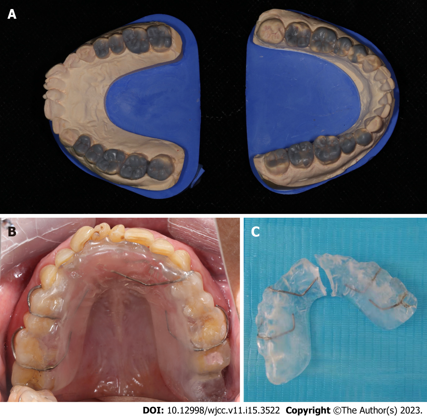
Figure 3 Preparation before restoration.
A: Diagnostic wax pattern; B: Intraoral photographs of patients wearing maxillary occlusal pad; C: Divide the occlusal pad at the center line for standby.
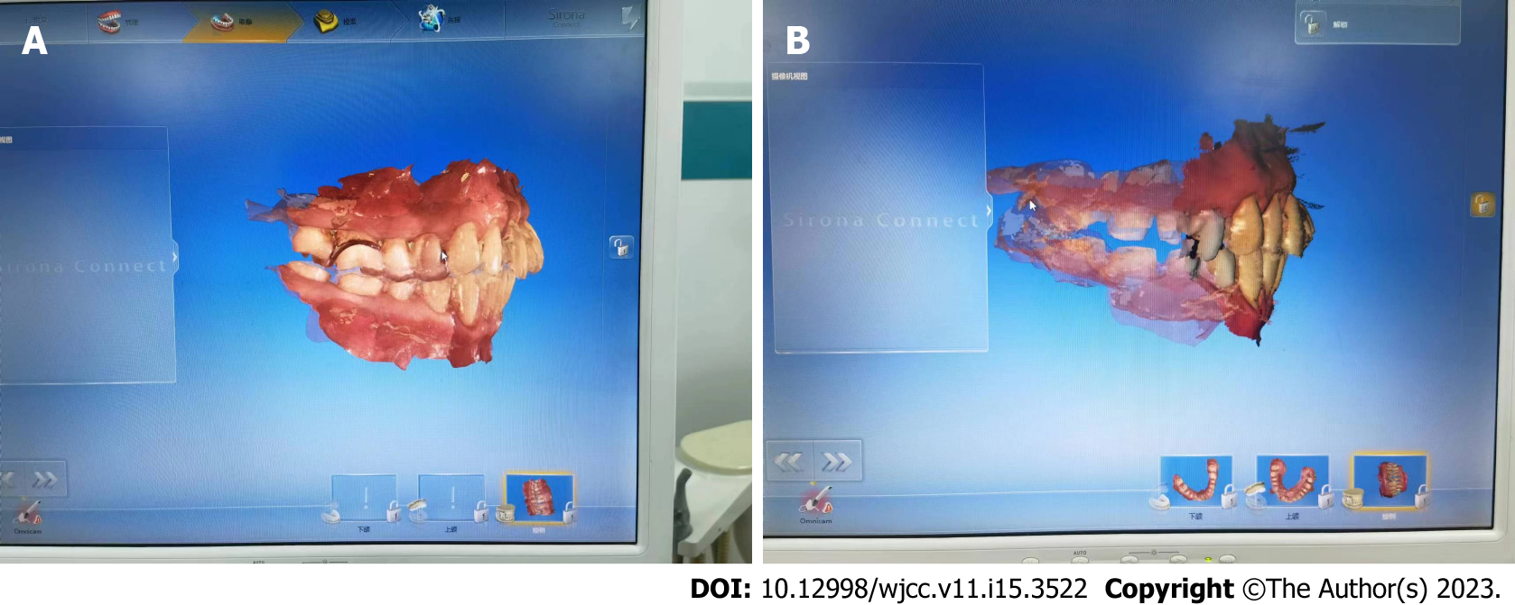
Figure 4 Occlusal reconstruction models obtained through digital intraoral scanning.
A: Digital intraoral scanning with occlusal pad; B: Digital intraoral scanning after fine tooth preparation.
Figure 5 Intraoral photographs of temporary crowns worn on the preliminary prepared posterior teeth.
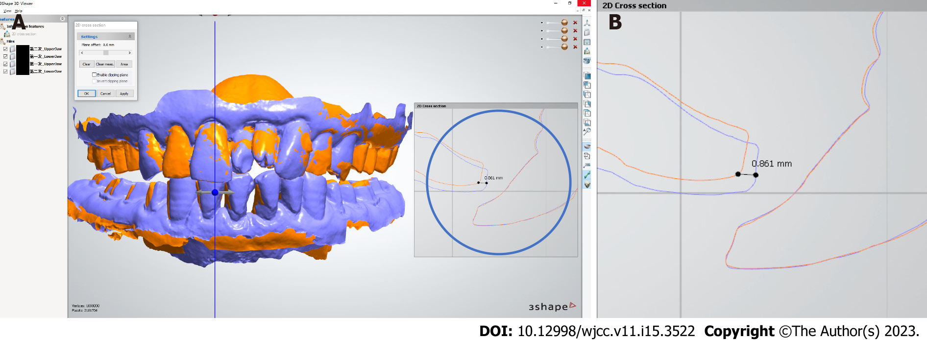
Figure 6 Selection of the final occlusal relationship.
A: Comparison of maxillary position between the end of occlusal pad and the end of mock up; B: A local magnified image showing that at the end of the mock up phase, compared to when wearing the occlusal pad, the most anterior end of the lateral labial margin of the mandibular central incisor is shifted upward and medially by approximately 0.861 mm.
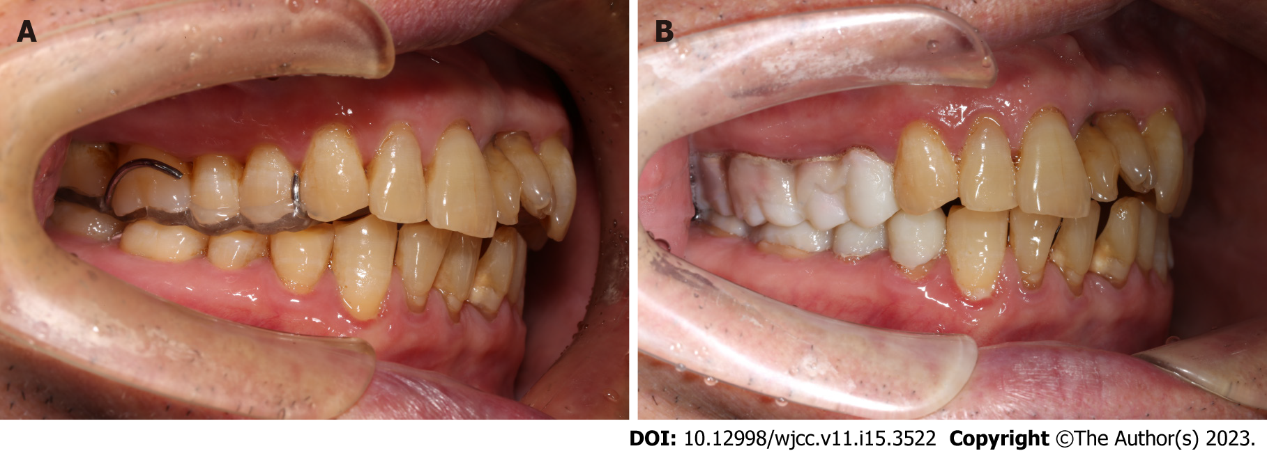
Figure 7 Comparison of anterior tooth overjet photographs.
A: Anterior tooth overjet photographs at occlusal pad end-stage; B: Anterior tooth overjet photographs at temporary coronal end-stage.
- Citation: Hou C, Zhu HZ, Xue B, Song HJ, Yang YB, Wang XX, Sun HQ. New clinical application of digital intraoral scanning technology in occlusal reconstruction: A case report. World J Clin Cases 2023; 11(15): 3522-3532
- URL: https://www.wjgnet.com/2307-8960/full/v11/i15/3522.htm
- DOI: https://dx.doi.org/10.12998/wjcc.v11.i15.3522


