Copyright
©The Author(s) 2022.
World J Clin Cases. Sep 6, 2022; 10(25): 8893-8905
Published online Sep 6, 2022. doi: 10.12998/wjcc.v10.i25.8893
Published online Sep 6, 2022. doi: 10.12998/wjcc.v10.i25.8893
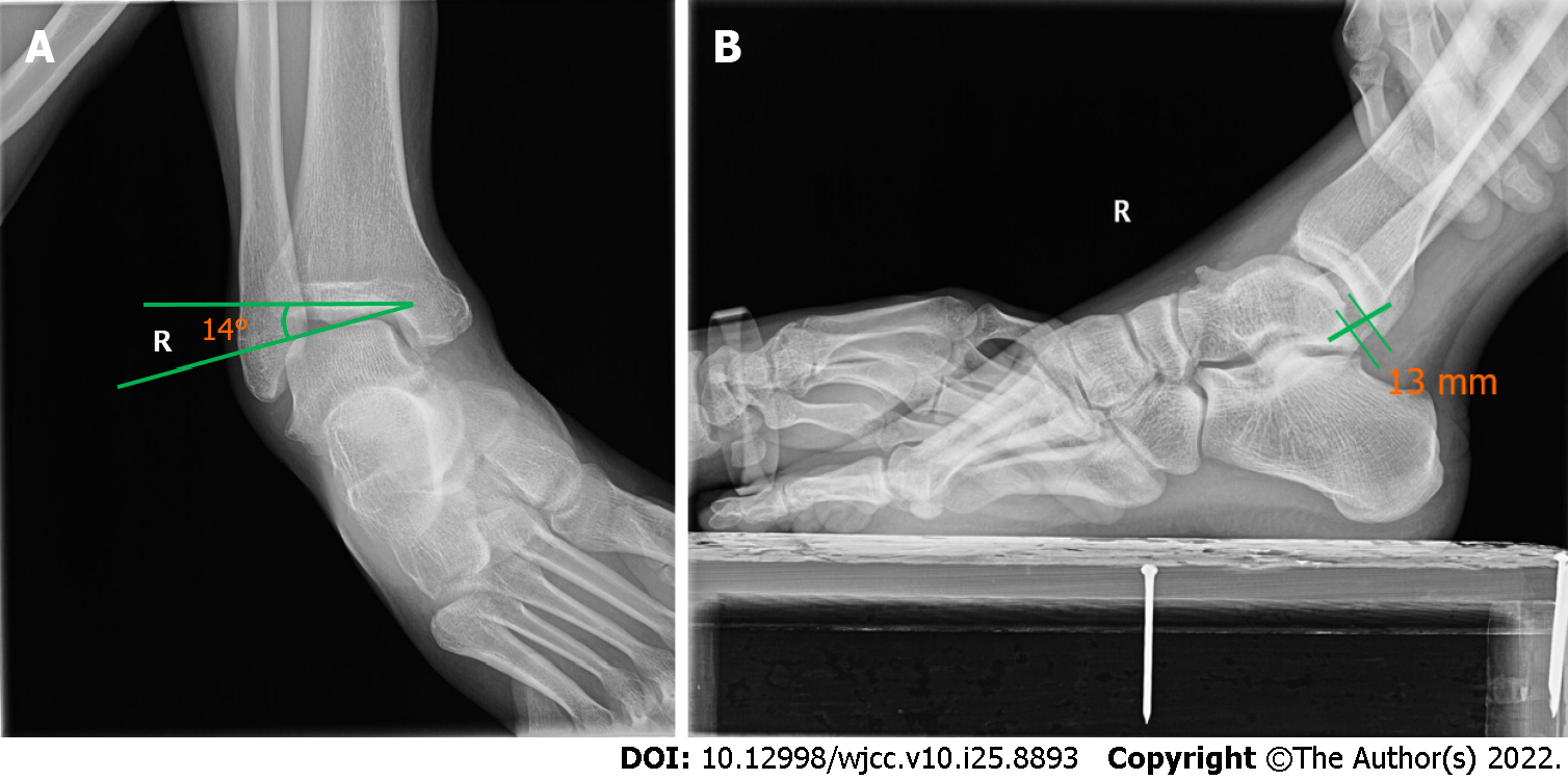
Figure 1 Stress radiographic views.
A: Talar tilt test; B: Anterior drawer test.
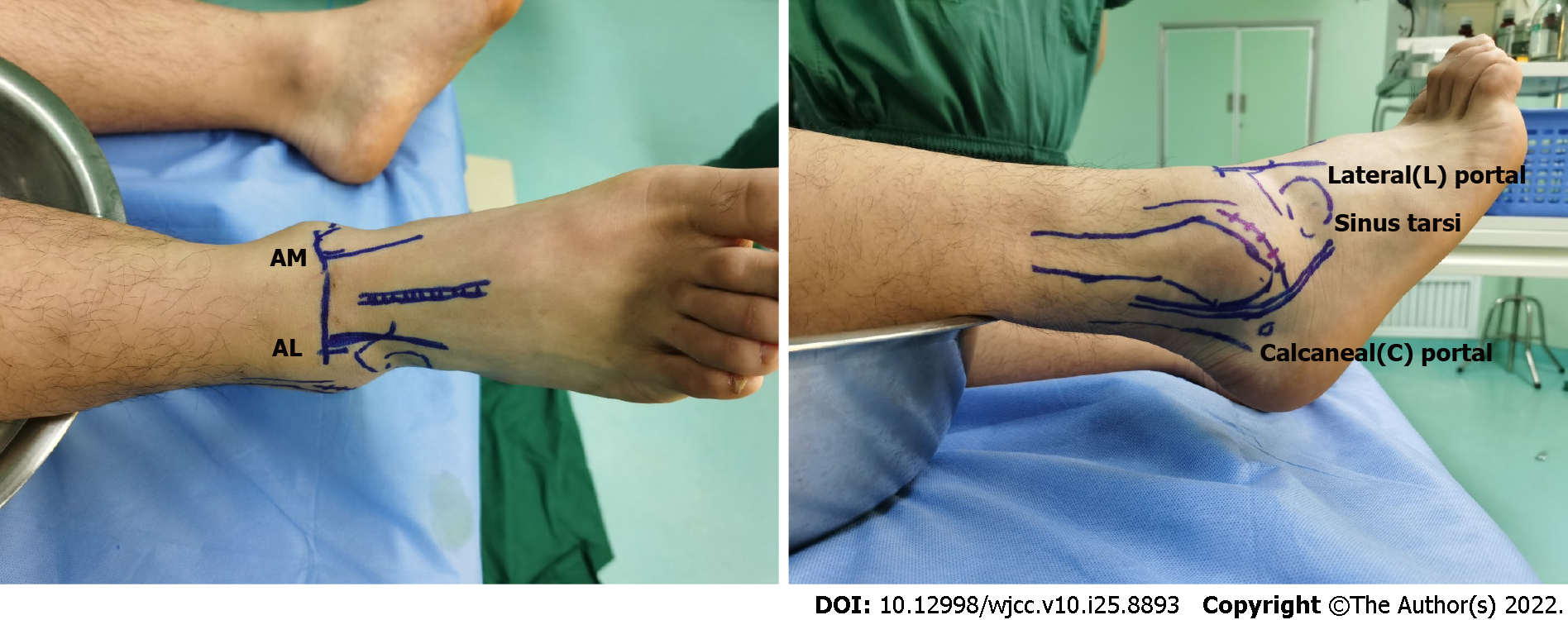
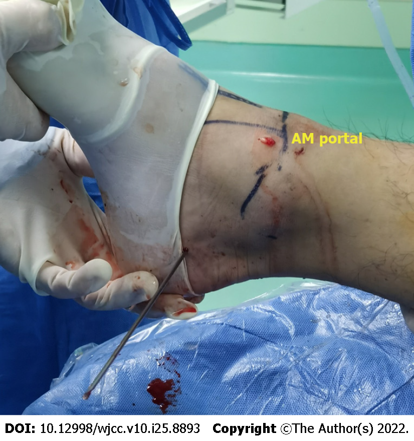
Figure 2 The patient was placed in the supine position.
This shows anatomic landmarks drawn on the patient's skin before anesthesia administration, including the anteromedial portal (AM), anterolateral portal (AL), and lateral portal.
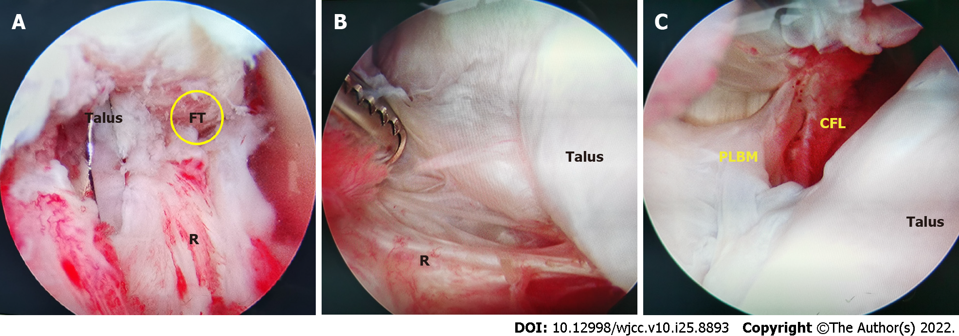
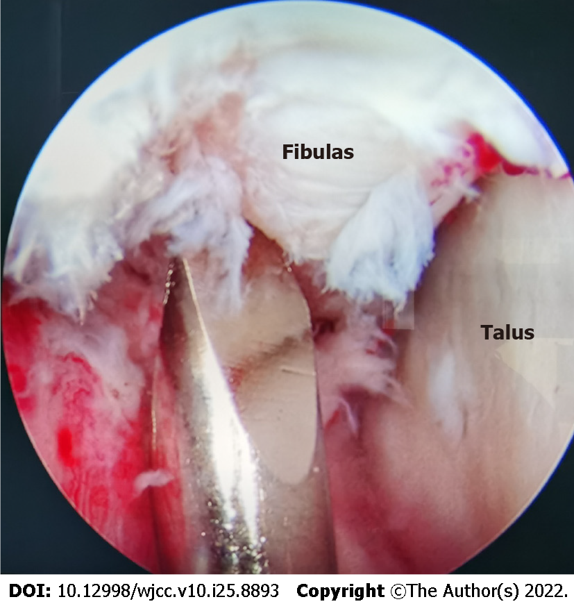
Figure 3 Its distal adjacent was the proximal insertion of the calcaneo-fibular ligament.
A: Anterior routine medial and lateral arthroscopy estimated the remnant of the anterior talofibular ligament (ATFL) and found the ATFL footprint, and the quality of the ATFL rennant was poor; B: The ankle joint was inspected and any intra-articular disorders were assessed and managed, with shaving off of inflamed synovial membr ane, microfracture for cartilage injuries and excision of the osteophytes; C: Continuing to explore downward from the talofibular space, the peroneus longus and brevis muscles and calcaneo-fibular ligament (CFL); CFL was thin and hyperemic. PLBM: Peroneus longus and brevis muscles.
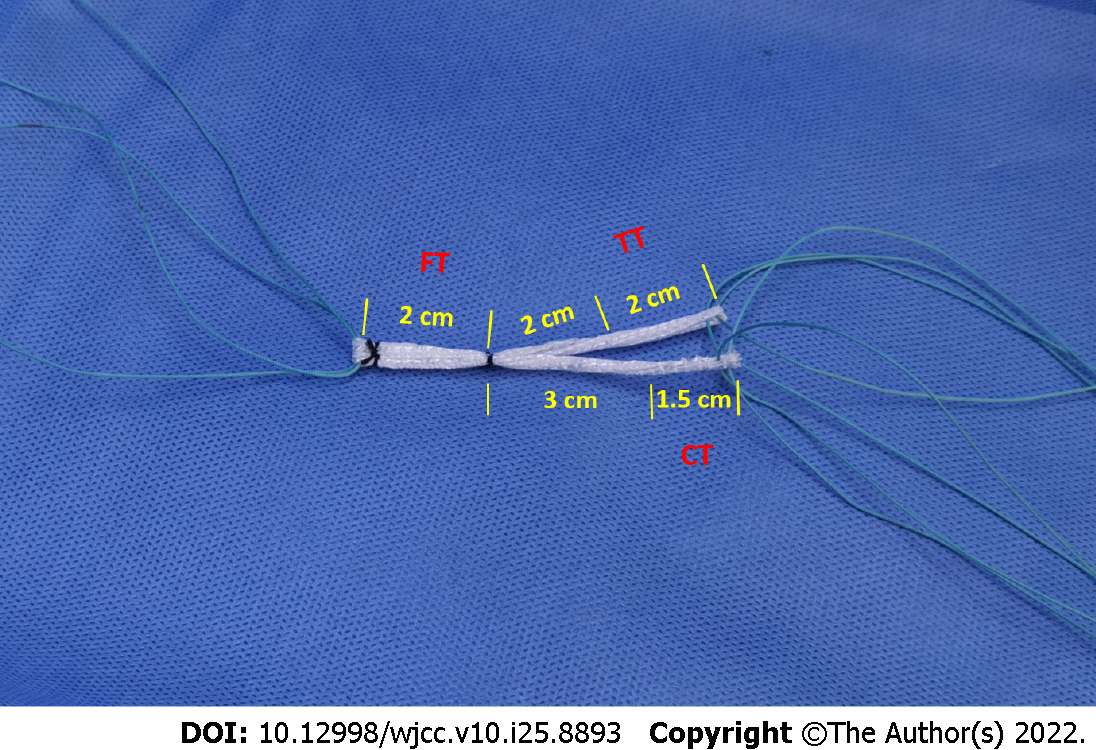
Figure 4 Preparation of the ligament advanced reinforcement system artificial ligament.
Ligament advanced reinforcement system artificial ligament tumor strip patch was constructed with an anatomical Y configuration with a diameter of approximately 3 mm. FT: Fibular bone tunnel; CT: Calcaneal bone tunnel; TT: Talar bone tunnel.
Figure 5 Exit point of calcaneal bone tunnel.
A guide pin allowed us to drill a 3.0-mm diameter calcaneal tunnel from the calcaneal footprint to the anterior medial edge of the calcaneal tuberosity. AM: Anteromedial.
Figure 6 The guide pin located the footprint of the anterior talofibular ligament and calcaneo-fibular ligament and drilled an oblique fibular tunnel of 3.
0 mm diameter with the cartilage edge. PLBM: Peroneus longus and brevis muscles.
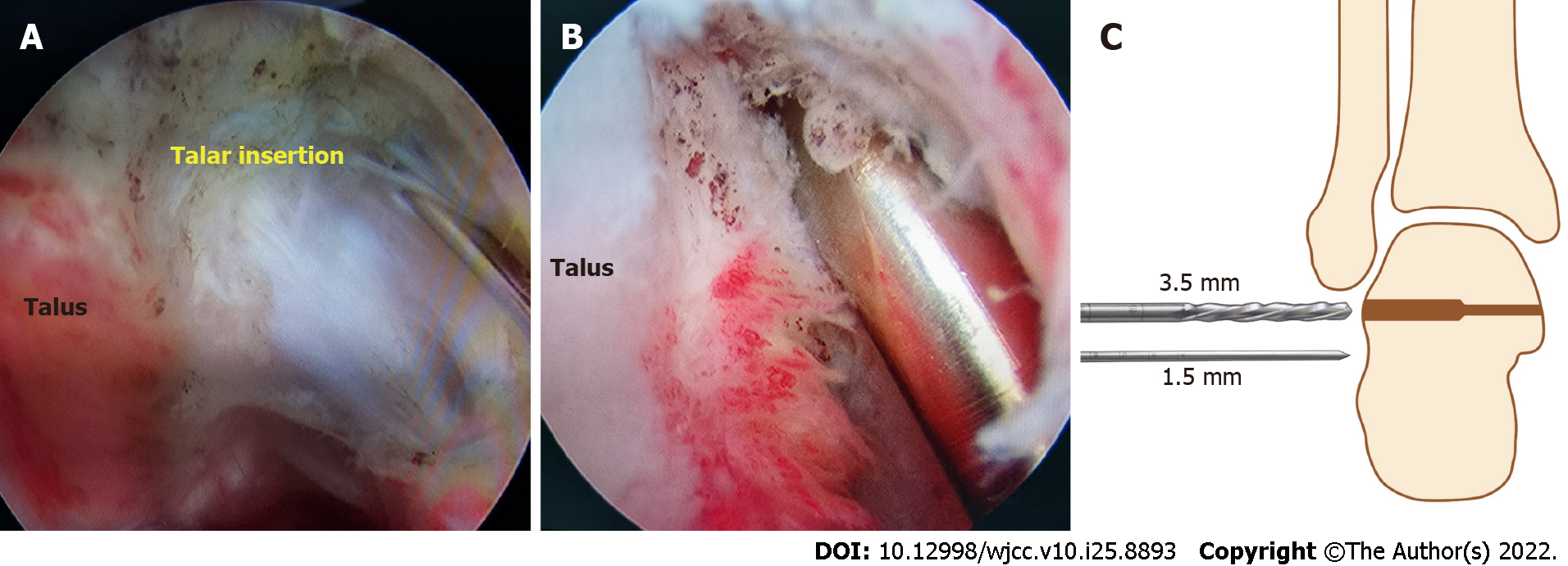
Figure 7 We drilled the talar tunnel under monitoring of the anterolateral portal.
A: The tunnel entrance was located at the talar footprint of the anterior talofibular ligament, which was below the triangular region of the talus on the midpoint between the superolateral edge of the talar body and the subtalar joint; B: We drilled a 3 mm × 20 mm talar tunnel at the anatomical insertion; C: The length of the tunnel was strictly controlled within 20 mm.
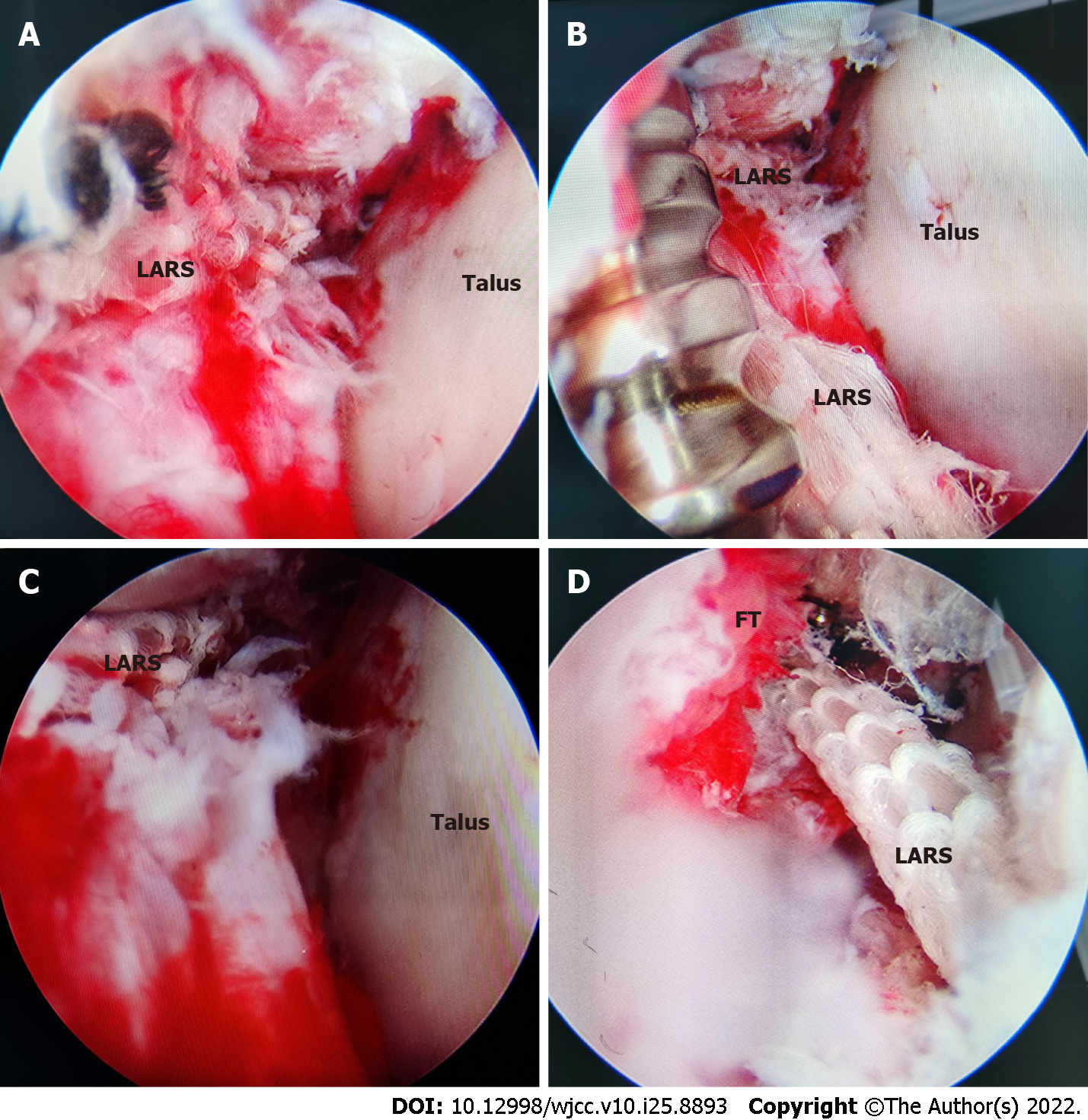
Figure 8 The last step corresponded to the positioning and fixation of the graft.
A: Through the lead through-line method, the high-strength suture of ligament advanced reinforcement system (LARS) was passed through the calcaneal tunnel, and the calcaneal stem of LARS was introduced, and the talar and fibular stems were also introduced into their respective bone tunnels; B: The fibular stem of LARS was fixed with a metal extrusion screw; C: The suture of the calcaneal stem was stretched and tensioned in the neutral position of the ankle, and the LARS of the calcaneal stem was fixed with a metal extrusion screw through the calcaneal incision; D: The suture of the talar stem was tensioned in the mild valgus position of the ankle, and the LARS of the talar stem was fixed with a metal extrusion screw through the lateral incision. FT: Fibular bone tunnel.
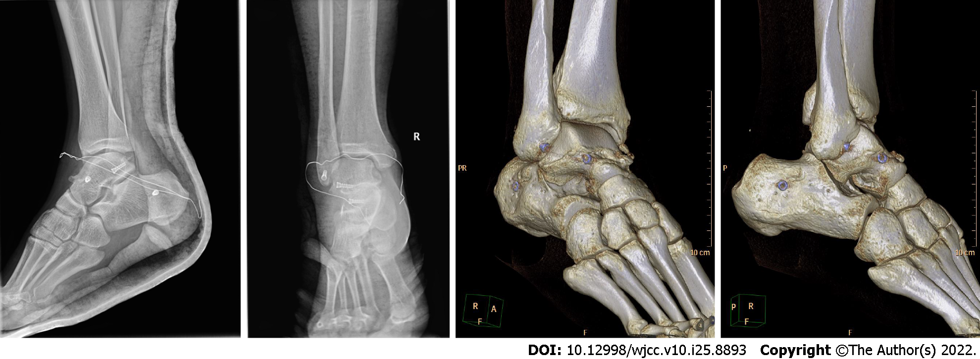
Figure 9 On the 3rd day after operation, the positive and lateral X-ray examination showed that the ankle was immobilized in a neutral position with short leg plaster, and three metal extrusion screws could be seen through three- dimensional computed tomography.
- Citation: Wang Y, Zhu JX. Arthroscopic anatomical reconstruction of lateral collateral ligaments with ligament advanced reinforcement system artificial ligament for chronic ankle instability. World J Clin Cases 2022; 10(25): 8893-8905
- URL: https://www.wjgnet.com/2307-8960/full/v10/i25/8893.htm
- DOI: https://dx.doi.org/10.12998/wjcc.v10.i25.8893


