Copyright
©2014 Baishideng Publishing Group Inc.
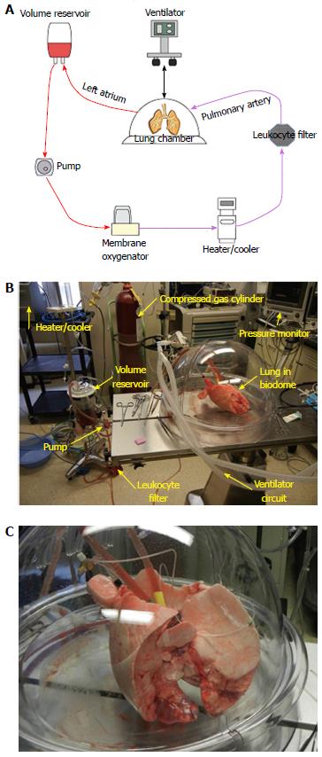
Figure 1 This diagram depicts a schematic of a large animal (porcine) ex vivo lung perfusion circuit (A), the portable stand for the perfusion pump (B), A close up picture of a porcine lung on an ex vivo lung perfusion circuit (C).
The ventilator is used to expand the lungs with lung protective ventilation strategies. The volume reservoir contains the perfusates (either sanguineous or acelluar). Centrifugal pumps have the advantage of being able to have the afterload varied and have the circuit clamped easily, which is a challenge with roller pumps. The heater/cooler allows for exact temperature titration. The reservoir, centrifugal pump, membrane oxygenator, and leukocyte filter are all contained on this apparatus. The biodome which houses the large animal lung is visualized with the ventilator circuit attached to the endotracheal tube which directly cannulates the trachea. The inflow and outflow cannulas are at the superior aspect of the lung and the endotracheal tube on image top left.
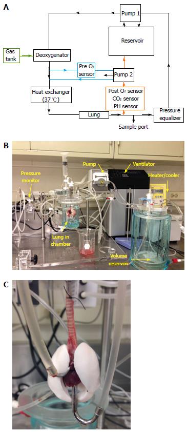
Figure 2 This diagram depicts a schematic of a small animal (rat) ex vivo lung perfusion circuit (A), the small animal perfusion circuit (B); a close-up of a rat lung undergoing ex vivo perfusion (C).
Many of the same characteristics that are in the large animal circuit are present. This particular circuit has the ability for fine measurements of pressure, flow, and weight. The image back right shows the thermoregulator and the ventilator. The perfusates reservoir is in the image front right. The small animal circuit is analogous to the large animal circuit. However, due to the relative scale of the organ to the circuit, the perfusate volume needed for a complete perfusion is less. In addition, the ability to perform positive as well as negative pressure ventilation is possible. This varied ventilation an mimic both the mechanical breathing as well as natural intrathoracic breathing. The tracheal cannulation is top-center. The inflow cannula going into the pulmonary artery is from top-left and the outflow cannula going across the left atrium through the left ventricular apex is on screen right.
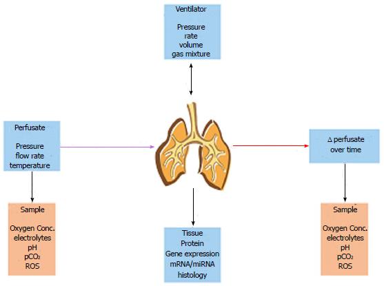
Figure 3 Diagram of what is able to be able to be measured and varied with the ex vivo perfusion circuit.
This figure directly correlates with Table 1.
-
Citation: Nelson K, Bobba C, Ghadiali S, Jr DH, Black SM, Whitson BA. Animal models of
ex vivo lung perfusion as a platform for transplantation research. World J Exp Med 2014; 4(2): 7-15 - URL: https://www.wjgnet.com/2220-315X/full/v4/i2/7.htm
- DOI: https://dx.doi.org/10.5493/wjem.v4.i2.7


