


Published online Apr 18, 2024. doi: 10.5312/wjo.v15.i4.321
Peer-review started: December 30, 2023
First decision: January 16, 2024
Revised: January 28, 2024
Accepted: March 25, 2024
Article in press: March 25, 2024
Published online: April 18, 2024
Processing time: 107 Days and 17.5 Hours
The four components that make up the current dual-mobility artificial hip joint design are the femoral head, the inner liner, the outer liner as a metal cover to prevent wear, and the acetabular cup. The acetabular cup and the outer liner were constructed of 316L stainless steel. At the same time, the inner liner was made of ultra-high-molecular-weight polyethylene (UHMWPE). As this new dual-mobility artificial hip joint has not been researched extensively, more tribological research is needed to predict wear. The thickness of the inner liner is a significant compo
To make use of finite element analysis to gain a better understanding of the contact behavior in various inner liner thicknesses on a new model of a dual-mobility artificial hip joint, with the ultimate objective of determining the inner liner thickness that was most suitable for this particular type of dual-mobility artificial hip joint.
In this study, the size of the femoral head was compared between two diameters (28 mm and 36 mm) and eight inner liner thicknesses ranging from 5 mm to 12 mm. Using the finite element method, the contact parameters, including the maximum contact pressure and contact area, have been evaluated in light of the Hertzian contact theory. The simulation was performed statically with dissipated energy and asymmetric behavior. The types of interaction were surface-to-surface contact and normal contact behavior.
The maximum contact pressures in the inner liner (UHMWPE) at a head diameter of 28 mm and 36 mm are between 3.7-13.5 MPa and 2.7-10.4 MPa, respectively. The maximum von Mises of the inner liner, outer liner, and acetabular cup are 2.4–11.4 MPa, 15.7–44.3 MPa, and 3.7–12.6 MPa, respectively, for 28 mm head. Then the maximum von Mises stresses of the 36 mm head are 1.9-8.9 MPa for the inner liner, 9.9-32.8 MPa for the outer liner, and 2.6-9.9 MPa for the acetabular cup. A head with a diameter of 28 mm should have an inner liner with a thickness of 12 mm. Whereas the head diameter was 36 mm, an inner liner thickness of 8 mm was suitable.
The contact pressures and von Mises stresses generated during this research can potentially be exploited in estimating the wear of dual-mobility artificial hip joints in general. Contact pressure and von Mises stress reduce with an increasing head diameter and inner liner’s thickness. Present findings would become one of the references for orthopedic surgery for choosing suitable bearing geometric parameter of hip implant.
Core Tip: The dual mobility hip system has the potential to be a great big bearing articulation if its technology is combined with highly cross-linked polyethylene. The modern artificial hip joint design has two free articulations between four parts: the femoral head, the inner liner, the outer liner as a metal cover to reduce wear, and the acetabular cup. Several studies show that prosthetic implant wear might be predicted partly by computing contact pressure distribution and contact area during everyday activities. A more reliable method of distinguishing between ideal and reality models may be incorporating activities with severe loading and boundary conditions.
- Citation: Hidayat T, Ammarullah MI, Ismail R, Saputra E, Lamura MDP, K N C, Bayuseno AP, Jamari J. Investigation of contact behavior on a model of the dual-mobility artificial hip joint for Asians in different inner liner thicknesses. World J Orthop 2024; 15(4): 321-336
- URL: https://www.wjgnet.com/2218-5836/full/v15/i4/321.htm
- DOI: https://dx.doi.org/10.5312/wjo.v15.i4.321
Bousquet pioneered the idea of a dual-mobility (DM) artificial hip joint (AHJ) in the 1970s[1]. The polyethylene liner of the dual mobility system is concave on the inside for internal movement and convex on the outside for external motion. The design uses efficient large bearings to replicate metal-on-metal (MoM) articulation[2,3]. The use of highly cross-linked polyethylene bearings has grown, and preliminary findings have been shared[4,5]. They have low initial wear rates, meaning less osteolysis and a longer implant lifespan[4-6]. The dual mobility hip system has the potential to be a great big bearing articulation if its technology is combined with highly cross-linked polyethylene[7]. Having two options for movement should keep things stable and retain most of the range of motion[8-10].
The modern artificial hip joint design has two free articulations between four parts: the femoral head, the inner liner, the outer liner as a metal cover to reduce wear, and the acetabular cup (Figure 1). This geometric shape was introduced by the Center for Biomechanics Biomaterials Biomechatronics and Biosignal Processing (CBIOM3S), Department of Mechanical Engineering, Universitas Diponegoro, Semarang, Indonesia, and has received a patent from the Ministry of Law and Human Rights of the Republic of Indonesia with patent number S00201703018. The range of motion (RoM) of this design is projected to be greater than that of single-mobility (SM) devices with a similar-sized head[9]. This wider RoM is needed by Asians to carry out their daily activities, especially worship activities[11-14]. Additionally, it may shield the convex ultra-high-molecular-weight polyethylene (UHMWPE) liner’s surface from wear. The DM’s metal cover (namely the outer liner) shields the inner liner from damage as it slides into the cup. Several research projects have been carried out on this novel DM AHJ[15-18]. Despite this, further study is still required, particularly on the tribological traits that might be used to quantify wear. Obviously, it helps to verify the findings and develop the method based on the work of others.

Although conducting experiments on contact mechanics using hip joint simulators is a common method, finite element analysis (FEA) is also a good choice for predicting contact pressure in hip joints[19]. Several studies[20-22] show that prosthetic implant wear might be predicted partly by computing contact pressure distribution and contact area during everyday activities. Using the finite element method, the contact parameters, including the maximum contact pressure and contact area, have been evaluated in light of the Hertzian contact theory[20,21].
The stresses encountered at the contact surfaces may dictate the wear processes and hence may be connected to the wear volume and particle size, making knowledge of the contact mechanics of a prosthetic bearing crucial. In order to evaluate the bearing’s structural integrity and prevent undesirable outcomes such as equatorial contacts and the femoral head being gripped by the acetabular cup, it is essential to compare the contact stresses to the strength of the bearing materials[23].
Due to the novelty of the DM AHJ model, limited study has been conducted on it. An investigation is required to identify the inner liner thickness of this DM AHJ in the most optimal manner. This study aims to utilize finite element analysis to learn more about the contact behavior of varying inner liner thicknesses on a novel model of DM AHJ, with the end goal of determining the optimal inner liner thickness for this particular DM AHJ. The femoral head is measured and compared between two sizes in this study: small head (28 mm) and big head (36 mm). Eight inner liner thicknesses range from 5 mm to 12 mm. Contact pressures and von Mises stresses, determined in this work, may be utilized to estimate the wear and the failure of DM AHJ in general.
The outer liner and the acetabular cup were stainless steel 316L (SS316L) in this investigation. The inner liner was made of UHMWPE. Finite element software, Abaqus, was used for static analysis. The elastic modulus of SS316L was 200000 MPa[24], whereas that of UHMWPE was just 1000 MPa[25]. SS316L and UHMWPE had Poisson’s ratios of 0.3[24] and 0.4[25], respectively. The following were the technical specs of the rig used for this FEA: Processor (Intel Xeon E5 2698 v3), Memory (64 GB), and Graphics Adapter (VGA): Quadro P2000 from Nvidia.
The femoral head had a diameter of 28 mm, representing the “small head” , and 36 mm representing the “big head” . In AHJ, these are the typical sizes utilized. The thickness of the inner liner varied from 5 mm to 12 mm over a total of eight distinct options. Dubin’s research on dual-mobility sizes accommodates the inner liner thicknesses of this order[26]. Radial clearance adopted from Hidayat et al[18], where inner liner and the head was 150 μm, while the clearance between the outer liner and the cup was 50 μm. One millimeter thick described the outer liner, and two millimeters described the acetabular cup[18].
The materials were thought to be isotropic, homogenous, and linear elastic[27]. In order to speed up the FEA while maintaining the same level of precision, the femoral head was modeled as an analytical rigid body[28]. With a butterfly mesh model based on an open cube box concept[29], the inner liner was meshed using eight-node structural hexahedron elements (C3D8R), which eliminated the need for a combination of tetrahedral and hexahedral elements and the resulting potential for irregular stress concentrations[30]. The outer liner and acetabular cup used the quadratic tetrahedral (C3D10H) mesh model to avoid errors in visualizing contact pressure. Distinguishing the mesh model on the outer liner and inner liner is also done by Wegrzyn et al[31]. The FEA model for DM AHJ used in this work is shown in Figure 2.

The output of quadratic shape functions is less impacted by mesh refinement, thus offering a better approximation of the underlying geometry. They are also more stable. These advantages are because quadratic shape functions have a higher degree of quadraticity[32]. With fewer elements, quadratic elements may morph more convincingly and accurately depict geometric curvature. Quadratic elements can also deform more correctly and realistically than linear ones[33].
The mesh convergence test yielded the proper mesh size for the simulation, which was 0.8 mm for hexahedral and 1.5 mm for tetrahedral (Figure 3). On the head of 28 mm and 36 mm, the inner liner’s elements were between 19596–68430 and 28800–100800, respectively. The number of elements often used in finite element (FE) simulations are 8352[34], 6912[35], 6800–15500[36], and 3864[37]. Therefore, the number of elements in this study is sufficient and valid for FE simu

| Components | Materials | Element types | Number of elements (range)1 | Number of nodes (range)1 |
| 28 mm femoral head | ||||
| Femoral head | analytical rigid body | |||
| Inner liner | UHMWPE | Hexahedral (C3D8R) | 19596–68430 | 23331–74256 |
| Outer liner | SS316L | Tetrahedral (C3D10H) | 6552–12147 | 13317–24557 |
| Acetabular cup | SS316L | Tetrahedral (C3D10H) | 13942–23839 | 23918–40901 |
| 36 mm femoral head | ||||
| Femoral head | analytical rigid body | |||
| Inner liner | UHMWPE | Hexahedral (C3D8R) | 28800–100800 | 34167–109040 |
| Outer liner | SS316L | Tetrahedral (C3D10H) | 9512–16189 | 19249–32654 |
| Acetabular cup | SS316L | Tetrahedral (C3D10H) | 19425–32320 | 33354–55278 |
The cup and the liner began in their anatomically optimal positions at an inclination angle of 45 degrees and an ante
Figure 4 depicts the DM hip joint reference frame, which allows for three relative rotations between the linked components (the pelvis and the femur). The letter FE represents flexion and extension in the sagittal plane, AA represents adduction and abduction in the frontal plane, and IER represents an internal and external rotation in the horizontal plane. Medial-lateral (ML), anterior-posterior (AP), and proximal-distal (PD) are the three orthogonal axes around which these motions occur[39].

Under normal gait cycle conditions, the load occurred on the XYZ axis, which was centered on the femoral head refe

The simulation was performed statically with dissipated energy and asymmetric behavior. The types of interaction were surface-to-surface contact and normal contact behavior. There were three interaction statuses: the head-inner liner used finite sliding, the inner liner-outer liner used small sliding (because both were bonded), and the outer liner-acetabular cup used finite sliding as well. All interactions were stabilized using contact control with automatic stabilization and augmented Lagrange. Stabilization effects were only implemented in the first step in which this control was addressed. These characteristics would only affect contact interactions specified by contact surface behavior.
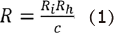
Hertz’s contact theory is also used to determine the dry contact mechanics of DM AHJ. This contact mechanic is achieved with the help of a ball-on-plane model with the same level of accuracy. The radius of equivalent ball, R, is determined from the inner liner and head radii, Ri and Rh, and the diametral clearance, c, as derived in equation 1[21]:
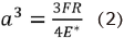
The interaction of a rigid indenter with a flat, large specimen is highly relevant in many situations. Hertz discovered that the radius of the contact, a, is linked to the indenter force F, the radius of the equivalent ball, R, and the elastic modulus of the materials by equation 2:
Which describes the most common case of contact between a rigid sphere and a flat surface. Where E* is the combined modulus of the inner liner and the head given by equation 3:
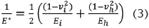
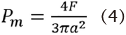
Ei and vi define the inner liner’s elastic modulus and Poisson’s ratio, whereas Eh and vh characterize the head’s elastic modulus and Poisson’s ratio, respectively. The maximum contact pressure, Pm, is calculated by dividing the indenter load by the predicted contact area and serves as a helpful normalizing parameter with real-world relevance. The maximum contact pressure formula is shown in equation 4:
Valid data can only be obtained from the simulation if the FE model has been verified. The simulation findings were checked by comparing them with the results found by Ruggiero and Silica[42]. The maximum contact pressure during typical walking cycles is compared in Figure 6 between the present simulation findings and the results of Ruggiero and Silica[42]. Ruggiero used a 28 mm head diameter, and the thickness of the liner was 9.5 mm. Therefore, the simulation in the current study also used a head diameter of 28 mm and the inner liner thickness of 9 mm and 10 mm for comparison.

The comparison graph demonstrates that the average difference between the current study (9 mm and 10 mm thickness) with those predicted by Ruggiero and Silica[42] is not significant, coming in at 4% and 2%, respectively that in acceptable range[27]. Variations in input quantities or parameter settings in the FEA program likely account for the discrepancy[43-45]. However, this is not an issue if the trend line agrees well with previous study as validation. Afterward, a complete simulation was run to determine the contact pressure and von Mises stress for two different head diameters (28 mm and 36 mm) and eight inner liner thicknesses (from 5 mm to 12 mm). The findings of contact pressure and von Mises stress for both head diameters and eight thicknesses of inner liner are discussed in the following subsection.
The initial output of the simulation was contact pressure. Contact pressure is the ratio between the typical load and the actual contact area, which is the total of the front and rear contact areas. There were contacts between two sets of surfaces. First, hard-on-soft contact[46] occurred at the head surface, paired with the inner liner’s concave surface. The second was hard-on-hard contact[47] between the acetabular cup’s concave surface and the outer liner’s convex surface.
Figure 7 depicts the maximum contact pressure on the inner liner, outer liner, and acetabular cup surfaces. The maximum contact pressure at a head diameter of 28 mm and 36 mm is shown in Figure 6, respectively. The highest load occurs when the gait cycle reaches 20%. At 28 mm head diameter, the maximum contact pressure is 13.5 MPa, on the inner liner thickness of 5 mm. While the head diameter is 36 mm, the maximum contact pressure is 10.4 MPa, on the inner liner thickness of 5 mm. There is a decrease in the highest contact pressure by 23%.

Then the lowest load occurs when the gait cycle is between 80%-90%. At 28 mm head diameter, the maximum contact pressure is 3.7 MPa, on the inner liner thickness of 12 mm. While the head diameter is 36 mm, the maximum contact pressure is 2.7 MPa, on the inner liner thickness of 8 mm. There is a decrease in the lowest contact pressure by 26%. The maximum contact pressure is lower with a head diameter of 36 mm than a head diameter of 28 mm. This finding demo
Figure 8 shows the percentage increase in contact pressure value on the outer liner and acetabular cup compared to the inner liner. The inner liner with a thickness of 12 mm has the smallest increase in contact pressure of the 28 mm head, which is 3% on the outer liner and 11% on the acetabular cup. It indicates that the contact pressure in the outer liner and acetabular cup is low and relatively just above the contact pressure in the inner liner. Additionally, with a head diameter of 36 mm, an increase in contact pressure of 7% on the outer liner and 8% on the acetabular cup takes place when the thickness is 8 mm. The lower the column, the better the thickness of the inner liner. The most proper inner liner thickness is depicted with the lowest column.

In SM AHJ, the ideal thickness of the inner liner is determined only by the liner. In distinction to SM AHJ, DM AHJ requires simultaneous and related consideration of contact pressure values on the inner liner, outer liner, and acetabular cup to determine the ideal thickness of the inner liner. Considering the proximity of the contact pressure values between the inner liner, outer liner, and acetabular cup, the suitable inner liner for a 28 mm head is 12 mm. In contrast, an 8-millimeter-thick inner liner is ideal for a 36-millimeter-diameter head. Figure 9 provides a visual representation of the results of the contact pressure distribution during gait cycles at 20% (maximum load) and at 80% (minimum load).

The second simulation outcome is von Mises stress. The von Mises stress is frequently employed to determine whether an isotropic and ductile metal will yield under complicated loading conditions[48]. In this DM AHJ, von Mises stress was measured on the inner liner, outer liner, and acetabular cup components. The inner liner was fabricated from UHMWPE, while the outer liner and acetabular cup were fabricated from 316L stainless steel. The maximal von Mises stresses on the inner liner, outer liner, and acetabular cup are shown in Figure 10. Figure 10A depicts the maximum von Mises stress at a head diameter of 28 mm, whereas Figure 10B depicts the maximum von Mises stress with a head diameter of 36 mm.

The outer liner has the highest von Mises value, in contrast to the contact pressure value found in the acetabular cup. The high von Mises is due to the outer liner being the thinnest DM AHJ component. Accordingly, descending von Mises values are as follows: outer liner, acetabular cup, and inner liner. At the same head diameter of 28 mm, the von Mises stress on the outer liner is about 79% more than on the inner liner. The incidence of von Mises in the acetabular cup rises by 19%. On the head with a 36 mm diameter, von Mises stress increases by 78% on the outer liner and 14% on the acetabular cup.
Regarding the outer liner and acetabular cup, the contact pressures occur on the convex and concave surfaces. The outer liner and acetabular cup trend lines are identical to the inner liner trend line, but the value is greater than that. Therefore, the sequence of the contact pressure values, going from the lowest to the highest, is as follows: Inner liner, outer liner, and acetabular cup.
The components of DM AHJ have well-defined maximum contact pressure values, and it is simple to determine such values. The maximum contact pressures in the outer liner at a head diameter of 28 mm and 36 mm are between the range of 4.5-16.3 MPa and 3.7-13.6 MPa, respectively. In contrast, the maximum contact pressures in the acetabular cup at a head diameter of 28 mm and 36 mm are between the range of 5.1-17.4 MPa and 4.3-14.6 MPa, respectively. In other words, the contact pressure is proportional to the applied load. When the load is increased, so is the contact pressure.
Several salient features characterize the contact issue in MoP prosthetic joints[49]. It should be noted that the metal component of a prosthetic joint has an elastic modulus that is 200 times or more than that of polyethylene. The elastic modulus of SS316L is 200000 MPa, whereas that of UHMWPE is just 1000 MPa. Therefore, the metal prosthetic component behaves identically to that of a rigid body, causing significant deformations in the polyethylene. The second characteristic is that the initial contact on the MoP is non-conformal due to a clearance between the head and the liner. The wider the clearance, the more non-conformal it will be[50]. Then once it is given a high load, the polyethylene will be severely deformed, while the head remains unaltered, resulting in conformal contact. The third key feature is that the polyethylene layer is restricted to a maximum thickness at a certain point.
These three characteristics render Hertzian theory inappropriate for problem-solving involving MoP prosthetic joints[51]. The reason is that the Hertzian theory is used when the deformation occurs on both contact surfaces. However, in MoP AHJ, the deformation takes place solely on the surface of the UHMWPE. The Hertzian theory is based on the non-conformal surface hypothesis. Nevertheless, if the polyethylene is substantially deformed, the Hertzian concept is no longer applicable since the contact has become conformal. The Hertzian theory is more appropriate for MoM AHJ[50]. Another issue is that the Hertzian theory only applies to thicknesses of a semi-infinite range; it cannot be used for thicknesses of a limited range, such as the UHMWPE layer on AHJ[52].
This study’s predicted contact pressure is consistent with earlier FE studies. The maximum contact pressures in the inner liner (UHMWPE) at a head diameter of 28 mm and 36 mm are between 3.7-13.5 MPa and 2.7-10.4 MPa, respectively. Wang et al[53] suggested that the contact pressure on the inner cup surface varies from 3.2 to 11.5 MPa. According to Wu et al[54], the contact pressure is between 1.5 and 15 MPa. Hua et al[55] reported that the contact pressure varies between 4 and 11 MPa. According to other researchers, the contact pressure values range between 6 and 19 MPa[56-58].
Maximum contact pressure diminishes as the thickness of the inner liner increases. Keep in mind, however, that there is a maximum thickness for the inner liner since it will also affect the diameter of the acetabular cup, given the greatest diameter of the acetabular cup that the acetabulum socket can still tolerate. Dubin et al[26] reported the maximum cup diameter to be 74-80 mm, but Chan et al[59] reported the maximum acetabular cup diameter to be 58 mm. In their study, Hua et al[55] used 56 mm for the outer diameter of the acetabular shell. In this current research, the outside diameter of the acetabular cup is 58.4 mm for a 12 mm inner liner thickness and 28 mm head diameter. While the head is 36 mm with an inner liner thickness of 12 mm, the acetabular cup has an outer diameter of 66.4 mm. Therefore, the thickness of the inner liner in this investigation remains within the permissible dimensions.
The maximum von Mises of the inner liner, outer liner, and acetabular cup are 2.4–11.4 MPa, 15.7–44.3 MPa, and 3.7–12.6 MPa, respectively, for 28 mm head. Then the maximum von Mises stresses of the 36 mm head are 1.9-8.9 MPa for the inner liner, 9.9-32.8 MPa for the outer liner, and 2.6-9.9 MPa for the acetabular cup. It should be noted that UHMWPE has a range of yield strengths. According to Malito et al[60], the engineering yield stress in UHMWPE formulations varies from 21.7 to 26.2 MPa. UHMWPE has a tensile strength of 35 MPa[61]. The maximum von Mises of the inner liner is lower than the yield strength of UHMWPE.
The predicted stresses matched those found in the FE works of literature used in this investigation. According to the subject-specific hip model, Anderson et al[62] presented that the von Mises stresses are between 0 and 44 MPa. Harris et al[63] found that, for healthy volunteers, peak stress while walking is 7.5 MPa, which is within the expected range under physiological stresses. Ravera et al[64] demonstrated that the von Mises stress varies between 0 and 12 MPa. According to Wu et al[54], the acetabular cartilage undergoes peak von Mises stresses of 7.5 MPa for a normal hip, 14.9 MPa for a sphere-replaced hip, and 13.1 MPa for a rotating ellipsoid-replaced hip. Dalli et al[56] stated that the maximum von Mises is 13.5 MPa. All of the simulated results presented illustrates contact behavior in DM AHJ that would bring beneficial to choosing suitable geometry for implant patient.
It is possible to conclude that the inner liner’s maximum von-Mises and contact pressure values are much less than the UHMWPE material’s yield strength (21-27 MPa). As the inner liner’s thickness rises, maximum contact pressure decreases. The maximum contact pressure is lower, with a head diameter of 36 mm compared to a head diameter of 28 mm. As a result, contact pressure and von Mises stress reduce with an increasing head diameter and inner liner’s thickness. The results of this study indicate that for a head with a diameter of 28 mm, an inner liner thickness of 12 mm is optimal. As for the 36 mm diameter head, the appropriate inner liner thickness is 8 mm. In this investigation, regular cycles of normal walking were the only activity examined. A more reliable method of distinguishing between ideal and reality models may be incorporating activities with severe loading and boundary conditions. Another drawback is that static analysis was used instead of dynamic analysis. In contrast, a more noticeable impact may be predicted if the investigation is conducted dynamically with continuous loading and more realistic boundary conditions. Then, more studies are required for the various head diameter and research about the wear and lubrication of this DM AHJ component. The findings in the present computational simulation would become orthopedic surgeon referral for choosing suitable geometry of DM AHJ for their patient.
The authors gratefully thank the author's respective institution for their strong support in this study.
Provenance and peer review: Invited article; Externally peer reviewed.
Peer-review model: Single blind
Specialty type: Mathematical and computational biology
Country/Territory of origin: Indonesia
Peer-review report’s scientific quality classification
Grade A (Excellent): 0
Grade B (Very good): B
Grade C (Good): 0
Grade D (Fair): 0
Grade E (Poor): 0
P-Reviewer: Yan ZQ, China S-Editor: Liu JH L-Editor: A P-Editor: Zhao YQ
| 1. | Philippot R, Camilleri JP, Boyer B, Adam P, Farizon F. The use of a dual-articulation acetabular cup system to prevent dislocation after primary total hip arthroplasty: analysis of 384 cases at a mean follow-up of 15 years. Int Orthop. 2009;33:927-932. [RCA] [PubMed] [DOI] [Full Text] [Cited by in Crossref: 150] [Cited by in RCA: 166] [Article Influence: 9.8] [Reference Citation Analysis (0)] |
| 2. | Langlais FL, Ropars M, Gaucher F, Musset T, Chaix O. Dual mobility cemented cups have low dislocation rates in THA revisions. Clin Orthop Relat Res. 2008;466:389-395. [RCA] [PubMed] [DOI] [Full Text] [Cited by in Crossref: 155] [Cited by in RCA: 140] [Article Influence: 8.2] [Reference Citation Analysis (0)] |
| 3. | Guyen O, Chen QS, Bejui-Hugues J, Berry DJ, An KN. Unconstrained tripolar hip implants: effect on hip stability. Clin Orthop Relat Res. 2007;455:202-208. [RCA] [PubMed] [DOI] [Full Text] [Cited by in Crossref: 64] [Cited by in RCA: 69] [Article Influence: 3.8] [Reference Citation Analysis (0)] |
| 4. | Capello WN, D'Antonio JA, Ramakrishnan R, Naughton M. Continued improved wear with an annealed highly cross-linked polyethylene. Clin Orthop Relat Res. 2011;469:825-830. [RCA] [PubMed] [DOI] [Full Text] [Cited by in Crossref: 55] [Cited by in RCA: 57] [Article Influence: 4.1] [Reference Citation Analysis (0)] |
| 5. | Campbell DG, Field JR, Callary SA. Second-generation highly cross-linked X3™ polyethylene wear: a preliminary radiostereometric analysis study. Clin Orthop Relat Res. 2010;468:2704-2709. [RCA] [PubMed] [DOI] [Full Text] [Cited by in Crossref: 41] [Cited by in RCA: 41] [Article Influence: 2.7] [Reference Citation Analysis (0)] |
| 6. | Mall NA, Nunley RM, Zhu JJ, Maloney WJ, Barrack RL, Clohisy JC. The incidence of acetabular osteolysis in young patients with conventional versus highly crosslinked polyethylene. Clin Orthop Relat Res. 2011;469:372-381. [RCA] [PubMed] [DOI] [Full Text] [Cited by in Crossref: 77] [Cited by in RCA: 82] [Article Influence: 5.9] [Reference Citation Analysis (0)] |
| 7. | Manley MT, Sutton K. Bearings of the future for total hip arthroplasty. J Arthroplasty. 2008;23:47-50. [RCA] [PubMed] [DOI] [Full Text] [Cited by in Crossref: 49] [Cited by in RCA: 37] [Article Influence: 2.2] [Reference Citation Analysis (0)] |
| 8. | Jamari J, Anwar IB, Saputra E, van der Heide E. Range of Motion Simulation of Hip Joint Movement During Salat Activity. J Arthroplasty. 2017;32:2898-2904. [RCA] [PubMed] [DOI] [Full Text] [Cited by in Crossref: 6] [Cited by in RCA: 10] [Article Influence: 1.3] [Reference Citation Analysis (0)] |
| 9. | Saputra E, Anwar IB, Jamari J, van der Heide E. A Bipolar Artificial Hip Joint Design for Contact Impingement Reduction. AMR. 2015;1123:164-168. [DOI] [Full Text] |
| 10. | Saputra E, Anwar IB, Ismail R, Jamari J, van der Heide E. Study of Unipolar and Bipolar Hip Prostheses Using Finite Element Simulation: Contact Stress Analysis. KEM. 2017;739:96-102. [DOI] [Full Text] |
| 11. | Sugano N, Tsuda K, Miki H, Takao M, Suzuki N, Nakamura N. Dynamic measurements of hip movement in deep bending activities after total hip arthroplasty using a 4-dimensional motion analysis system. J Arthroplasty. 2012;27:1562-1568. [RCA] [PubMed] [DOI] [Full Text] [Cited by in Crossref: 59] [Cited by in RCA: 57] [Article Influence: 4.4] [Reference Citation Analysis (0)] |
| 12. | Saputra E, Budiwan I, Ismail R, Jamari J, van der Heide E. Numerical simulation of artificical hip joint movement for western and japanse-style activities. Jurnal Teknologi. 2014;66:53-58. [DOI] [Full Text] |
| 13. | Yamamura M, Miki H, Nakamura N, Murai M, Yoshikawa H, Sugano N. Open-configuration MRI study of femoro-acetabular impingement. J Orthop Res. 2007;25:1582-1588. [RCA] [PubMed] [DOI] [Full Text] [Cited by in Crossref: 31] [Cited by in RCA: 28] [Article Influence: 1.6] [Reference Citation Analysis (0)] |
| 14. | Hemmerich A, Brown H, Smith S, Marthandam SS, Wyss UP. Hip, knee, and ankle kinematics of high range of motion activities of daily living. J Orthop Res. 2006;24:770-781. [RCA] [PubMed] [DOI] [Full Text] [Cited by in Crossref: 177] [Cited by in RCA: 182] [Article Influence: 9.6] [Reference Citation Analysis (0)] |
| 15. | Hidayat T, Jamari J, Bayuseno AP, Ismail R, Tauviqirrahman M, Wijaya PN. Study of Lubrication Fluid Pressure in Artificial Hip Joint During Bowing (Ruku’). In: Abdollah MF Bin, Amiruddin H, Phuman Singh AS, Abdul Munir F, Ibrahim A, editors. Proceedings of the 7th International Conference and Exhibition on Sustainable Energy and Advanced Materials (ICE-SEAM 2021), Melaka, Malaysia, Singapore: Springer Nature Singapore; 2022; 303–306. [DOI] [Full Text] |
| 16. | Muchammad M, Tauviqirrahman M, Ammarullah MI, Iqbal M, Setiyana B, Jamari J. Performance of textured dual mobility total hip prosthesis with a concave dimple during Muslim prayer movements. Sci Rep. 2024;14:916. [RCA] [PubMed] [DOI] [Full Text] [Cited by in RCA: 3] [Reference Citation Analysis (0)] |
| 17. | Tauviqirrahman M, Ammarullah MI, Jamari J, Saputra E, Winarni TI, Kurniawan FD, Shiddiq SA, van der Heide E. Analysis of contact pressure in a 3D model of dual-mobility hip joint prosthesis under a gait cycle. Sci Rep. 2023;13:3564. [RCA] [PubMed] [DOI] [Full Text] [Cited by in Crossref: 1] [Cited by in RCA: 23] [Article Influence: 11.5] [Reference Citation Analysis (0)] |
| 18. | Hidayat T, Ismail R, Tauviqirrahman M, Saputra E, Ammarullah MI, Lamura MDP, Bayuseno AP, Jamari. Running-in behavior of dual-mobility cup during the gait cycle: A finite element analysis. Proc Inst Mech Eng H. 2024;238:99-111. [RCA] [PubMed] [DOI] [Full Text] [Cited by in RCA: 3] [Reference Citation Analysis (0)] |
| 19. | Hidayat T, Jamari J, Bayuseno AP, Ismail R, Tauviqirrahman M, Saputra E. Short communication: Running-in behavior on single-mobility total hip arthroplasty. Med Eng Phys. 2022;104:103806. [RCA] [PubMed] [DOI] [Full Text] [Reference Citation Analysis (0)] |
| 20. | Mak MM, Jin ZM. Analysis of contact mechanics in ceramic-on-ceramic hip joint replacements. Proc Inst Mech Eng H. 2002;216:231-236. [RCA] [PubMed] [DOI] [Full Text] [Cited by in Crossref: 32] [Cited by in RCA: 32] [Article Influence: 1.4] [Reference Citation Analysis (0)] |
| 21. | Meng Q, Liu F, Fisher J, Jin Z. Contact mechanics and lubrication analyses of ceramic-on-metal total hip replacements. Tribol Int. 2013;63:51-60. [DOI] [Full Text] |
| 22. | Sariali E, Stewart T, Jin Z, Fisher J. Effect of cup abduction angle and head lateral microseparation on contact stresses in ceramic-on-ceramic total hip arthroplasty. J Biomech. 2012;45:390-393. [RCA] [PubMed] [DOI] [Full Text] [Cited by in Crossref: 26] [Cited by in RCA: 26] [Article Influence: 2.0] [Reference Citation Analysis (0)] |
| 23. | Walker PS, Gold BL. The tribology (friction, lubrication and wear) of all-metal artificial hip joints. 1971. Clin Orthop Relat Res. 1996;S4-10. [RCA] [PubMed] [DOI] [Full Text] [Cited by in Crossref: 11] [Cited by in RCA: 15] [Article Influence: 0.5] [Reference Citation Analysis (0)] |
| 24. | Corda JV, Chethan KN, Satish Shenoy B, Shetty S, Shyamasunder Bhat N, Zuber M. Fatigue life evaluation of different hip implant designs using finite element analysis. JAES. 2023;21:896-907. [DOI] [Full Text] |
| 25. | Hidayat T, Ammarullah MI, Saputra E, Lamura MDP, Chethan KN, Ismail R, Bayuseno AP, Jamari J. A method for estimating the contact area of a dual-mobility total hip prosthesis. AIP Advances. 2024;14:015317. [DOI] [Full Text] |
| 26. | Dubin JA, Westrich GH. Anatomic dual mobility compared to modular dual mobility in primary total hip arthroplasty: a matched cohort study. Arthroplast Today. 2019;5:509-514. [RCA] [PubMed] [DOI] [Full Text] [Full Text (PDF)] [Cited by in Crossref: 15] [Cited by in RCA: 26] [Article Influence: 4.3] [Reference Citation Analysis (0)] |
| 27. | Ammarullah MI, Hartono R, Supriyono T, Santoso G, Sugiharto S, Permana MS. Polycrystalline Diamond as a Potential Material for the Hard-on-Hard Bearing of Total Hip Prosthesis: Von Mises Stress Analysis. Biomedicines. 2023;11. [RCA] [PubMed] [DOI] [Full Text] [Cited by in Crossref: 111] [Cited by in RCA: 61] [Article Influence: 30.5] [Reference Citation Analysis (0)] |
| 28. | Saputra E, Anwar IB, Jamari J, Van Der Heide E. Finite element analysis of artificial hip joint movement during human activities. Procedia Eng. 2013;68:102-108. [DOI] [Full Text] |
| 29. | Gao Y, Zhao X, Zhang J, Jin Z. 3 - Explicit finite element modelling of artificial hip and knee joints. In: Jin Z, Li J, Chen ZBT-CM of B and B in the MS (Second E, editors. Woodhead Publ Ser Biomater, Woodhead Publishing, 2021; 13–39. [DOI] [Full Text] |
| 30. | Teoh SH, Chan WH, Thampuran R. An elasto-plastic finite element model for polyethylene wear in total hip arthroplasty. J Biomech. 2002;35:323-330. [RCA] [PubMed] [DOI] [Full Text] [Cited by in Crossref: 109] [Cited by in RCA: 60] [Article Influence: 2.6] [Reference Citation Analysis (0)] |
| 31. | Wegrzyn J, Antoniadis A, Sarshari E, Boubat M, Terrier A. Polyethylene wear of dual mobility cups: a comparative analysis based on patient-specific finite element modeling. Int Orthop. 2022;46:779-787. [RCA] [PubMed] [DOI] [Full Text] [Full Text (PDF)] [Cited by in Crossref: 2] [Cited by in RCA: 7] [Article Influence: 2.3] [Reference Citation Analysis (0)] |
| 32. | Ramos A, Simões JA. Tetrahedral versus hexahedral finite elements in numerical modelling of the proximal femur. Med Eng Phys. 2006;28:916-924. [RCA] [PubMed] [DOI] [Full Text] [Cited by in Crossref: 118] [Cited by in RCA: 88] [Article Influence: 4.6] [Reference Citation Analysis (0)] |
| 33. | Parrish M, Borden M, Staten M, Benzley S. A Selective Approach to Conformal Refinement of Unstructured Hexahedral Finite Element Meshes. In: Brewer ML, Marcum D, editors. Proceedings of the 16th International Meshing Roundtable, Berlin, Heidelberg: Springer Berlin Heidelberg, 2008; 251-68. [DOI] [Full Text] |
| 34. | Shankar S, Nithyaprakash R. Predicting the Wear of Soft-on-Hard Bearing Couples for Human Hip Prosthesis Using Finite Element Concepts. J Mech Med Biol. 2016;16:1-17. [RCA] [DOI] [Full Text] [Cited by in Crossref: 5] [Cited by in RCA: 5] [Article Influence: 0.6] [Reference Citation Analysis (0)] |
| 35. | Liu FX, He Y, Gao Z, Jiao D. Enhanced computational modelling of UHMWPE wear in total hip joint replacements: The role of frictional work and contact pressure. Wear. 2021:203985. [DOI] [Full Text] |
| 36. | Bevill SL, Bevill GR, Penmetsa JR, Petrella AJ, Rullkoetter PJ. Finite element simulation of early creep and wear in total hip arthroplasty. J Biomech. 2005;38:2365-2374. [RCA] [PubMed] [DOI] [Full Text] [Cited by in Crossref: 67] [Cited by in RCA: 44] [Article Influence: 2.1] [Reference Citation Analysis (0)] |
| 37. | Maxian TA, Brown TD, Pedersen DR, Callaghan JJ. Adaptive finite element modeling of long-term polyethylene wear in total hip arthroplasty. J Orthop Res. 1996;14:668-675. [RCA] [PubMed] [DOI] [Full Text] [Cited by in Crossref: 75] [Cited by in RCA: 57] [Article Influence: 2.0] [Reference Citation Analysis (0)] |
| 38. | Uddin MS. Contact of dual mobility implants: effects of cup wear and inclination. Comput Methods Biomech Biomed Engin. 2015;18:1611-1621. [RCA] [PubMed] [DOI] [Full Text] [Cited by in Crossref: 9] [Cited by in RCA: 12] [Article Influence: 1.1] [Reference Citation Analysis (0)] |
| 39. | Jamari J, Ammarullah MI, Santoso G, Sugiharto S, Supriyono T, Permana MS, Winarni TI, van der Heide E. Adopted walking condition for computational simulation approach on bearing of hip joint prosthesis: review over the past 30 years. Heliyon. 2022;8:e12050. [RCA] [PubMed] [DOI] [Full Text] [Cited by in Crossref: 72] [Cited by in RCA: 44] [Article Influence: 14.7] [Reference Citation Analysis (0)] |
| 40. | Ammarullah MI, Santoso G, Sugiharto S, Supriyono T, Wibowo DB, Kurdi O, Tauviqirrahman M, Jamari J. Minimizing Risk of Failure from Ceramic-on-Ceramic Total Hip Prosthesis by Selecting Ceramic Materials Based on Tresca Stress. Sustainability. 2022;14: 13413. [DOI] [Full Text] |
| 41. | Jamari J, Ammarullah MI, Saad APM, Syahrom A, Uddin M, van der Heide E, Basri H. The Effect of Bottom Profile Dimples on the Femoral Head on Wear in Metal-on-Metal Total Hip Arthroplasty. J Funct Biomater. 2021;12. [RCA] [PubMed] [DOI] [Full Text] [Full Text (PDF)] [Cited by in Crossref: 110] [Cited by in RCA: 86] [Article Influence: 21.5] [Reference Citation Analysis (0)] |
| 42. | Ruggiero, A. ; Sicilia, A. A Mixed Elasto-Hydrodynamic Lubrication Model for Wear Calculation in Artificial Hip Joints. Lubricants. 2020;8:72. [RCA] [DOI] [Full Text] [Cited by in Crossref: 10] [Cited by in RCA: 10] [Article Influence: 2.0] [Reference Citation Analysis (0)] |
| 43. | K N C, Bhat NS, Zuber M, Shenoy BS. Evolution of different designs and wear studies in total hip prosthesis using finite element analysis: A review. Cogent Eng. 2022;9:2027081. [DOI] [Full Text] |
| 44. | K N C, Zuber M, Bhat NS, Shenoy BS. Optimized trapezoidal-shaped hip implant for total hip arthroplasty using finite element analysis. Cogent Eng. 2020;7: 1719575. [DOI] [Full Text] |
| 45. | Bhawe AK, Shah KM, Somani S, Shenoy BS, Bhat NS, Zuber M, Chethan KN. Static structural analysis of the effect of change in femoral head sizes used in Total Hip Arthroplasty using finite element method. Cogent Eng. 2022;9:2027080. [DOI] [Full Text] |
| 46. | Chethan KN, Satish Shenoy B, Shyamasunder Bhat N. Role of different orthopedic biomaterials on wear of hip joint prosthesis: A review. Mater Today Proc. 2018;5:20827-36. [RCA] [DOI] [Full Text] [Cited by in Crossref: 8] [Cited by in RCA: 8] [Article Influence: 1.1] [Reference Citation Analysis (0)] |
| 47. | Kalayarasan M, Reginald J, Valerian Corda J, Dhanbal P, Jain PS, Keni LG, et al. Computational investigation of various stem designs with different radial clearances in total hip arthroplasty. Cogent Eng. 2023;10:2287296. [DOI] [Full Text] |
| 48. | K N C, Zuber M, Bhat N S, Shenoy B S, R Kini C. Static structural analysis of different stem designs used in total hip arthroplasty using finite element method. Heliyon. 2019;5:e01767. [RCA] [PubMed] [DOI] [Full Text] [Full Text (PDF)] [Cited by in Crossref: 37] [Cited by in RCA: 25] [Article Influence: 4.2] [Reference Citation Analysis (0)] |
| 49. | Bartel DL, Burstein AH, Toda MD, Edwards DL. The effect of conformity and plastic thickness on contact stresses in metal-backed plastic implants. J Biomech Eng. 1985;107:193-199. [RCA] [PubMed] [DOI] [Full Text] [Cited by in Crossref: 216] [Cited by in RCA: 150] [Article Influence: 3.8] [Reference Citation Analysis (0)] |
| 50. | Di Puccio F, Mattei L. Biotribology of artificial hip joints. World J Orthop. 2015;6:77-94. [RCA] [PubMed] [DOI] [Full Text] [Full Text (PDF)] [Cited by in CrossRef: 90] [Cited by in RCA: 45] [Article Influence: 4.5] [Reference Citation Analysis (2)] |
| 51. | Walker PS, Ben-Dov M, Askew MJ, Pugh J. The Deformation and Wear of Plastic Components in Artificial Knee Joints — An Experimental Study. Engineering in Medicine. 1981;10:33-38. [RCA] [DOI] [Full Text] [Cited by in Crossref: 33] [Cited by in RCA: 33] [Article Influence: 3.7] [Reference Citation Analysis (0)] |
| 52. | Bartel DL, Bicknell VL, Wright TM. The effect of conformity, thickness, and material on stresses in ultra-high molecular weight components for total joint replacement. JBJS - Series A. 1986;68:1041-1051. [RCA] [DOI] [Full Text] [Cited by in Crossref: 743] [Cited by in RCA: 556] [Article Influence: 14.3] [Reference Citation Analysis (0)] |
| 53. | Wang L, Yang W, Peng X, Li D, Dong S, Zhang S, Zhu J, Jin Z. Effect of progressive wear on the contact mechanics of hip replacements--does the realistic surface profile matter? J Biomech. 2015;48:1112-1118. [RCA] [PubMed] [DOI] [Full Text] [Cited by in Crossref: 8] [Cited by in RCA: 8] [Article Influence: 0.8] [Reference Citation Analysis (0)] |
| 54. | Wu HH, Wang D, Ma AB, Gu DY. Hip joint geometry effects on cartilage contact stresses during a gait cycle. Annu Int Conf IEEE Eng Med Biol Soc. 2016;2016:6038-6041. [RCA] [PubMed] [DOI] [Full Text] [Cited by in Crossref: 2] [Cited by in RCA: 2] [Article Influence: 0.3] [Reference Citation Analysis (0)] |
| 55. | Hua X, Li J, Jin Z, Fisher J. The contact mechanics and occurrence of edge loading in modular metal-on-polyethylene total hip replacement during daily activities. Med Eng Phys. 2016;38:518-525. [RCA] [PubMed] [DOI] [Full Text] [Cited by in Crossref: 32] [Cited by in RCA: 32] [Article Influence: 3.6] [Reference Citation Analysis (0)] |
| 56. | Dalli D, Buhagiar J, Mollicone P, Schembri Wismayer P. A novel hip joint prosthesis with uni-directional articulations for reduced wear. J Mech Behav Biomed Mater. 2022;127:105072. [RCA] [PubMed] [DOI] [Full Text] [Cited by in Crossref: 1] [Reference Citation Analysis (0)] |
| 57. | Ismail NF, Shuib S, Yahaya MA, Romli AZ, Shokri AA. Finite Element Analysis of Uncemented Total Hip Replacement: The Effect of Bone-Implant Interface. IJET. 2018;7:230-234. [DOI] [Full Text] |
| 58. | Affatato S, Merola M, Ruggiero A. Development of a Novel in Silico Model to Investigate the Influence of Radial Clearance on the Acetabular Cup Contact Pressure in Hip Implants. Materials (Basel). 2018;11. [RCA] [PubMed] [DOI] [Full Text] [Full Text (PDF)] [Cited by in Crossref: 13] [Cited by in RCA: 13] [Article Influence: 1.9] [Reference Citation Analysis (0)] |
| 59. | Chan PK, Cheung SL, Lam KH, Fung WC, Chan VWK, Cheung A, Cheung MH, Fu H, Yan CH, Chiu KY. Use of a modular hip dual-mobility articulation in patients with high risk of dislocation: a relatively small-sized acetabulum in Asian patients may limit its use. Arthroplasty. 2021;3:7. [RCA] [PubMed] [DOI] [Full Text] [Full Text (PDF)] [Cited by in RCA: 4] [Reference Citation Analysis (0)] |
| 60. | Malito LG, Arevalo S, Kozak A, Spiegelberg S, Bellare A, Pruitt L. Material properties of ultra-high molecular weight polyethylene: Comparison of tension, compression, nanomechanics and microstructure across clinical formulations. J Mech Behav Biomed Mater. 2018;83:9-19. [RCA] [PubMed] [DOI] [Full Text] [Cited by in Crossref: 20] [Cited by in RCA: 27] [Article Influence: 3.9] [Reference Citation Analysis (0)] |
| 61. | Affatato S, Ruggiero A, Merola M. Advanced biomaterials in hip joint arthroplasty. A review on polymer and ceramics composites as alternative bearings. Compos B Eng. 2015;83:276-283. [DOI] [Full Text] |
| 62. | Anderson AE, Ellis BJ, Maas SA, Weiss JA. Effects of idealized joint geometry on finite element predictions of cartilage contact stresses in the hip. J Biomech. 2010;43:1351-1357. [RCA] [PubMed] [DOI] [Full Text] [Full Text (PDF)] [Cited by in Crossref: 150] [Cited by in RCA: 123] [Article Influence: 8.2] [Reference Citation Analysis (0)] |
| 63. | Harris MD, Anderson AE, Henak CR, Ellis BJ, Peters CL, Weiss JA. Finite element prediction of cartilage contact stresses in normal human hips. J Orthop Res. 2012;30:1133-1139. [RCA] [PubMed] [DOI] [Full Text] [Cited by in Crossref: 146] [Cited by in RCA: 128] [Article Influence: 9.8] [Reference Citation Analysis (0)] |
| 64. | Ravera EP, Crespo MJ, Guarnieri FA, Braidot AA. Stress in Human Pelvis throughout the Gait Cycle: Development, Evaluation and Sensitivity Studies of a Finite Element Model. In: Braidot A, Hadad A, editors. VI Latin American Congress on Biomedical Engineering CLAIB 2014, Paraná, Argentina 29, 30 & 31 October 2014, Cham: Springer International Publishing, 2015; 246–249. [DOI] [Full Text] |