Copyright
©The Author(s) 2025.
World J Gastrointest Surg. Feb 27, 2025; 17(2): 94270
Published online Feb 27, 2025. doi: 10.4240/wjgs.v17.i2.94270
Published online Feb 27, 2025. doi: 10.4240/wjgs.v17.i2.94270
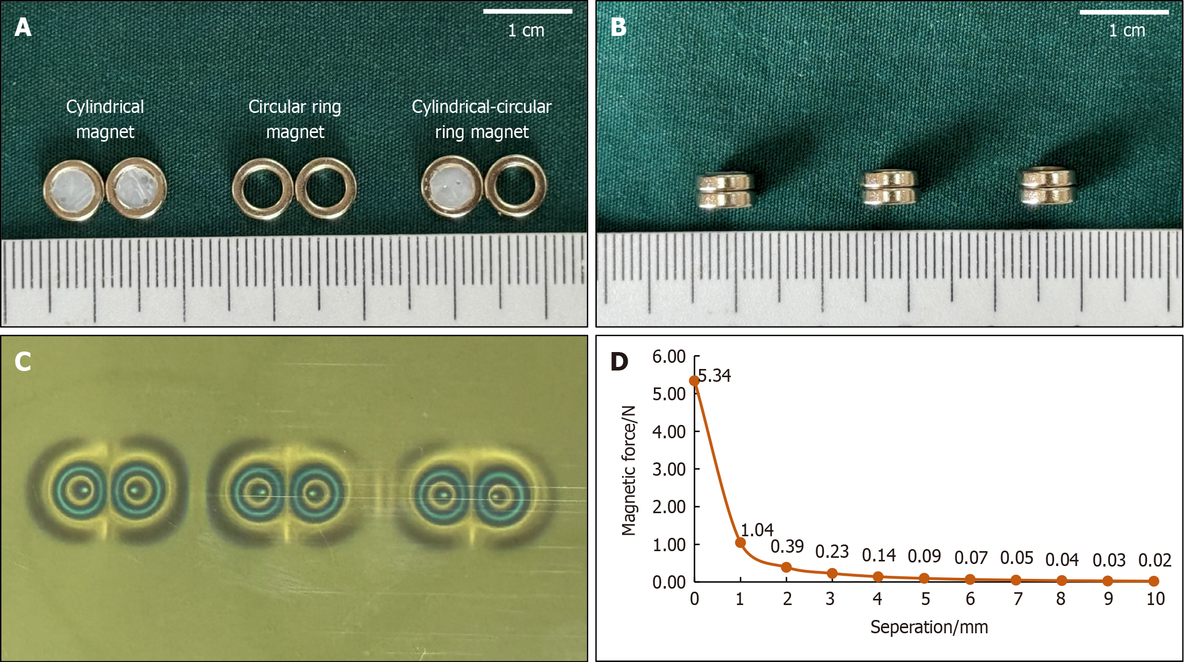
Figure 1 Magnets.
A: Front views of the cylindrical magnet and circular ring magnet; B: Side view of the magnets once attracted; C: Magnetic field viewing film showing the magnetic field distributions for the cylindrical magnets and circular ring magnets; D: The magnetic force curve.
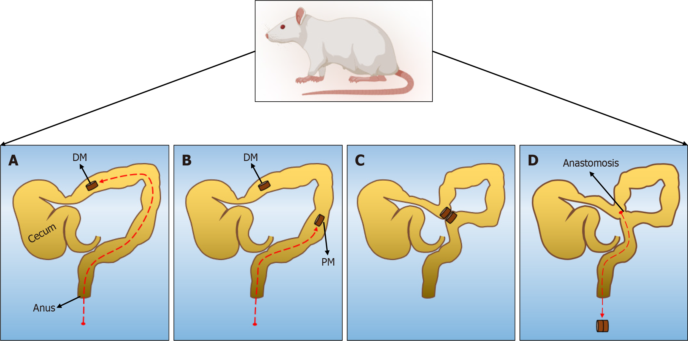
Figure 2 Schematic of the surgical procedure.
A: A magnet is inserted through the anus into the proximal portion of the colon; B: Another magnet is inserted through the anus to the distal end of the colon; C: The two magnets in the colon are attracted; D: The magnets are discharged after the side-to-side colonic anastomosis is established. DM: Daughter magnet; PM: Parent magnet.
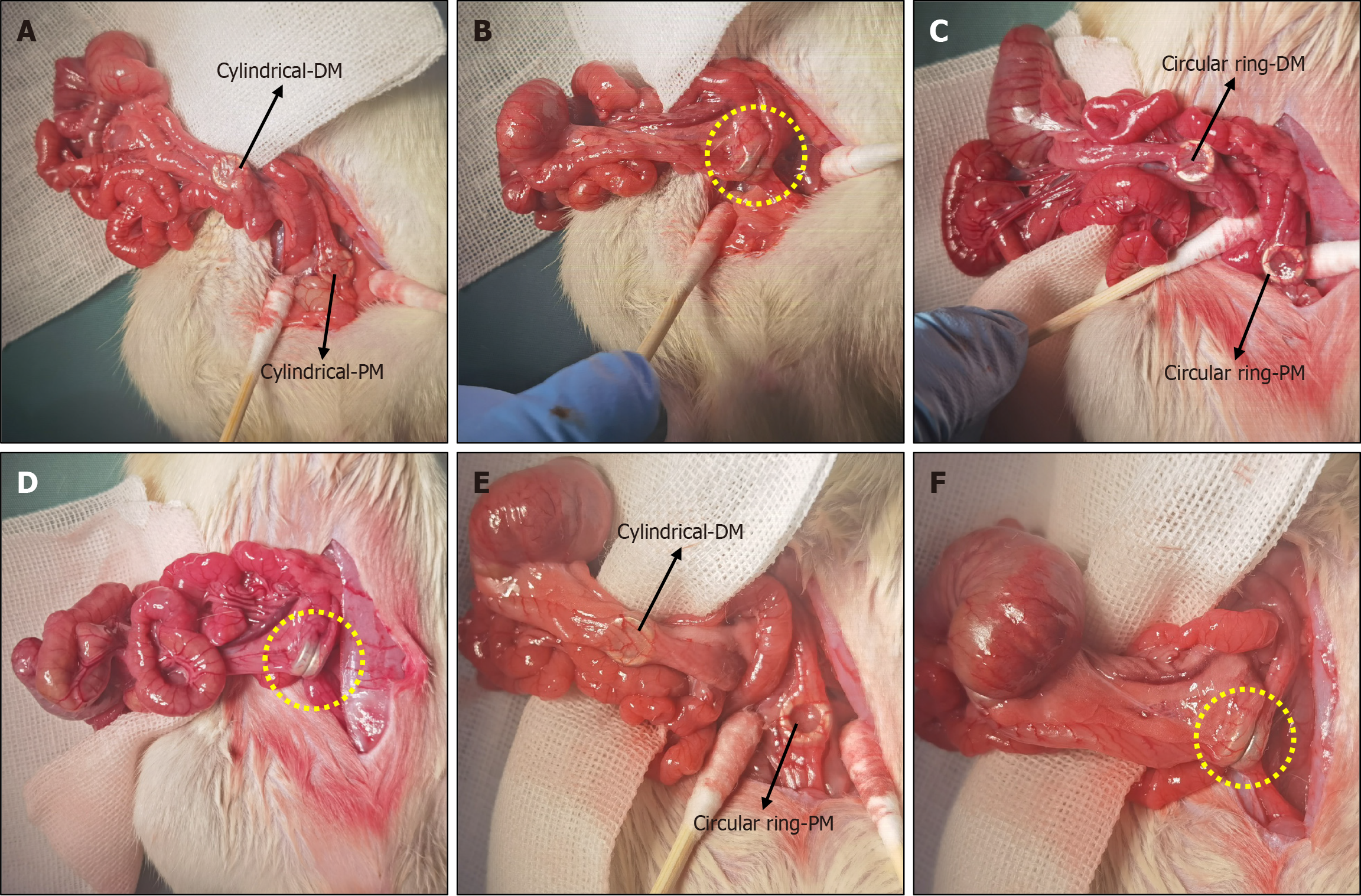
Figure 3 Surgical procedure.
A: For the cylindrical group, a cylindrical daughter magnet (DM) and cylindrical parent magnet (PM) were placed in the proximal and the distal end of the colon (black arrows); B: The two cylindrical magnets attracted together (yellow circle); C: For the circular group, a circular ring-DM and circular ring-PM were placed in the proximal and distal ends of the colon (black arrows); D: The two circular ring magnets attracted together (yellow circle); E: For the cylindrical–circular group, a cylindrical-DM and a circular ring-PM were placed in the proximal and distal ends of the colon, respectively (black arrows); F: The cylindrical-DM and circular ring-PM attracted together (yellow circle). DM: Daughter magnet; PM: Parent magnet.
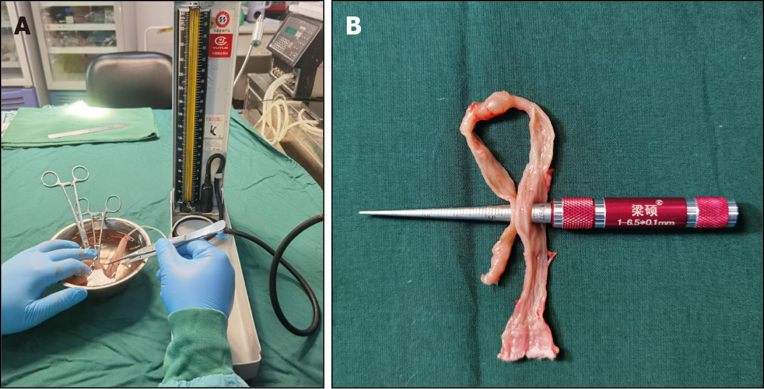
Figure 4 Measurement of anastomotic parameters.
A: Measurement of the burst pressure of the anastomosis; B: Measurement of the anastomotic diameter.
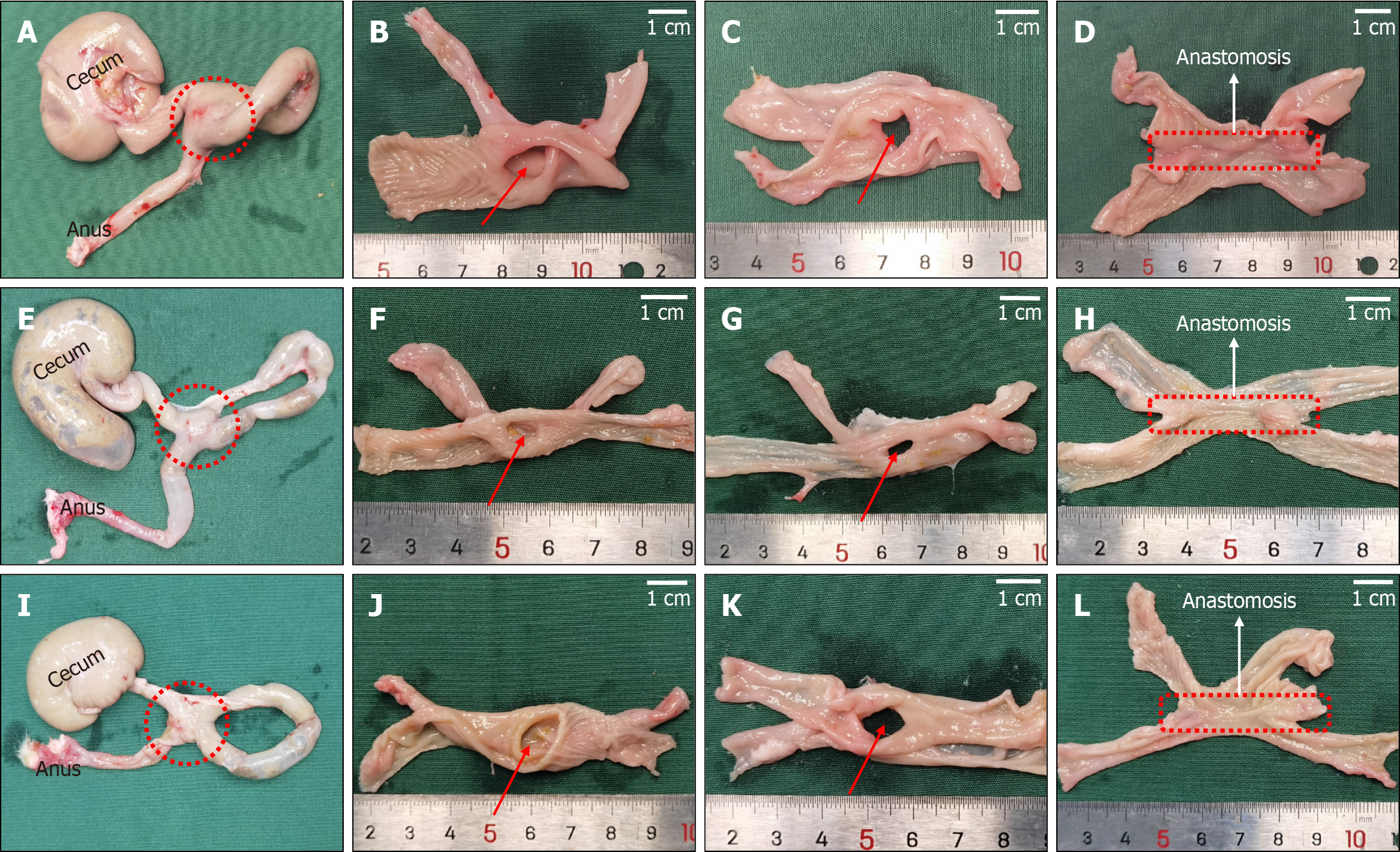
Figure 5 Anastomotic gross specimens.
A-D: Gross specimen of colon anastomosis from the cylindrical group; E-H: Gross specimen of colon anastomosis from the circular ring group; I-L: Gross specimen of colon anastomosis from the cylindrical–circular ring group.
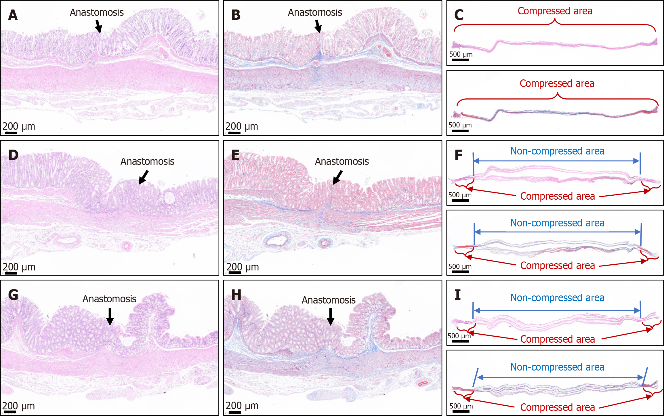
Figure 6 Representative images of histological staining of the colonic anastomosis.
A and B: Hematoxylin & eosin (H&E) and Masson trichrome staining of the anastomosis in the cylindrical group; C: H&E and Masson trichrome staining of the necrotic tissue between the daughter magnet (DM) and parent magnet (PM) in the cylindrical group; D and E: H&E and Masson trichrome staining of the anastomosis in the circular ring group; F: H&E and Masson trichrome staining of the necrotic tissue between the DM and PM in the circular ring group; G and H: H&E and Masson trichrome staining of the anastomosis in the cylindrical–circular ring group; I: H&E and Masson trichrome staining of the necrotic tissue between the DM and PM in the cylindrical–circular ring group.
Figure 7 Finite element simulation analysis.
A: Stress distribution after intestinal wall compression in the cylindrical group; B: Stress distribution after intestinal wall compression in the circular ring group; C: Stress distribution after intestinal wall compression in the cylindrical–circular ring group.
- Citation: Zhang MM, Shi AH, Muensterer OJ, Uygun I, Lyu Y, Yan XP. Comparative study of cylindrical vs circular ring magnets for colonic anastomosis in rats. World J Gastrointest Surg 2025; 17(2): 94270
- URL: https://www.wjgnet.com/1948-9366/full/v17/i2/94270.htm
- DOI: https://dx.doi.org/10.4240/wjgs.v17.i2.94270


