Published online Oct 25, 2015. doi: 10.4253/wjge.v7.i15.1170
Peer-review started: March 22, 2015
First decision: May 19, 2015
Revised: July 30, 2015
Accepted: August 16, 2015
Article in press: August 21, 2015
Published online: October 25, 2015
Processing time: 214 Days and 16.6 Hours
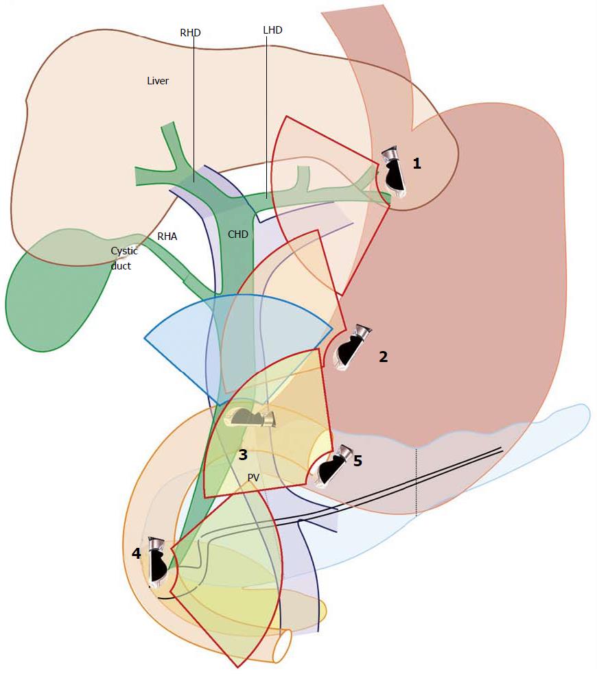
Imaging of common bile duct (CBD) can be done by many techniques. Endoscopic retrograde cholangiopancreaticography is considered the gold standard for imaging of CBD. A standard technique of imaging of CBD by endoscopic ultrasound (EUS) has not been specifically described. The available descriptions mention different stations of imaging from the stomach and duodenum. The CBD lies closest to duodenum and choice of imaging may be restricted to duodenum for many operators. Generally most operators prefer multi station imaging during EUS and the choice of selecting the initial station varies from operator to operator. Detailed evaluation of CBD is frequently the main focus of imaging during EUS and in such situations multi station imaging with a high-resolution ultrasound scanner may provide useful information. Examination of the CBD is one of the primary indications for doing an EUS and it can be done from five stations: (1) the fundus of stomach; (2) body of stomach; (3) duodenal bulb; (4) descending duodenum; and (5) antrum. Following down the upper 1/3rd of CBD can do imaging of entire CBD from the liver window and following up the lower 1/3rd of CBD can do imaging of entire CBD from the pancreatic window. This article aims at simplifying the techniques of imaging of CBD by linear EUS.
Core tip: Endoscopic ultrasound (EUS) is a new technology which has a steep learning curve. It is difficult to learn EUS as the standard techniques of EUS imaging have not been established. The common description of every organ or structure has been done by a station-wise imaging by most of the authors. The imaging of common bile duct (CBD) is an important part of EUS examination. The techniques of imaging of CBD by EUS have not been defined so far. This article aims at simplifying the techniques of imaging of CBD by linear EUS.
- Citation: Sharma M, Pathak A, Shoukat A, Rameshbabu CS, Ajmera A, Wani ZA, Rai P. Imaging of common bile duct by linear endoscopic ultrasound. World J Gastrointest Endosc 2015; 7(15): 1170-1180
- URL: https://www.wjgnet.com/1948-5190/full/v7/i15/1170.htm
- DOI: https://dx.doi.org/10.4253/wjge.v7.i15.1170
The common bile duct (CBD) can be imaged by many imaging modalities. Endoscopic ultrasound (EUS) is closest to endoscopic retrograde cholangio pancreaticography, which is the gold standard for imaging of CBD. A standard technique of imaging of CBD by EUS has not been specifically described and the available descriptions mention different stations of imaging from the stomach and duodenum[1-12]. Most operators prefer multi station imaging during EUS and the choice of selecting the initial station varies from operator to operator. The CBD lies closest to duodenum and choice of imaging may be restricted to duodenum for many operators where the imaging scanners do not allow deep image penetration. Detailed evaluation of CBD is frequently the main focus of imaging during EUS and in such situations multi station imaging with a high-resolution ultrasound scanner may provide useful information. In this article we review the techniques of linear imaging of CBD by EUS.
The right and left hepatic ducts unite in the hilar plate close to the right end of porta hepatis in front of right branch of portal vein to form the common hepatic duct (CHD). The cystic duct (length, 3-4 cm) runs postero inferiorly and to the left from the neck of gall bladder to join the right border of CHD at an acute angle. The CBD is 6.0 to 8.0 cm long and is generally divided into supraduodenal (upper 1/3rd), retroduodenal (middle 1/3rd), retropancreatic (lower 1/3rd) and intraduodenal segments. The supraduodenal CBD lies in the right border of lesser omentum (hepato-duodenal ligament) anterior to portal vein and to the left of hepatic artery proper[1]. The retroduodenal part passes behind the superior part of duodenum, to the right of gastroduodenal artery and in front of portal vein. The retropancreatic part runs behind the head of the pancreas to reach the medial border of second part of duodenum. In the retropancreatic course, CBD is intrapancreatic in 83% and retropancreatic in 17% cases[2]. The CBD and the main pancreatic duct (of Wirsung) unite to form the common channel (hepatopancreatic ampulla of Vater) which opens at the major duodenal papilla 8 cm distal to pylorus. The formation of a common channel occurs in 85% cases and in the rest 15% cases, the two ducts either open separately or form a V junction before opening.
All images in the present study have been generated from a detailed review of real-time recordings using the curved linear scanning echoendoscope EG-3830 UT (Pentax corporation, Tokyo, Japan), coupled with a Hitachi Avius and Hitachi 7500 processor (Hitachi Aloka Medical, Tokyo, Japan). Our image orientation is with the cranial aspect of the patient directed towards the right side of the screen. Four positions are commonly used during imaging from EUS: (1) the neutral position is where the front of the handle is facing the patient; (2) the open position to left is where the front of the handle is facing the patient’s feet. It is reached by turning anti clockwise through 90° from the neutral position; (3) the open position to right is the opposite of the open position to left. It is reached by turning clockwise through 90° from the neutral position; and (4) a further 90° rotation from open position to right can bring the handle in a position opposite to the neutral position.
EUS of the CBD can be done from five stations: (1) the fundus of stomach; (2) body of stomach; (3) duodenal bulb; (4) descending duodenum; and (5) antrum (Figure 1 and Table 1).
| Station | Home base structure | Main part of bile duct seen | Part of CBD seen on clockwise rotation1 | Part of CBD seen anti clockwise rotation2 |
| OG junction | l tributaries of LPV segment 2 and 3 | Segment 2 and 3 duct | Upper 1/3 | None |
| Body of stomach | Portal vein, splenic vein | Mid 1/3 | Lower 1/3 | Upper 1/3, left hepatic duct |
| Duodenal bulb | Portal vein | Mid 1/3 | Lower 1/3 | Upper 1/3 |
| Descending duodenum | SMV | Lower 1/3 | Mid 1/3, upper 1/3 | Intrapancreatic |
| Antrum | SMV | Lower 1/3 | Mid 1/3, upper 1/3 | None |
Rotation of the scope is the most important key to linear imaging of CBD. Rotation moves the imaging axis from one part of bile duct to other. Imaging with the scope in a straight position is helpful in transferring the effect of rotation of scope to the tip of ultrasound transducer. Most of the movements are done in a straight position of scope, except during imaging from station of duodenal bulb where the scope is placed in a J shaped position. Appropriate adjustments in right and left knobs along with in and out movement are also required to gain proper contact with the wall from all stations.
Manipulation around/ just beyond OG junction (40 cm) should be done under vision to avoid perforation. The imaging around/just beyond OG junction is best started from an open left position but can be also tried from an open right position.
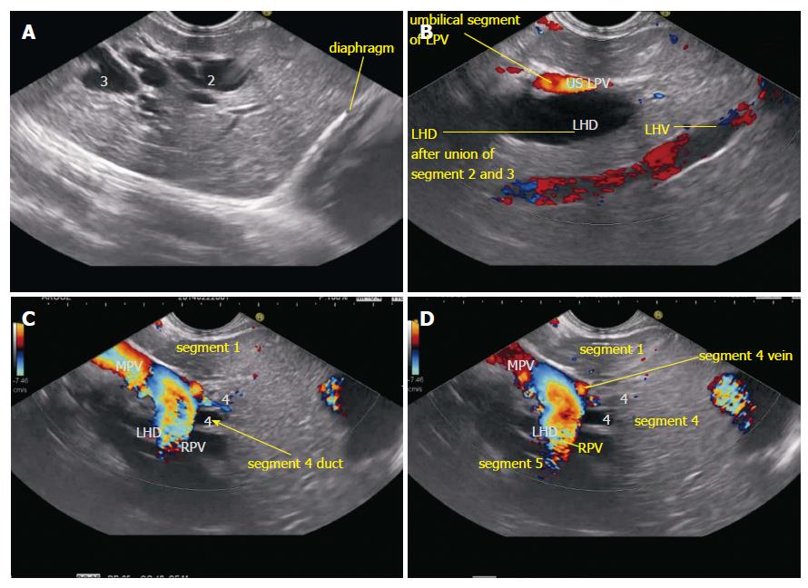
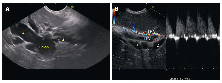
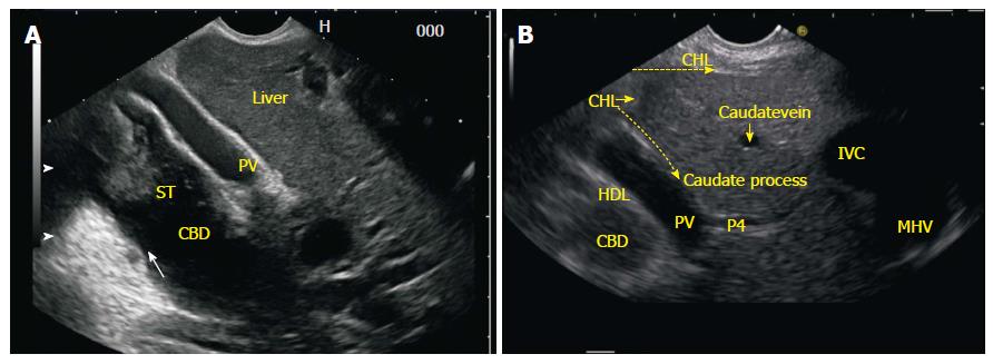
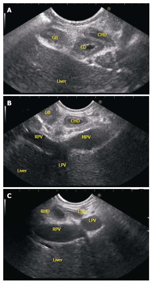
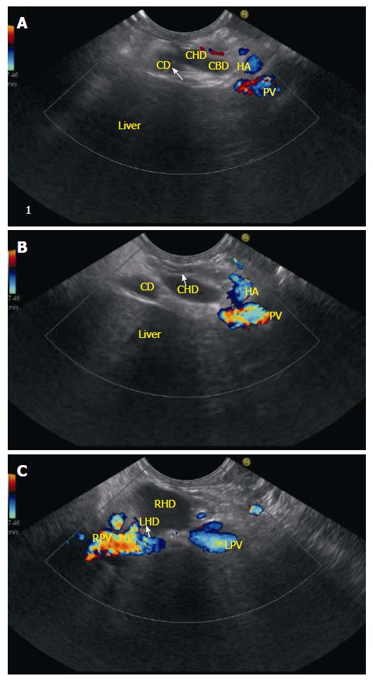
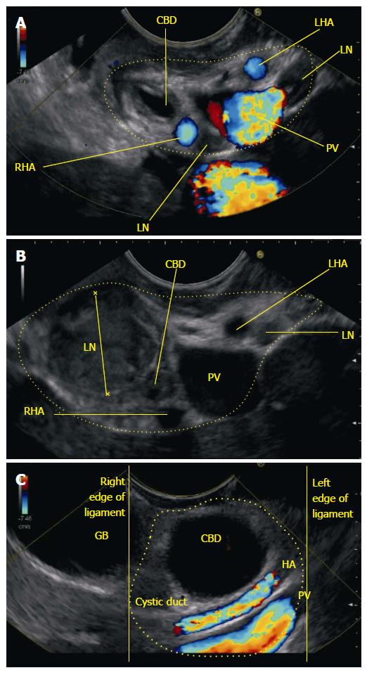
Imaging from open left position: Clockwise rotation from an open left position follows the left lobe segment 2 and 3 ducts to left hepatic duct and further rotation traces the left hepatic duct towards the liver hilum. If the intrahepatic biliary radicles (IHBR’s) are dilated it is easy to follow the course of ducts by clockwise rotation. If the IHBR’s are not dilated the segmental portal vein radicles should be followed. The gastrohepatic ligament (GHL), which come between the EUS probe and left lobe of liver, interferes with the imaging during rotation (Figure 2, Figure 3 and Figure 4).
Imaging from open right position: Generally imaging of right lobe of liver is not possible from OG junction, as the right lobe ducts generally lies farther away from the probe. However the GHL does not interfere in imaging of right hepatic duct and with suitable adjustments of focus and frequency the right lobe and ducts of segment 4/5 (if dilated) can be identified and followed towards the upper CBD near the hilum by anti-clockwise rotation.
Following down the upper 1/3rd of CBD can do imaging of entire CBD from the liver window and following up the lower 1/3rd of CBD can do imaging of entire CBD from the pancreatic window.
Following down from liver window: Imaging of CBD while following it down from the fundus towards body of stomach requires a movement of the EUS probe along lesser curvature. This movement can be easily executed under vision after distension of stomach with air but the presence of air usually creates interference with ultrasound imaging. To avoid this interference due to air, a smooth combination of three movements: (1) push in of about 25 to 30 cm. from fundus; (2) clockwise rotation of 90 degree; and (3) up movement of up and down knob for about 90 degree is generally preferred. This movement allows a relative blind slide of the transducer along lesser curvature with nil or minimum distension of air and follows down the CBD from upper 1/3rd towards the lower 1/3rd. Once the movement is completed the scope comes to lie in a position near the antrum and the left hand comes to lie close to the chest of the operator (Figure 5).
Following up from pancreatic window: A reversal of the movement described above can be done under vision by initially proceeding towards antrum after air inflation and subsequently coming back after air suction from antrum towards the fundus. This reversal movement follows up the CBD from the lower 1/3rd towards the upper 1/3rd. If it is difficult to trace the course of CBD by this movement, the home base of portal venous confluence of splenic vein with superior mesenteric vein is initially located in the neck of pancreas. The lower 1/3rd of CBD is easily identified behind the portal venous confluence (Figure 6).
The pylorus is located by “setting sun sign” and slight down angulation of tip may be required to get an end view of pylorus. Once the pylorus is seen the scope is pushed into 1st part of duodenum with slight upwards angulation and imaging from bulb is started after establishing contact with posterior duodenal wall. The contact with wall is generally established by turning in an anticlockwise (ACW) direction with down angulation of up and down knobs. Sometimes in this imaging the ACW rotation of the scope may take the scope down and below the level of table in a straight scope position. With suitable rotation and minor adjustments of knobs a home base position is identified where the portal vein is seen on the far side of the screen going from 5 o’clock position to 11 o’clock position. In this home base position the middle 1/3rd of CBD is commonly identified with slight adjustments of right and left knobs between the transducer and portal vein. Clockwise rotation from this position traces the lower 1/3rd of CBD and ACW rotation traces the upper 1/3rd of CBD as well as the cystic duct and gall bladder (Figure 7, Figure 8, Figure 9).
Imaging from duodenum requires two key movements. The first is entry into 2nd part of duodenum and the second is deep intubation into 3rd part of duodenum.
Passage into D2: Entry into D2 is facilitated by engagement of the tip of the probe at D1/D2 junction (superior duodenal angle). Four movements of knob at the superior duodenal angle, i.e., “right turn of knob, up turn of knob, clockwise rotation of the scope and pulling back of the scope” help in passage of probe into second part of duodenum. These movements bring the scope in a short position and place the tip of scope near the papilla once the scope is shortened to about 55 cm. Slow pulling back for shortening can be done by pulling the shaft of scope with the use of right hand or by the use of outward pressure on the shaft of scope by ulnar aspect of the left hand in an open right position. Endoscopic view should be always maintained during a combination of these movements while shortening to avoid a sudden jerk and entry of the transducer into 2nd part of duodenum.
Passage into D3: Once the second part of duodenum is entered two to three times pushing in and out is required to position the scope deeper into the third part of duodenum.
Imaging from duodenum: From the third part of duodenum a combination of three movements, i.e., slow withdrawal up to the first part of duodenum, clockwise and ACW torque and upward movement of the up and down knobs is required for getting good views of lower 1/3rd of bile duct. This combined movement traces the CBD from the lower 1/3rd towards the upper 1/3rd but as the scope comes towards the first part of duodenum it tends to slip back into stomach. Movement of the up knob in a fully up position and maintaining a clockwise stance during slow torque from the 2nd part of duodenum helps in preventing the scope from slipping back. Wedging the scope at D1/D2 junction with an inflated balloon is an alternative, which is preferred by some operators to prevent slipping back, but carries a small disadvantage of reverse intussusception of the 2nd part of duodenum into stomach.
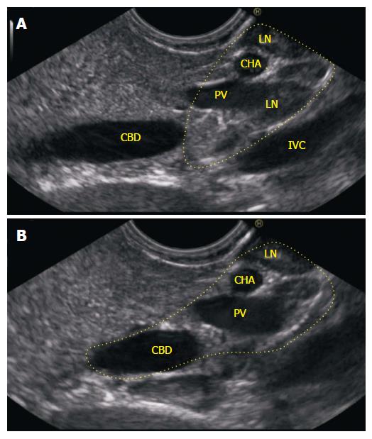
In a small number of cases it may be difficult to trace a normal CBD during this combined movement as most of the lumen of CBD gets compressed due to the pressure of transducer. In such cases the combined movement should be done with a main thrust on ACW rotation till it visualizes the anechoic bile duct within the bean shaped hepatoduodenal ligament. A clockwise rotation with slight push and relaxation of the pressure on up and down knob (reverse of the combined movement) now traces the CBD from the liver hilum towards the papilla.
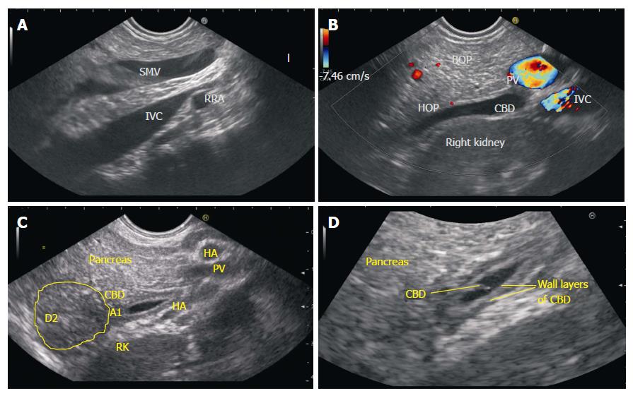
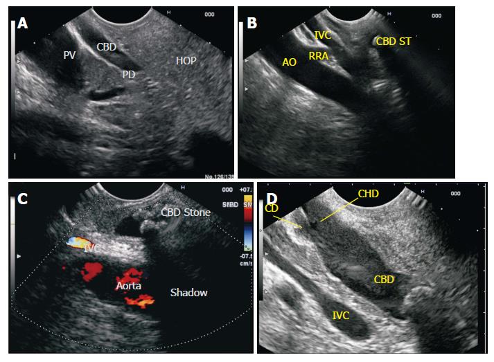
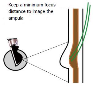
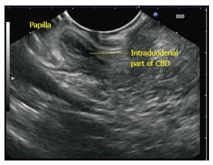
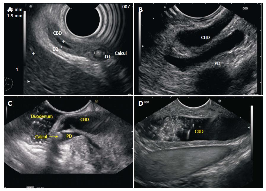
Imaging of CBD should be done from below the papilla from the third part of duodenum after instillation of water whenever pathology of papilla (stone or a periampullary tumor) causes distension of intraduodenal part of CBD. This technique provides adequate focal distance for imaging of papilla and good water coupling (Figure 10, Figure 11, Figure 12, Figure 13, Figure 14, Figure 15, Figure 16).
This imaging is similar to imaging through the pancreatic window from stomach as already described above. It can be done if evaluation of CBD is considered necessary once the scope slips back from the 2nd part of duodenum or once the examination from duodenum is completed. As the scope comes to lie opposite the head of pancreas the pancreatic window provides optimum imaging of lower 1/3rd of CBD (Figure 17).
The techniques described in the above section can be expected to reproduce the images as discussed in majority of cases and from most of the stations. The only station of CBD imaging which may not reproduce the images as described is from duodenal bulb. This difference in reproducing the images and a great variability of images comes mainly due to the variability of the position of scope (short loop, or J shaped position) and due to the use of balloon (nestled, wedged, withdrawn wedged, intussuscepted). The basic concept of imaging however remains simple: stomach shows mainly the upper 1/3rd of CBD, bulb shows mainly the middle 1/3rd of CBD and duodenum shows mainly the lower 1/3rd of CBD. The follow up imaging to trace entire CBD requires a clockwise rotation and push from upper 1/3rd of CBD. The follow up imaging to trace entire CBD requires an ACW rotation and pull from lower 1/3rd of CBD. The follow up imaging to trace entire CBD requires a clockwise rotation to trace the lower 1/3rd and an ACW rotation to trace the upper 1/3rd when imaging is started from middle 1/3rd of CBD.
P- Reviewer: Kurtoglu E, Skok P S- Editor: Ji FF L- Editor: A E- Editor: Jiao XK
| 1. | Dietrich CF. Endoscopic Ultrasound: An Introductory manual and Atlas. New York: Thieme 2006; . |
| 2. | Van Dam S, Sivak MV. Gastrointestinal Endosonography. Philadelphia, Pennsylvania: Saunders 1999; . |
| 3. | Rosch T, Will U, Chang KJ. Logitudianl Endosonography: Atlas and Manual for Use in the Upper Gastrointestinal Tract. Germany, 2001. . |
| 4. | Gress FG. Ishan Bhattacharya. Endoscopic Ultrasonography. Massachusetts: Wiley-Blackwell 2001; . |
| 5. | Hawes RH. Paul Fockens. Endosonographyh. Philadelphia: Saunders 2006; . |
| 6. | Rameshbabu CS, Wani ZA, Rai P, Abdulqader A, Garg S, Sharma M. Standard imaging techniques for assessment of portal venous system and its tributaries by linear endoscopic ultrasound: a pictorial essay. Endosc Ultrasound. 2013;2:16-34. [RCA] [PubMed] [DOI] [Full Text] [Cited by in Crossref: 3] [Cited by in RCA: 5] [Article Influence: 0.5] [Reference Citation Analysis (0)] |
| 7. | Sharma M, Rai P, Rameshbabu CS, Arya S. Techniques of imaging of pancreatic duct by linear endoscopic ultrasound. Endosc Ultrasound. 2014;3:179-190. [RCA] [PubMed] [DOI] [Full Text] [Full Text (PDF)] [Cited by in Crossref: 3] [Cited by in RCA: 7] [Article Influence: 0.6] [Reference Citation Analysis (0)] |
| 8. | Sharma M, Pathak A, Rameshbabu CS, Rai P, Kirnake V, Shoukat A, Dietrich F C, Sharma SS, Imaging of Pancreas Divisum by Linear Array Endoscopic Ultrasonography. Endosc Ultrasound. 2014;In press. |
| 9. | Sharma M, Rai P, Rameshbabu CS, Senadhipan B. Imaging of peritoneal ligaments by endoscopic ultrasound (with videos). Endosc Ultrasound. 2014;4:15-27. [RCA] [PubMed] [DOI] [Full Text] [Full Text (PDF)] [Cited by in Crossref: 8] [Cited by in RCA: 11] [Article Influence: 1.1] [Reference Citation Analysis (0)] |
| 10. | Sharma M, Rai P, Mehta V, Rameshbabu CS. Techniques of imaging of aorta and its 1st order branches by Endoscopic Ultrasound. Endosc Ultrasound. 2015;4:98-108. [RCA] [DOI] [Full Text] [Full Text (PDF)] [Cited by in Crossref: 4] [Cited by in RCA: 9] [Article Influence: 0.9] [Reference Citation Analysis (0)] |
| 11. | Sharma M, Rameshbabu CS, Dietrich F C, Rai P, Bansal R, Pathak A. Endoscopic Ultrasound of the hepatoduodenal ligament and porta hepatis. Endosc Ultrasound. 2014;In press. |
| 12. | Sharma M, Pathak A, Shoukat A, Thomas S N, Mehta D. Seagulls of EUS. Endosc Ultrasound. 2015;In Press. |


