Copyright
©The Author(s) 2020.
World J Gastroenterol. Mar 28, 2020; 26(12): 1340-1351
Published online Mar 28, 2020. doi: 10.3748/wjg.v26.i12.1340
Published online Mar 28, 2020. doi: 10.3748/wjg.v26.i12.1340
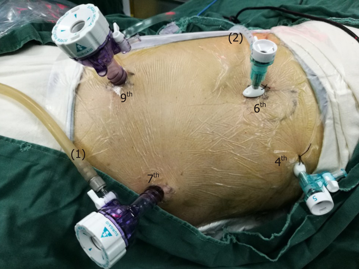
Figure 1 The position and operation ports of the patient during thoracic surgery.
The patient was placed in the semi-prone position. The camera port was placed at the 7th intercostal space (ICS) along the mid-axillary line. The other three ports were located at the 4th ICS along the anterior axillary line, the 6th ICS along the posterior axillary line, and the 9th ICS along the subscapular line. (1) Air intake duct of artificial pneumothorax; (2) Air outlet duct of artificial pneumothorax. ICS: Intercostal space.
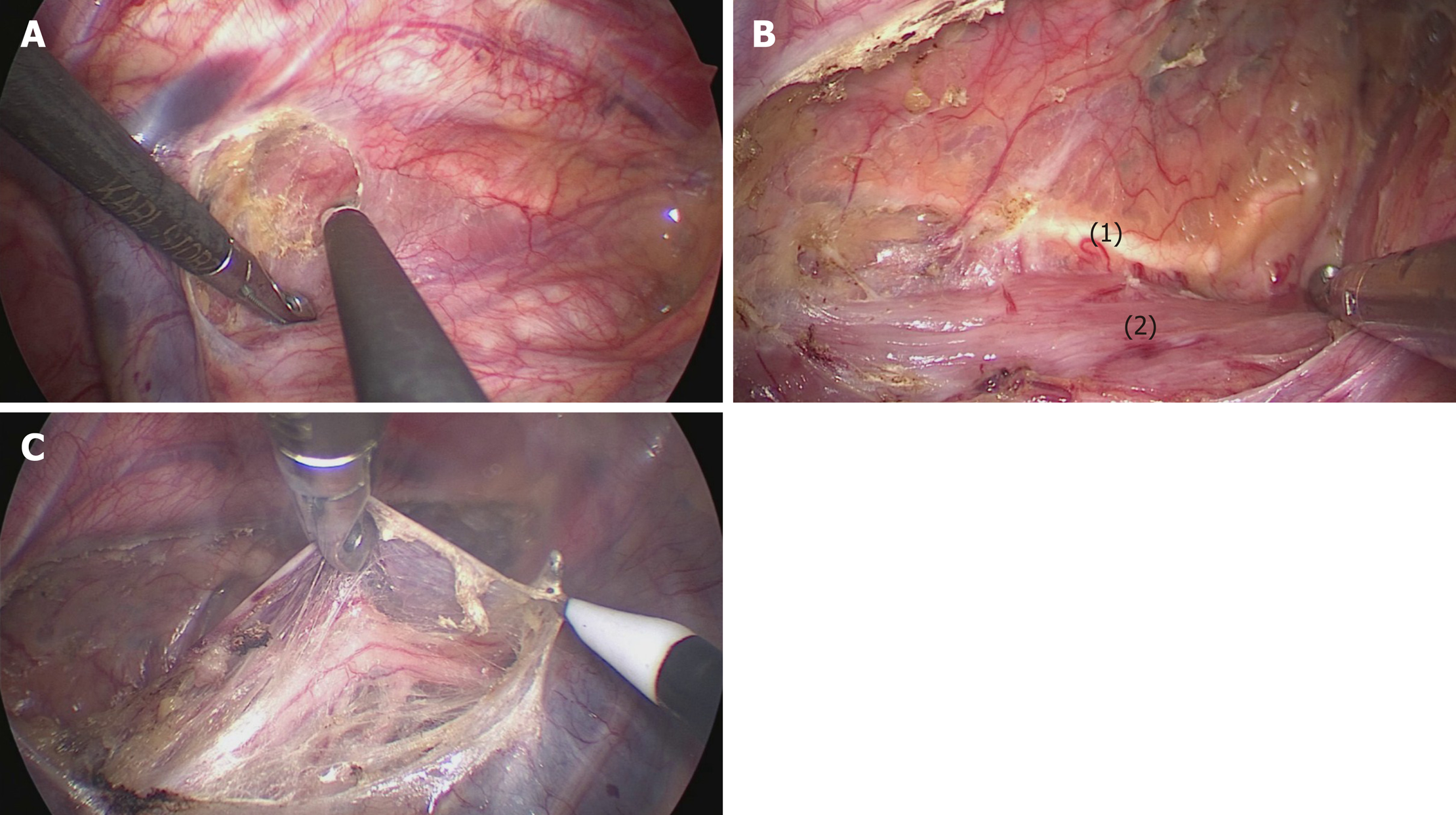
Figure 2 The mediastinal pleura was dissected on both sides.
A: The posterior mediastinal pleura above the arch of the azygos vein was dissected along the spine; B: The thoracic duct was fully exposed and carefully preserved, protecting the esophageal arteries on the dorsal side; C: The right vagus nerve was exposed by cutting the pleura toward the right subclavian artery. (1) Thoracic duct; (2) Esophagus.
Figure 3 Lymphadenectomy along the right RLN.
A: The right RLN was revealed at the level of the right subclavian artery. The hollow-out method was performed to identify the right RLN, LNs along the nerve, and the tracheoesophageal vessels; B: The right inferior thyroid artery was the landmark for the cranial boundary of lymphadenectomy along the right RLN. (1) Right RLN; (2) Right vagus nerve; (3-5) Esophageal branches of the right vagus nerve and RLN; (6) Mediastinal pleura; (7) Right subclavian artery; (8) Right inferior thyroid artery.
Figure 4 The middle and lower esophagus was mobilized from the posterior to anterior wall, until the bilateral crura of the diaphragm, pericardium, bilateral main bronchus, and carina were fully exposed.
During the procedure, the surrounding lymph nodes, mediastinal pleura and peri-esophageal tissues were dissected.
Figure 5 The upper thoracic esophagus was suspended to the dorsal side with a traction line.
Figure 6 Bi-directional exposure method.
When the upper esophagus was suspended with a traction line and drawn to the vertebral body, the trachea was pushed to the ventral side by an assistant. Meanwhile, the surgeon pushed the esophagus more delicately using grasping forceps to increase the working space in the upper mediastinum.
Figure 7 The bilateral pedicled nerve flap method.
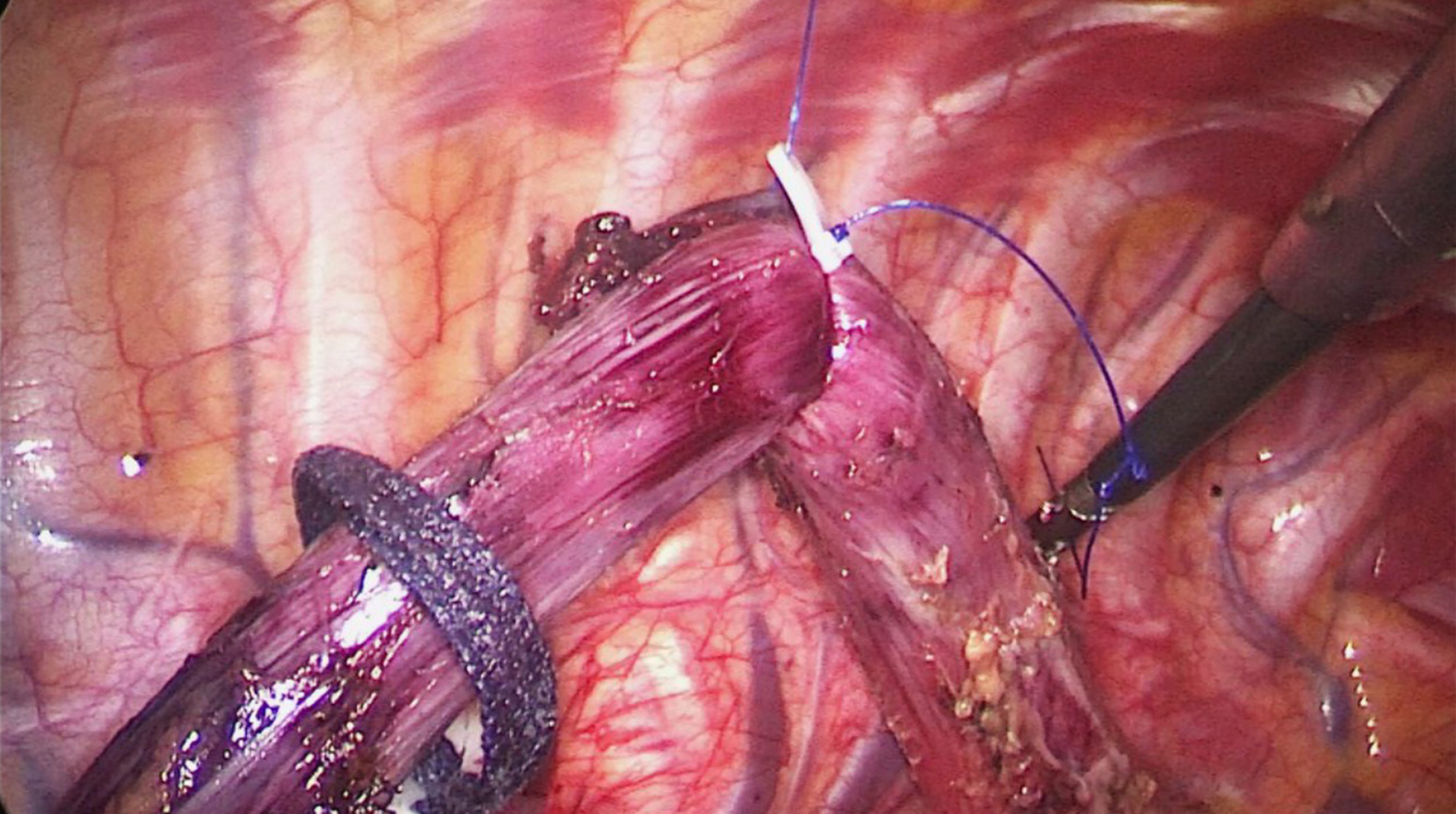
After the tissues were released from the edge of the trachea and left main bronchus, the anterior wall of the upper esophagus was completely mobilized from the trachea, with the left recurrent laryngeal nerve (RLN) and lymph nodes attaching to the upper esophagus. A: Then, a bilateral pedicled nerve flap, which was a two-dimensional membrane including the left RLN, peripheral LNs, and tracheoesophageal arteries, was exfoliated from the trachea; B: Subsequently, the “hollow-out” method was performed to transform the two-dimensional membrane into a three-dimensional structure, in which the left RLN, esophageal branches of the left RLN, lymph nodes and tracheoesophageal vessels could be easily identified. (1) Left RLN; (2) Lymph nodes along the left RLN; (3,4,7) Tracheoesophageal vessels; (5-6) Esophageal branches of the left RLN. RLN: Recurrent laryngeal nerve.
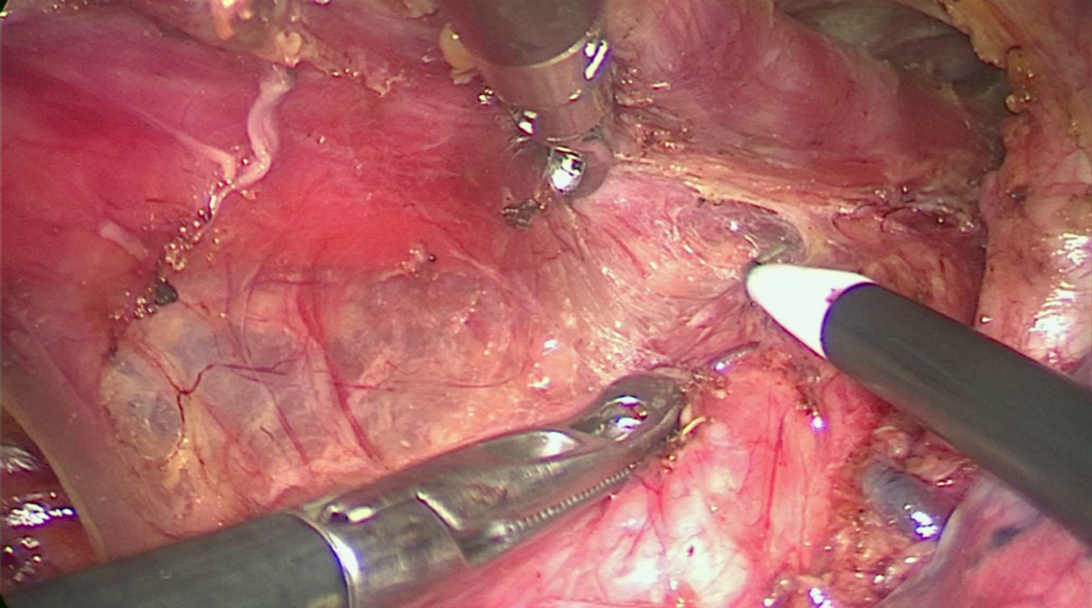
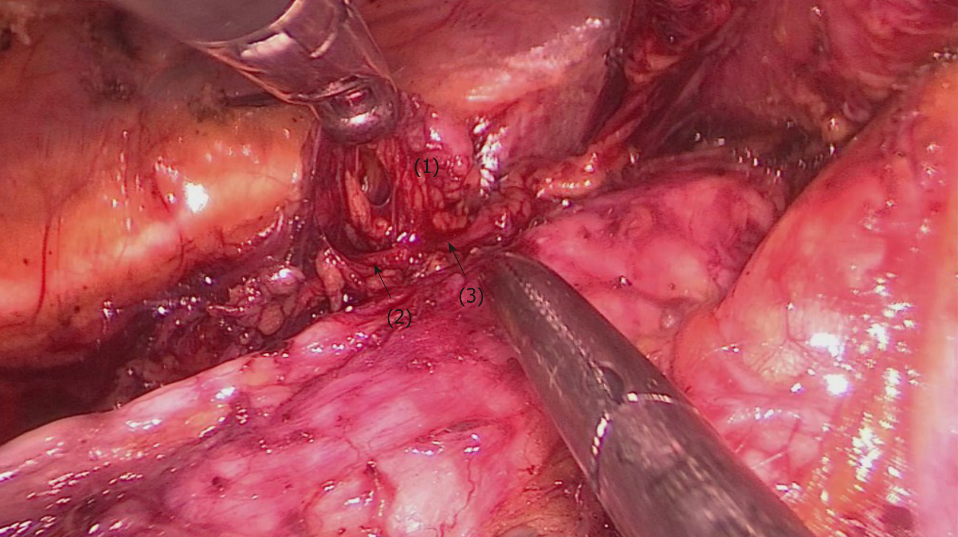
Figure 8 The upper esophagus was suspended with a traction line after dissociation from the trachea.
The left RLN and lymph nodes remained adjacent to the trachea in situ. Then, lymph nodes and peripheral tissues (marked 1) were held by the left hand of the surgeon to separate them from the left RLN (arrows 2-3).
- Citation: Chen WS, Zhu LH, Li WJ, Tu PJ, Huang JY, You PL, Pan XJ. Novel technique for lymphadenectomy along left recurrent laryngeal nerve during thoracoscopic esophagectomy. World J Gastroenterol 2020; 26(12): 1340-1351
- URL: https://www.wjgnet.com/1007-9327/full/v26/i12/1340.htm
- DOI: https://dx.doi.org/10.3748/wjg.v26.i12.1340


