Copyright
©The Author(s) 2017.
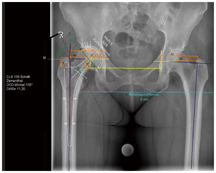
Figure 1 Digital planning of cup and stem for total hip arthroplasty of the right side (group 1).
A1: Hip offset: Perpendicular line from the teardrops through the centre of rotation to the femoral shaft axis, i.e., line B1 + C; A2: Contralateral hip offset; B1: Femoral offset: Perpendicular line from the centre of rotation to the axis of the femur; B2: Contralateral femoral offset; C: Horizontal position of the centre of rotation: Distance determined by the centre of rotation and one line perpendicular to the teardrops drawn through the centre of the teardrop; D: Vertical position of the centre of rotation: Line determined by the inter-teardrop line and the centre of rotation; E: Inclination angle: Angle determined by the inter-teardrop line and one axis extending through the cup opening; F: Stem orientation: Angle between femoral shaft axis and implant shaft axis; G: Implantation depth: Line between the upper edge of the prosthesis and the tip of the greater trochanter; H: Leg length difference: Quantified by subtracting the perpendicular distance from the biischial line to the proximal corner of the minor trochanters of both sides (measurements according to Bono, Dastane, Unnanuntana, Eggli[3,9-11]).
- Citation: Stigler SK, Müller FJ, Pfaud S, Zellner M, Füchtmeier B. Digital templating in total hip arthroplasty: Additional anteroposterior hip view increases the accuracy. World J Orthop 2017; 8(1): 30-35
- URL: https://www.wjgnet.com/2218-5836/full/v8/i1/30.htm
- DOI: https://dx.doi.org/10.5312/wjo.v8.i1.30


