Copyright
©The Author(s) 2015.
World J Transplant. Dec 24, 2015; 5(4): 145-153
Published online Dec 24, 2015. doi: 10.5500/wjt.v5.i4.145
Published online Dec 24, 2015. doi: 10.5500/wjt.v5.i4.145
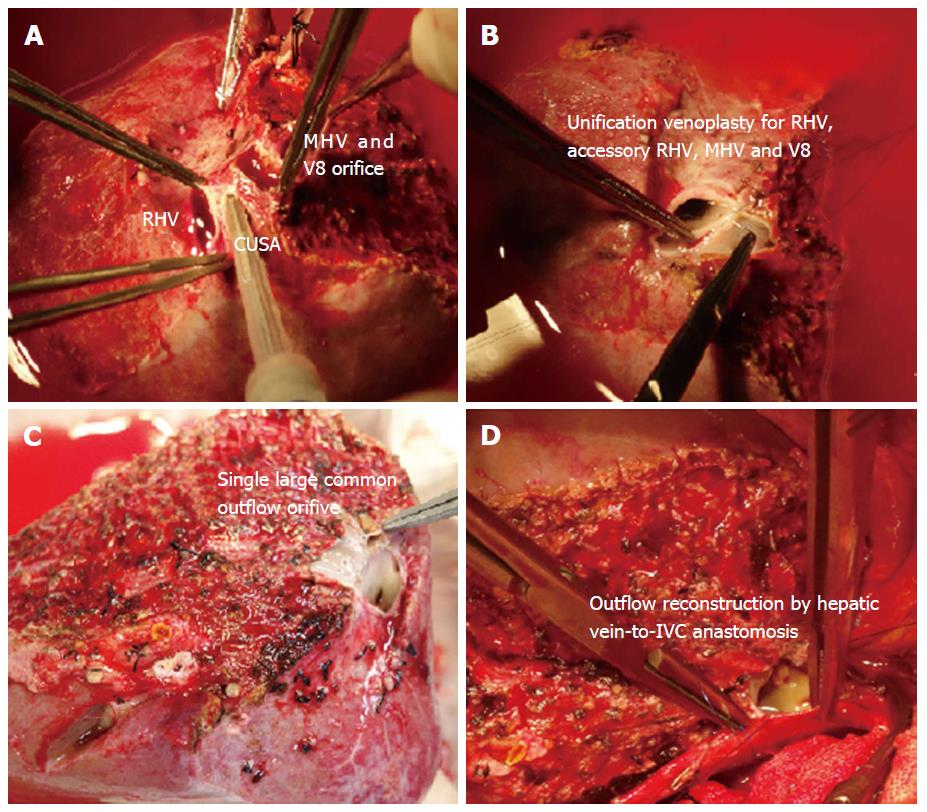
Figure 1 Methods of backtable venoplasty in right graft with the middle hepatic vein.
A: CUSA is used to dissect intervening parenchyma for a tension free venoplasty; B and C: Unification venoplasty of the adjacent walls; D: Outflow reconstruction requiring single anastomosis with the IVC. MHV: Middle hepatic vein; RHV: Right hepatic vein; CUSA: Cavitron ultrasonic surgical aspirator; IVC: Inferior vena cava; V8: Venous tributaries of segment 8.
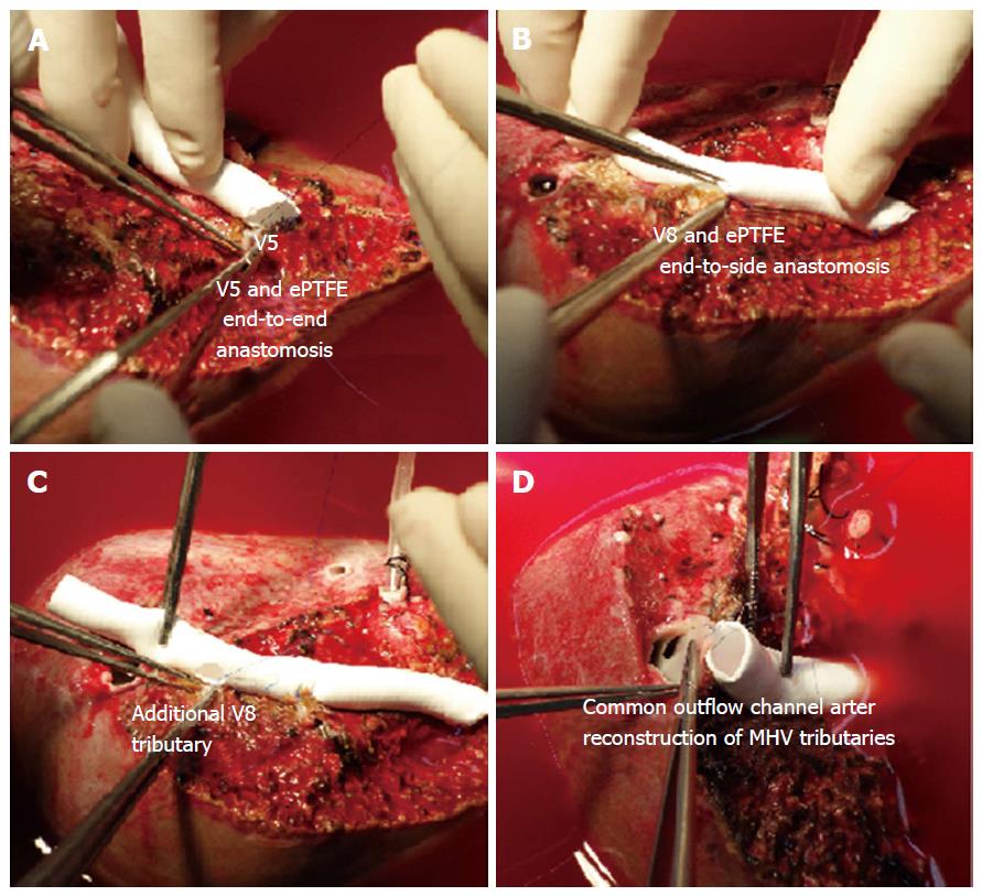
Figure 2 Technical details of the middle hepatic vein reconstruction using expanded polytetrafluoroethylene graft.
A: V5 branch is anastomosed with the ePTFE graft by an end-to-end anastomosis; B and C: V8 branches are anastomosed with the ePTFE graft by an end-to-side anastomosis; D: The other end of the graft is anastomosed with the anterior wall of the right hepatic vein to form a common outflow channel. ePTFE: Expanded polytetrafluoroethylene; MHV: Middle hepatic vein; V5: Venous tributaries of segment 5; V8: Venous tributaries of segment 8.
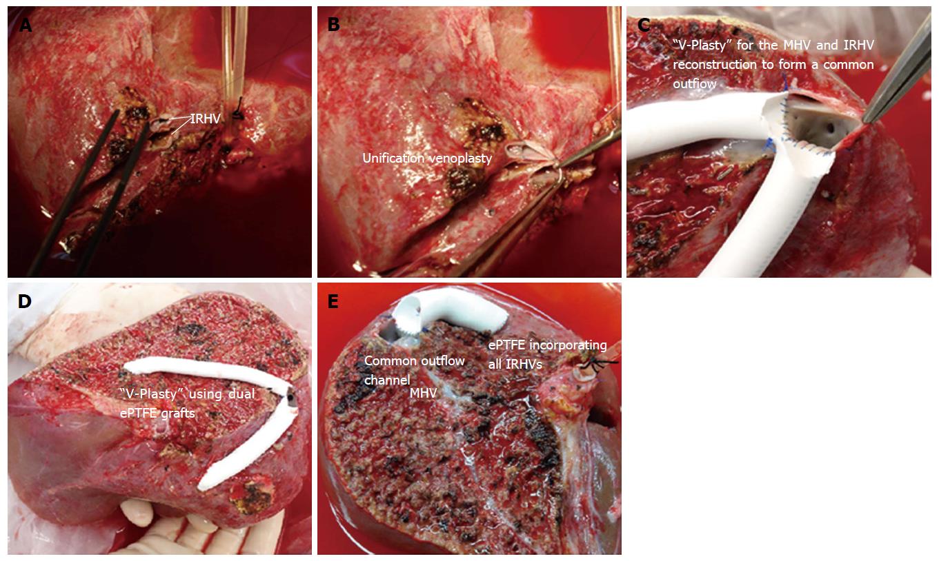
Figure 3 Reconstruction of the inferior right hepatic veins.
A and B: Unification venoplasty of the IRHVs; C and D: “V-Plasty” technique for the MHV and IRHV reconstruction; E: The IRHVs can be separately reconstructed using ePTFE vascular conduit for liver allograft with the MHV. IRHV: Inferior right hepatic vein; MHV: Middle hepatic vein; ePTFE: Expanded polytetrafluoroethylene.
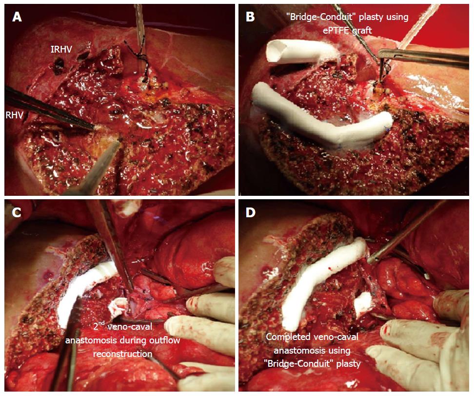
Figure 4 Bridging-Conduit venoplasty.
A: Liver allograft with the IRHVs located more caudal and ventral; B: Short ePTFE conduit is anastomosed with the IRHV in an end-to-end fashion; C and D: Second IVC anastomosis using bridging conduit venoplasty. RHV: Right hepatic vein; IRHV: Inferior right hepatic vein; ePTFE: Expanded polytetrafluoroethylene; IVC: Inferior vena cava.
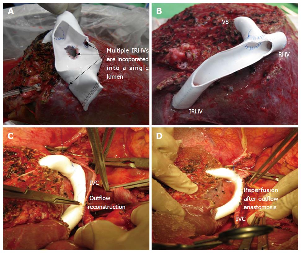
Figure 5 “Single-Oval Ostium” technique.
A: Right liver graft with multiple IRHVs draining randomly. V8 and IRHVs are incorporated in a single lumen using dual ePTFE grafts; B: Right liver allograft with the major IRHV located 10 cm from the RHV. Single wide outflow is reconstructed for the V8 and IRHV; C and D: Outflow reconstruction using Single-Oval Ostium technique. RHV: Right hepatic vein; IRHV: Inferior right hepatic vein; ePTFE: Expanded polytetrafluoroethylene; IVC: Inferior vena cava; V8: Venous tributaries of segment 8.
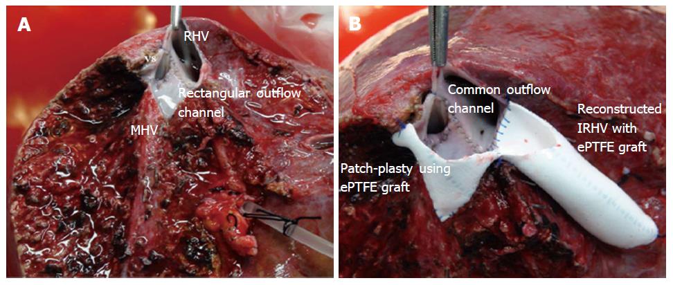
Figure 6 Patch-Venoplasty technique.
A: Right liver allograft with a wide-rectangular outflow orifice; B: Patch-Venoplasty using ePTFE graft. RHV: Right hepatic vein; IRHV: Inferior right hepatic vein; MHV: Middle hepatic vein; ePTFE: Expanded polytetrafluoroethylene.
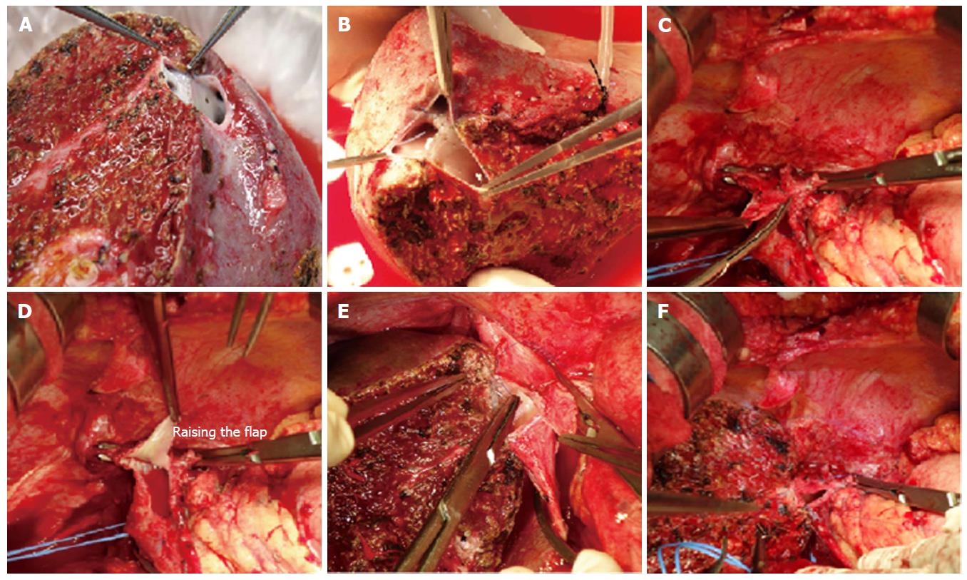
Figure 7 “Raising-Flap” technique in outflow reconstruction.
A and B: Right liver allografts with unduly large outflow; C-F: Steps of Raising flap technique during outflow reconstruction.
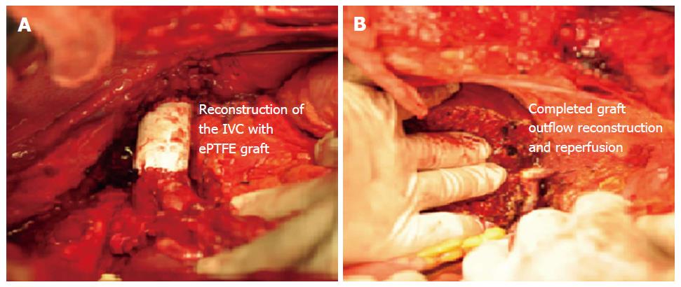
Figure 8 Retrohepatic inferior vena cava reconstruction.
A: Resection and reconstruction of the IVC with the ePTFE graft; B: Right liver allograft implantation with RHV to ePTFE (reconstructed IVC) anastomosis. IVC: Inferior vena cava; RHV: Right hepatic vein; ePTFE: Expanded polytetrafluoroethylene.
- Citation: Jeng LB, Thorat A, Yang HR, Li PC. Venous outflow reconstruction in living donor liver transplantation: Dealing with venous anomalies. World J Transplant 2015; 5(4): 145-153
- URL: https://www.wjgnet.com/2220-3230/full/v5/i4/145.htm
- DOI: https://dx.doi.org/10.5500/wjt.v5.i4.145


