Copyright
©The Author(s) 2025.
World J Transplant. Sep 18, 2025; 15(3): 104109
Published online Sep 18, 2025. doi: 10.5500/wjt.v15.i3.104109
Published online Sep 18, 2025. doi: 10.5500/wjt.v15.i3.104109
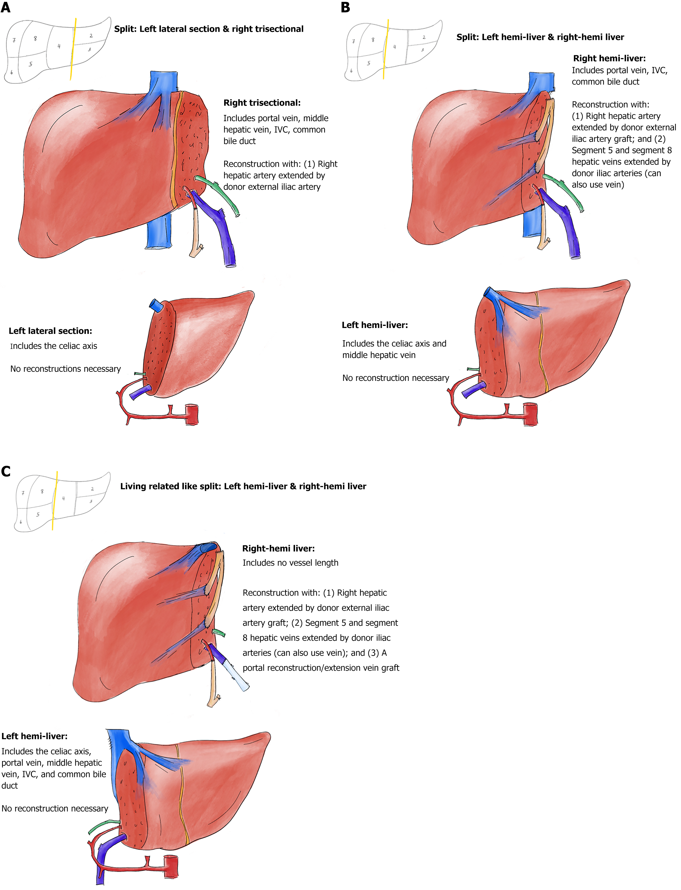
Figure 1 Deceased donor partial graft variants with vascular reconstructions.
A: Depiction of a left lateral–right trisectional graft split; B: Depiction of a left-right hemi-liver graft split, with the inferior vena cava (IVC) staying with the right hemi-liver graft; C: Depiction of a left-right hemi-liver graft split with the IVC staying with the left hemi-liver graft (living related donor like). All vascular inflow and outflow reconstructions in the depictions are performed before the connection to the normothermic machine perfusion pump, except the segments 5 and 8 hepatic veins outflow restorations in Figure 1C. Arteries are depicted in red; arterial grafts are depicted in orange; bile ducts are depicted in green; veins are depicted in dark blue; vein grafts are depicted in light blue.
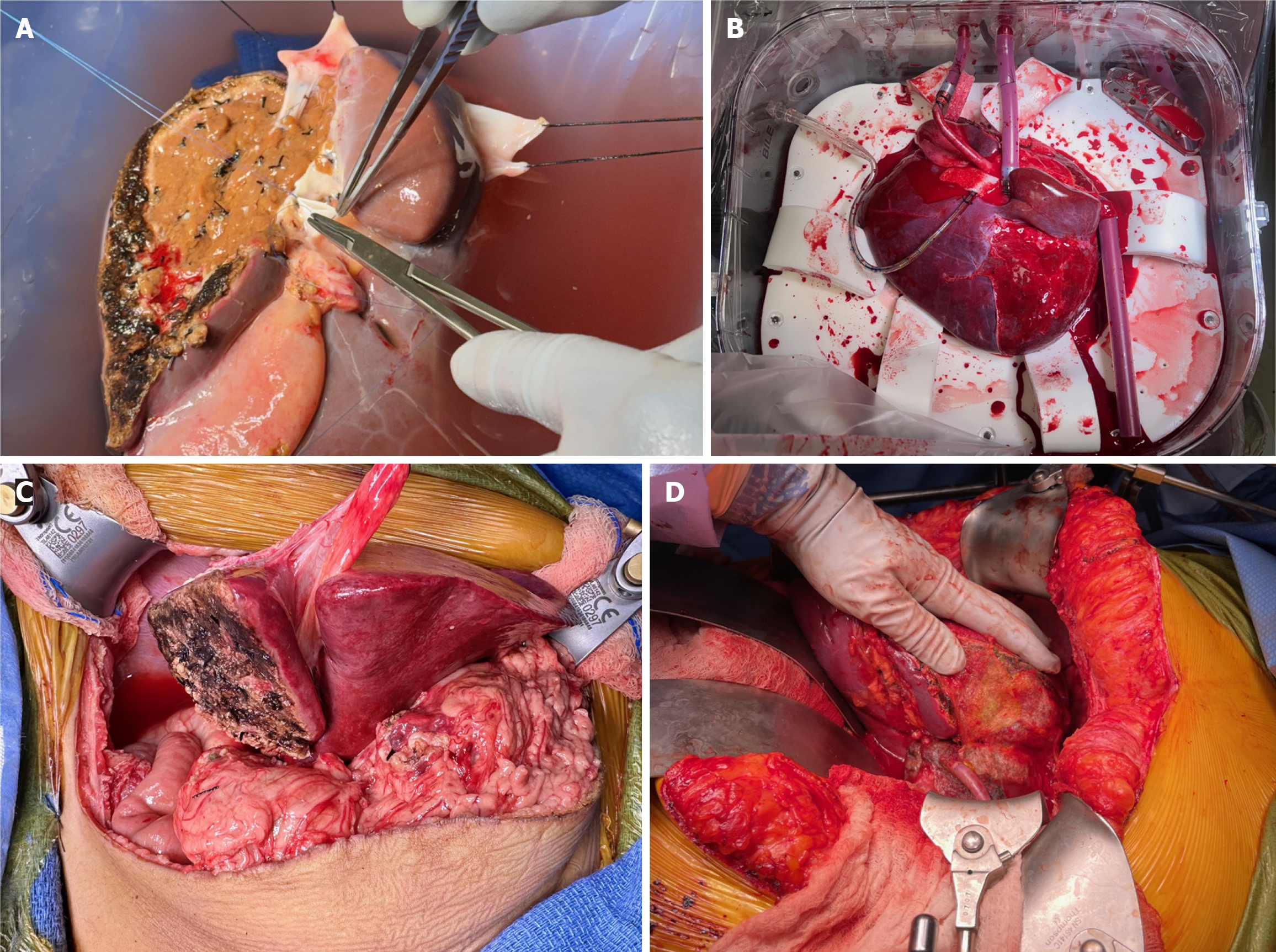
Figure 2 Right trisectional graft reconstructions and connection to normothermic machine perfusion pump.
A: Depiction of the donor iliac vein interposition graft reconstituting the proximal 4 cm of the middle hepatic vein (MHV) is depicted. Left portal vein ostium from main portal vein is being transversely closed. A donor iliac artery interposition graft to right hepatic artery (HA) will follow. Note at the transection surface that the amount of in-situ split was small (< 25%) to allow bloodless back table dissection and reconstruction of the MHV; B: It shows the placement of the right trisectional graft into the normothermic machine perfusion pump chamber with all the four canulae in their final positions. Note the graft rotan by 90 degrees clockwise to accommodate for the short portal vein. Note the 6 cm donor iliac artery interposition graft to right HA to allow connection to the 18 French arterial canula; C: The arterial inflow reconstruction; D: The arterial inflow reconstruction was performed with anastomosis of the right HA (extended by donor's right iliac artery) to the recipient’s common hepatic and gastroduodenal arteries confluence, creating a spatulated patch.
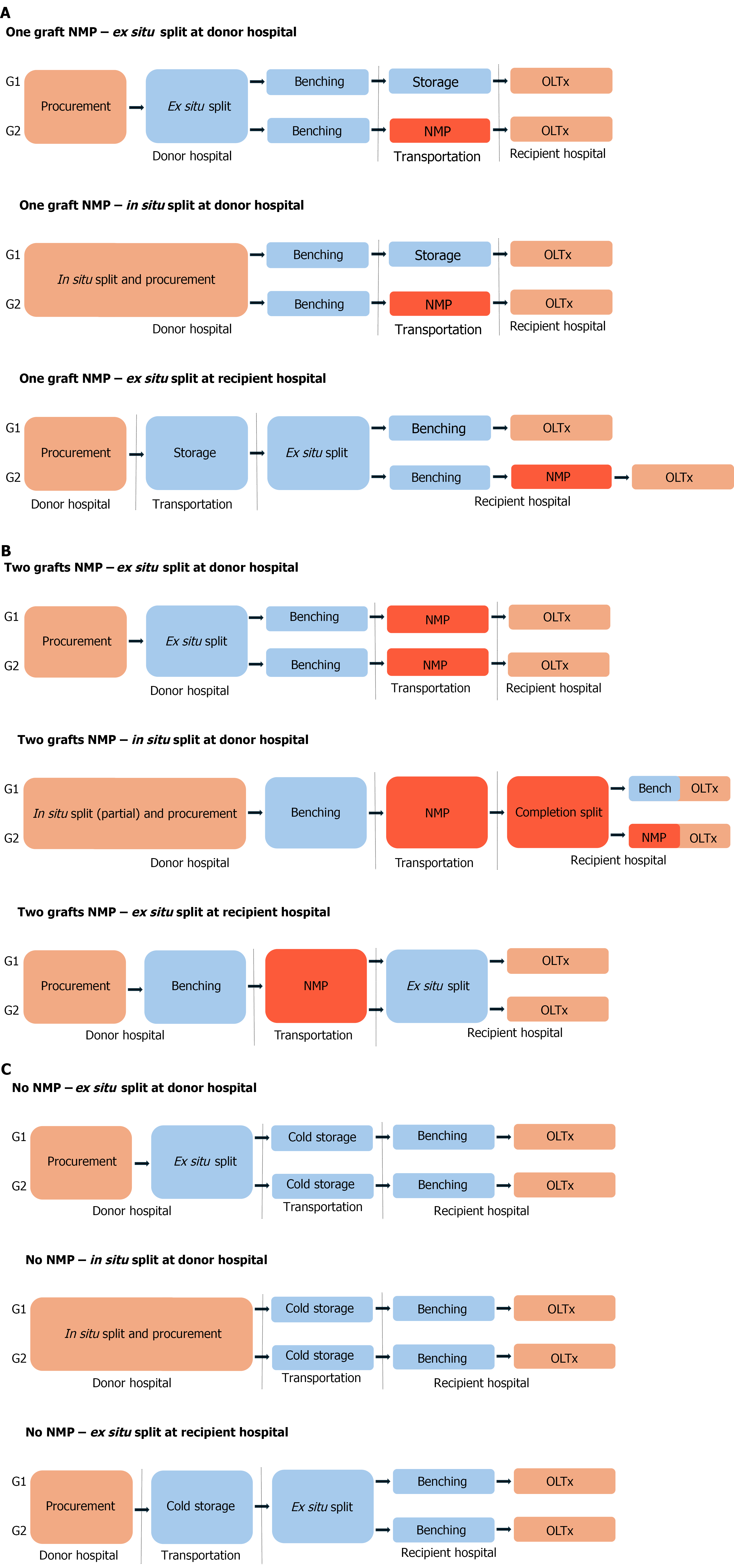
Figure 3 Sequence of the logistic steps for procurement and connection to normothermic machine perfusion pump of deceased donor partial grafts.
A: Logistic scenarios that lead to normothermic machine perfusion (NMP) of just one of the partial grafts; B: Logistic scenarios that lead to NMP of both partial grafts. In situ normothermia times are largely non-modifiable. Cold ischemia times should be kept minimal. Ex situ normothermia times are modifiable and can be extended ad lib to optimize logistics. Completion split in B2 scenario usually requires additional benching for at least one of the partial grafts; C: For comparison purposes, it describes current practices without NMP. In situ normothermia is depicted with orange. Standard cold storage conditions are depicted in blue. Ex situ normothermia is depicted in red. NMP: Normothermic machine perfusion; OLTx: Orthotopic liver transplantation.
- Citation: Baimas-George M, Archie WH, Soltys K, Soto JR, Levi D, Eskind L, Casingal V, Denny R, Attia M, Mazariegos GV, Vrochides D. Optimizing liver utilization for transplantation with partial grafts undergoing normothermic machine perfusion: Two case reports. World J Transplant 2025; 15(3): 104109
- URL: https://www.wjgnet.com/2220-3230/full/v15/i3/104109.htm
- DOI: https://dx.doi.org/10.5500/wjt.v15.i3.104109


