Copyright
©The Author(s) 2023.
World J Clin Urol. Aug 9, 2023; 12(2): 10-16
Published online Aug 9, 2023. doi: 10.5410/wjcu.v12.i2.10
Published online Aug 9, 2023. doi: 10.5410/wjcu.v12.i2.10
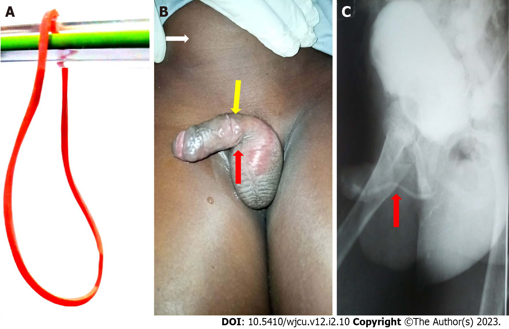
Figure 1 Initial patient presentation at the facility and follow-up contrast imaging.
A: Showing typical elastic rubber band; B: Physical examination findings showing the distended suprapubic region from urine retention (white arrow), circumferential penile shaft scar-site of rubber band application (yellow arrow), and ventral urethrocutaneous fistulous exit (red arrow); C: The combined retrograde urethrogram and voiding cystourethrogram showing the location of an evolving urethral stricture (red arrow).
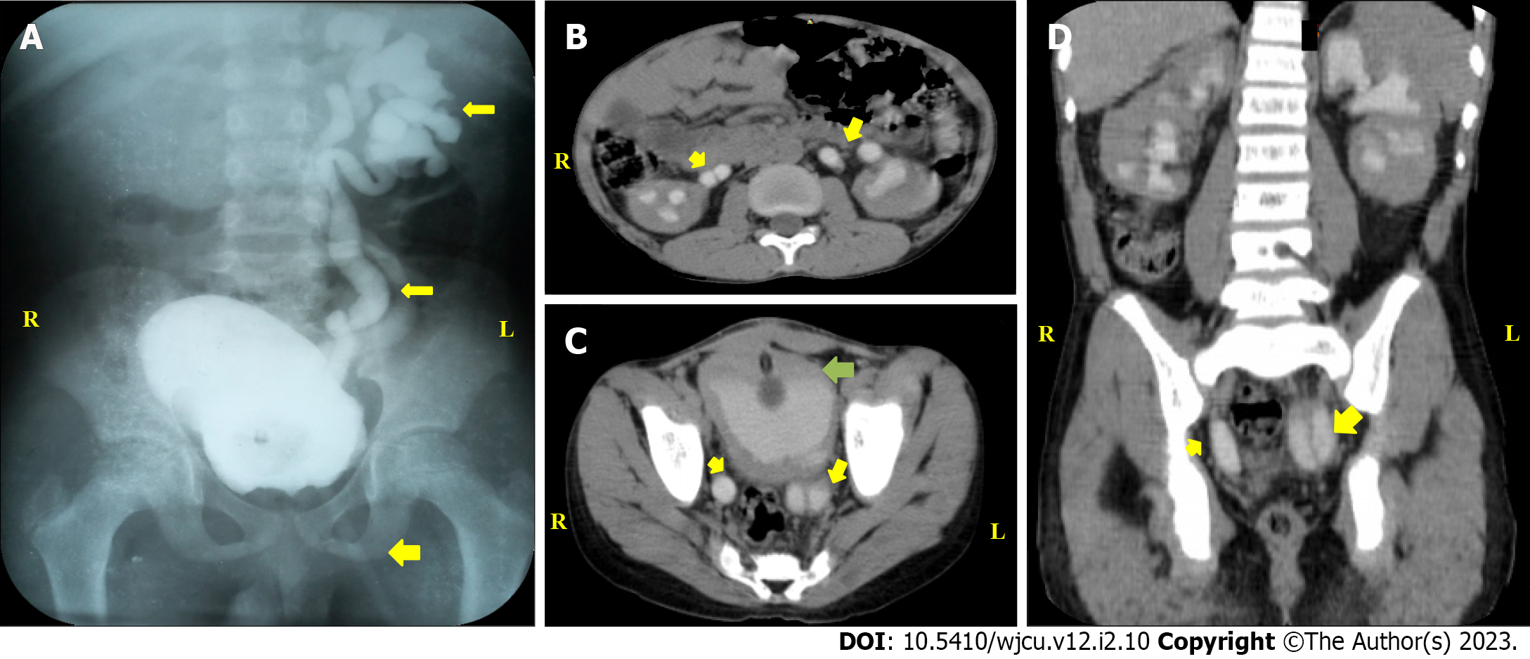
Figure 2 Contrast imaging studies.
A: Static cystogram showing duplex left collecting systems and ureters with reflux (yellow arrows) and suprapubic catheter (broader yellow arrow); B: Computerized tomography scan, axial view showing bilateral duplex upper ureters (yellow arrows); C: Computerized tomography scan, axial view demonstrating right partial duplex and left complete duplex lower ureters (yellow arrows), and bladder (green arrow); D: Computerized tomography scan, coronal view of the ureters (yellow arrows).
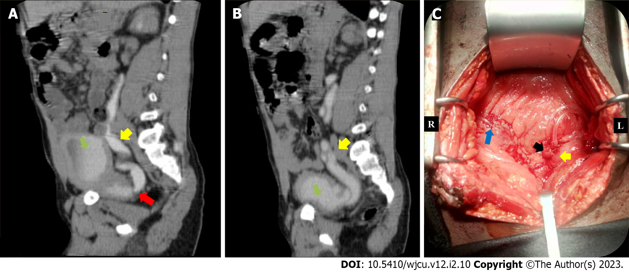
Figure 3 Contrast imaging and intraoperative image.
Sagittal views of computerized tomography scan and ureteroneocystostomy. A: Computerized tomography scan, sagittal view showing right ureter (yellow arrow) insertion into the region of prostatic urethra (red arrow) and bladder (green arrow); B: Computerized tomography scan, sagittal view demonstrating left duplex ureter (yellow arrow) insertion into the bladder; C: Intraoperative view of right ureteroneocystostomy (blue arrow) and left duplex ureteroneocystostomy (black and yellow arrows).
- Citation: Khalid A, Nasiru M, Abdulwahab-Ahmed A, Muhammad AS, Agwu NP, Lukong CS. Phallic rubber band application to prevent enuresis unusual cause of urethral stricture in a child: A case report. World J Clin Urol 2023; 12(2): 10-16
- URL: https://www.wjgnet.com/2219-2816/full/v12/i2/10.htm
- DOI: https://dx.doi.org/10.5410/wjcu.v12.i2.10


