Revised: November 23, 2011
Accepted: March 3, 2012
Published online: April 18, 2012
Research in different areas of orthopedic and trauma surgery requires a methodology that allows both a more economic approach and the ability to reproduce different situations in an easy way. Simulation models have been introduced recently in bioengineering and could become an essential tool in the study of any physiological unity, regardless of its complexity. The main problem in modeling with finite elements simulation is to achieve an accurate reproduction of the anatomy and a perfect correlation of the different structures, in any region of the human body. Authors have developed a mixed technique, joining the use of a three-dimensional laser scanner Roland Picza captured together with computed tomography (CT) and 3D CT images, to achieve a perfect reproduction of the anatomy. Finite element (FE) simulation lets us know the biomechanical changes that take place after hip prostheses or osteosynthesis implantation and biological responses of bone to biomechanical changes. The simulation models are able to predict changes in bone stress distribution around the implant, so allowing preventing future pathologies. The development of a FE model of lumbar spine is another interesting application of the simulation. The model allows research on the lumbar spine, not only in physiological conditions but also simulating different load conditions, to assess the impact on biomechanics. Different degrees of disc degeneration can also be simulated to determine the impact on adjacent anatomical elements. Finally, FE models may be useful to test different fixation systems, i.e., pedicular screws, interbody devices or rigid fixations compared with the dynamic ones. We have also developed models of lumbar spine and hip joint to predict the occurrence of osteoporotic fractures, based on densitometric determinations and specific biomechanical models, including approaches from damage and fracture mechanics. FE simulations also allow us to predict the behavior of orthopedic splints applied to the correction of deformities, providing the recovering force-displacement and angle-moment curves that characterize the mechanical behavior of the splint in the overall range of movement.
- Citation: Herrera A, Ibarz E, Cegoñino J, Lobo-Escolar A, Puértolas S, López E, Mateo J, Gracia L. Applications of finite element simulation in orthopedic and trauma surgery. World J Orthop 2012; 3(4): 25-41
- URL: https://www.wjgnet.com/2218-5836/full/v3/i4/25.htm
- DOI: https://dx.doi.org/10.5312/wjo.v3.i4.25
Research in different fields concerning orthopedic surgery and traumatology requires a methodology that allows a more economic approach and the possibility of reproduction in an easy way in different situations at the same time. Such a method could be used as a guide for research on biomechanics of the locomotor system, both in healthy and pathological conditions, along with the study of performance of different prostheses and implants. To that effect, the use of simulation models, introduced in the field of bioengineering in recent years, can undoubtedly mean an essential tool to assess the best clinical option, provided that it will be accurate enough in the analysis of specific physiological conditions concerning certain pathology.
The finite element method (FEM) was originally developed for solving structural analysis problems relating to mechanics, civil and aeronautical engineering. The paternity of this method is attributed to Turner, who published his first, historic job in 1956[1]. In 1967, Zienkiewicz[2] published the book “The finite element method in structural and continuum mechanics” which laid down mathematical basis of the method. Other fundamental contributions to the development of FEM took place about the same time[3-6].
Finite element (FE) simulation has proved to be especially suitable in the study of the behavior of any physiological unit, despite its complexity. Nowadays, it has become a powerful tool in the field of orthopedic surgery and traumatology, helping surgeons to have a better understanding of the biomechanics, both in healthy and pathological conditions. FE simulation lets us know the biomechanical changes that occur after prosthesis or osteosynthesis implantation and biological responses of bone to biomechanical changes. It also has an additional advantage in predicting the changes in the stress distribution around the implanted zones, allowing prevention of future pathologies derived from an unsuitable positioning of the prostheses or its fixation. Simulation also allows us to predict the behavior of orthopedic splints, utilized for the correction of deformities, providing the recovering force-displacement and angle-moment curves that characterize the mechanical behavior of the splint in the overall range of movement.
One of the most significant aspects of biomechanical systems is its geometric complexity, which greatly complicates the generation of accurate simulation models. Classic models suffered from this lack of geometrical precision, present even in recent models[7,8], which challenged, in most studies, the validity of the results and their extrapolation to clinical settings.
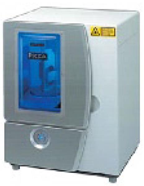
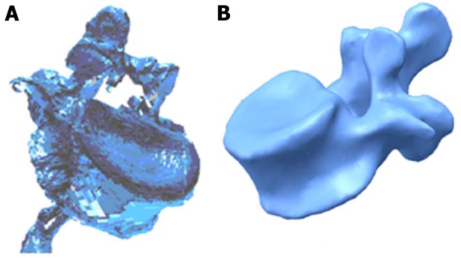
Currently, there are methodologies developed over recent years that avoid such problems, allowing the generation of models with the desired precision in a reasonable time and without excessive cost. Thus, the use of scanners together with three-dimensional images obtained by computed tomography (CT) allow the making of geometric models that combine high accuracy in the external form with an excellent definition of internal interfaces. The method requires not only appropriate software tools capable of processing images, but also compatibility with the programs used later to generate the finite element model. For example, the initial result obtained by a three-dimensional laser scanner Roland Picza (Figure 1) from an anatomical model of the lumbar spine Somso brand QS-15 (Figure 2) is shown in Figure 3A.
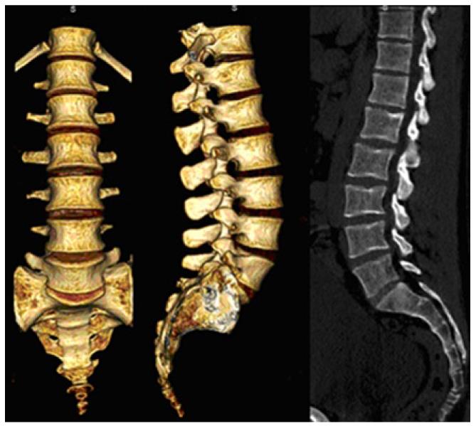
After processing by Dr. Picza 3 and 3D Editor programs, we get the final result in Figure 3B, which shows the geometric precision obtained. In these models, the characterization of the internal structure is made by three dimensional CT from images like that shown in Figure 4. An alternative to the above procedure is the use of 3D geometrical reconstruction programs, for example, MIMICS[9]. In any case, the final result is a precise geometrical model which serves as a basis for the generation of a finite elements mesh.
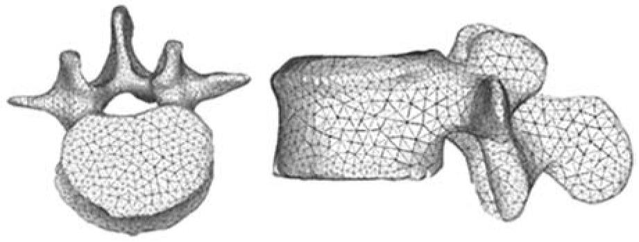
In view of the difficulties experienced in living subjects, FE simulation models have been developed to carry out research on biomechanical systems with high reproducibility and versatility. These models allow repeating the study as many times as desired, being a non-aggressive investigation of modified starting conditions. However, work continues on the achievement of increasingly realistic models that allow putting the generated results and predictions into a clinical setting. To that purpose, it is mainly necessary to use meshes suitable for the particular problem, as regards both the type of elements and its size. It is always recommended to perform a sensitivity analysis of the mesh to determine the optimal features or, alternatively, the minimum necessary to achieve the required accuracy. In Figure 5, a FE mesh of a lumbar vertebral body using tetrahedron type elements is shown. It can be seen that the element size allows the geometry of the vertebra to be depicted with little error, compared with Figure 3B.
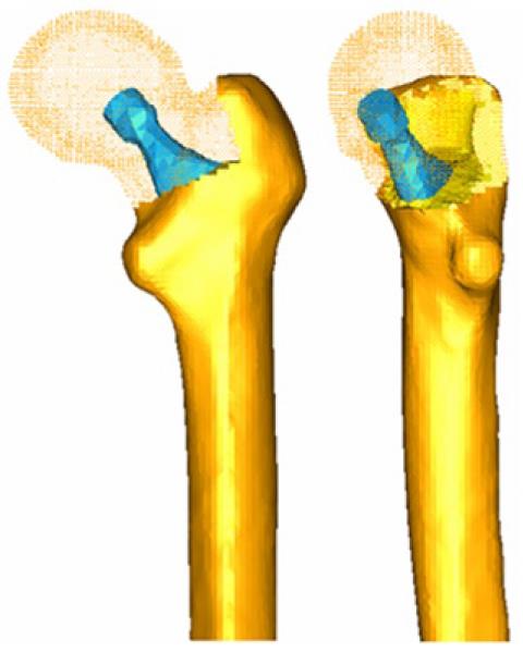
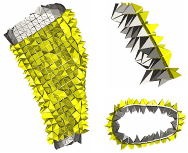
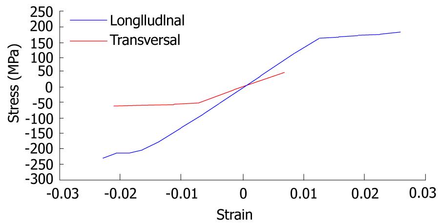
A key issue in FE models is the interaction between the different constitutive elements of the biomechanical system, especially when it comes to conditions which are essential in the behavior to be analyzed. Thus, in Figure 6, a FE mesh of the proximal femur with a cementless stem in place is shown. The biomechanical behavior of this type of implant depends basically on the conditions of contact between the stem and bone, so that the correct simulation of the latter determines the validity of the model. In Figure 7, the stem-femur contact interface can be seen, defined by the respective surfaces and the frictional conditions needed to produce the press-fit which is achieved at surgery. Finally, in FE simulation models, the appropriate characterization of the mechanical behavior of the different materials, usually very complex, is essential. So, the bone exhibits an anisotropic behavior with different responses in tension and compression (Figure 8). Moreover, it varies depending on the bone type (cortical or cancellous) and even along different zones in the same specimen, as in the vertebrae[10]. This kind of behavior is reproducible in a reliable way in the simulation but it leads to an excessive computational cost in global models. For this reason, in most cases and especially in long bones, a linear elastic behavior in the operation range concerning strains and stresses is considered.
In soft tissues, the behavior is even more complex, usually as a hyperelastic or hypoelastic material. This is the case of ligaments (Figure 9), cartilages and muscles, also including a reological effect with deferred strains when the load conditions are maintained (viscoelastic behavior). A special case arises in the intervertebral discs, where nucleus and annulus present totally different features: while the nucleus behaves as an incompressible fluid, the annulus could be considered as a two-phase material with a flexible matrix and a set of fibers with only tension hyperelastic behavior.
This inherent complexity to the different biological tissues, reproducible in reduced or local models, is very difficult to be considered in global models as used to analyze prostheses and implants because the great amount of non-linearities make the convergence practically unfeasible. On the other hand, it leads to a prohibitive computational cost, only possible to be undertaken by supercomputers.
Bone is living tissue and undergoes a constant process of replacement of its structure, characterized by bone resorption and new bone formation, without changing morphology. This process is called bone remodeling. On the other hand, bone adapts its structure, according to Wolff’s Law, to the forces and biomechanical loads received[11]. In a normal hip joint, loads from the body are transmitted to the femoral head, then to the medial cortical bone of femoral neck towards the lesser trochanter, where they are distributed by the diaphyseal bone[12].
The implantation of a cemented or cementless femoral stem produces a clear alteration of the physiological transmission of loads as these are now passed through the prosthetic stem, in a centripetal way, from the central marrow cavity to the cortical bone[13]. These changes of the normal biomechanics of the hip bone leads to a phenomenon called adaptive remodeling[14], since bone has to adapt to the new biomechanical situation. Remodeling is a multifactorial process dependent on both mechanical and biological factors. Mechanical factors are related to the new distribution of loads caused by implantation of the prosthesis in the femur, the physical characteristics of the implant (size, implant design and alloy), and the type of anchoring in the femur: metaphyseal, diaphyseal, hybrid etc[15-20]. Biologics are related to age and weight of the individual, initial bone mass, quality of primary fixation and loads applied to the implant. Of these biological factors, the most important is initial bone mass[16].
Different models of cementless stems have tried to achieve perfect load transfer to the femur, mimicking the physiological transmission from the femoral calcar to the femoral shaft. The main objective was to avoid stress-shielding, since the absence of physiological transmission of loads and lack of mechanical stimulus in this area causes proximal bone atrophy.
Cemented stem fixation is achieved by the introduction of cement into bone, forming a bone-cement interface. Inside the cement mantle, a new interface is made up between cement and stem. It might seem that the cement mantle enables better load distribution in the femur; however, the design, material and surface of prostheses play an important role in transmission and distribution of charges, influencing bone remodeling[21,22].
Long-term follow-up of different models of cementless stems have shown that this is not achieved and to a greater or lesser extent, the phenomenon of stress-shielding is present in all the models and therefore the proximal bone atrophy. It is interesting to know, not only the stress-shielding and subsequent proximal bone atrophy in cemented stems, but also the long-term behavior of cement-bone and stem-cement interfaces. This requires long-term studies monitoring the different models of stems.
FE simulation allows us to study the long term biomechanical behavior of any type of stem, cemented or cementless, and predict the impact of biomechanics on the femur, with its consequent effects on bone remodeling. So, we have developed FE models to study the biomechanical behavior of cemented and cementless stems. Our models have been validated with long-term DXA studies of patients who were treated with different types of femoral stems[23,24].
The development of the model of a healthy femur is crucial to make the whole process of simulation accurate and to obtain reliable results. A femur from a 60 year old man who died in traffic accident was used to build the model. Firstly, each of the parts necessary to set the final model was scanned using a three dimensional scanner, Roland Picza brand. As a result, we get a cloud of points which approximates the scanned geometry. These surfaces must be processed through the programs Dr.Picza-3 and 3D-Editor. This will eliminate the noise and performs smooth surfaces, resulting in a geometry that reliably approximates to the actual geometry.
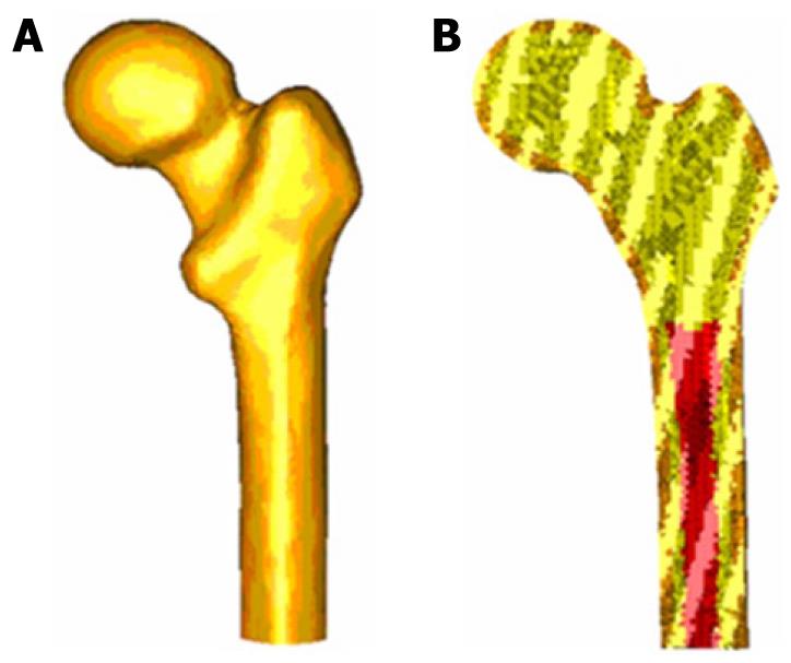
CT scans and 3D-CT reconstructions were taken from the femur to determine the geometry of the cancellous bone, allowing a perfect model of this part of the bone. For a precise geometry, splines are plotted according to the tomograms and then the cancellous surface is modeled. This area represents the separation between cortical and cancellous bone. The meshing is performed by using I-deas program[25], which creates two groups of elements (cancellous and cortical). Taking cancellous bone elements as the start point, a third group of elements is selected by applying the properties of bone marrow. The mesh is based on tetrahedral solid elements with linear approximation, obtaining a total of 408 518 elements (230 355 elements for cortical bone, 166 220 elements for cancellous bone and 11 943 elements for bone marrow) (Figure 10).
Different publications[26] were consulted to obtain the properties of bone material. Table 1 summarizes the mechanical properties values used in biological materials, which have been simplified to consider bone as isotropic and linear elastic material. The main features of each of the boundary conditions are following.
| Material | Young modulus (MPa) | Poisson ratio | Maximum compression stress (MPa) | Maximum tension stress (MPa) |
| Cortical bone | 20 000 | 0.3 | 150 | 90 |
| Cancellous bone | 959 | 0.12 | 23 | |
| Bone marrow | 1 | 0.3 |
The middle zone has been clamped instead of the distal zone because the middle zone is considered enough away from the proximal bone (Figure 11). This model can be compared with others that have been clamped at a distal point since the loads applied practically coincided with the femoral axis direction, thus reducing the differences in final values.
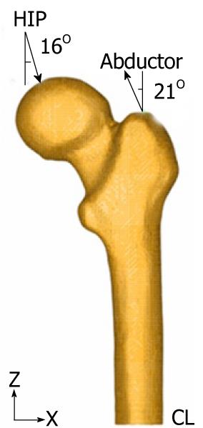
Forces generated by the abductor muscles are applied on the greater trochanter, in agreement with most authors’ opinion[27,28]. Generally, muscle strength generated in the hip joint is 2 times the body weight and this produces a reaction in the femoral head that accounts for 2.75 times the body weight. However, when the heel impacts on the ground in the double support stage of the gait, the load increases up to 4 times the body weight. The latter case, being the worst one, has been considered to impose the boundary conditions. A body weight of 79.3 kg for cementless stems and 73.0 kg for cemented stems has also been considered. Those were the average values obtained from the clinical sample to be contrasted with the simulation results. The load due to the abductor muscles, accounting for 2 times the corporal weight, is applied to the proximal area of the greater trochanter, at an angle of 21 degrees, as shown in Figure 11.
As already mentioned, we studied the case of a person to 79.3 kg in cementless stems and 73.0 kg in cemented stems, in the worst case of double support or heel impact stages of the gait. The resultant force on the femoral head would be worth 4 times the body weight (Figure 11).
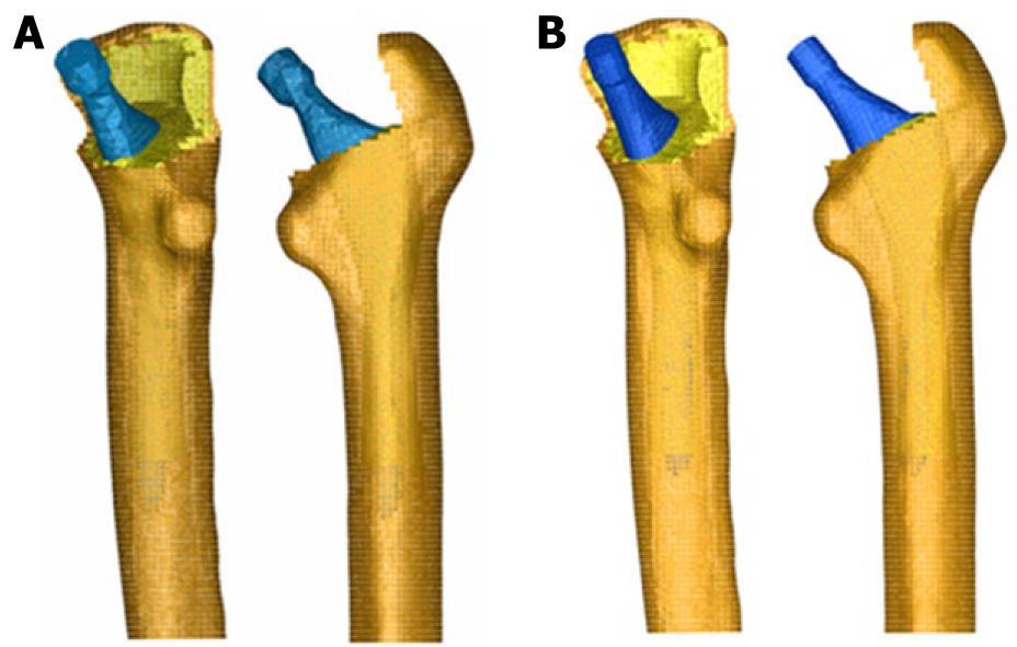
The models generated using I-deas were calculated by means of Abaqus 6.7[29] and the post processing of the results was performed by Abaqus Viewer[29]. These were scanned to obtain its geometry to generate the models from different stems. We studied two cementless stems. Both of them were anatomically shaped, metaphyseal anchored and coated with HA in their metaphyseal zone (ABG I and ABG II). The size used was similar in both models; however, the alloy, geometry, length, thickness and distal diameter were different. For cemented stem models, we chose the cemented anatomical stem ABG and the Versys straight polished stem. After obtaining the geometry of the different stems, several cadaver femurs were operated on in order to implant each of the prostheses, in the same way as one would carry out a real hip replacement.
Those operated femurs were scanned a second time to use them as a reference in the positioning of the prostheses. We used three meshes generated by the I-deas program for every model: healthy femur, femoral stem and operated femur. The mesh of the healthy femur and the mesh of the operated femur were superimposed and then the healthy femoral epiphysis was removed in an identical way as is done during surgery, so as to insert the prosthesis. Afterwards, the stem was positioned in the femur, always taking the superimposed mesh of the operated femur as a base (Figure 12).
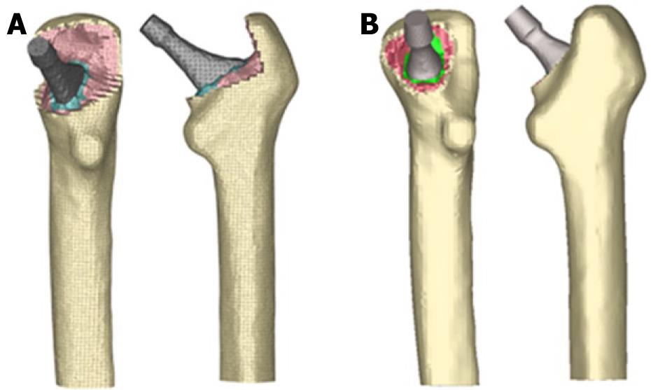
The previous process for modeling the cadaveric femur for cementless stems was repeated only for cortical bone, while the cancellous bone was modeled again in such a way that it fitted perfectly to contact with the prostheses. The Abaqus 6.7 program was utilized for calculation and simulation of the previously generated models and the Abaqus Viewer was used for viewing the results. Union between the stems and the cancellous bone was not considered but contact conditions were defined with a constant 0.5 friction coefficient, simulating the perfect press-fit setting. The final model with ABG-I stem comprises a total of 60 401 elements (33 504 for cortical bone, 22 088 for cancellous bone and 4809 for ABG-I stem). The final model with the ABG-II stem is made up of 63 784 elements (33 504 for cortical bone, 22 730 for cancellous bone and 7550 for ABG-II stem). Figure 13 shows both FE models obtained for cementless prostheses.
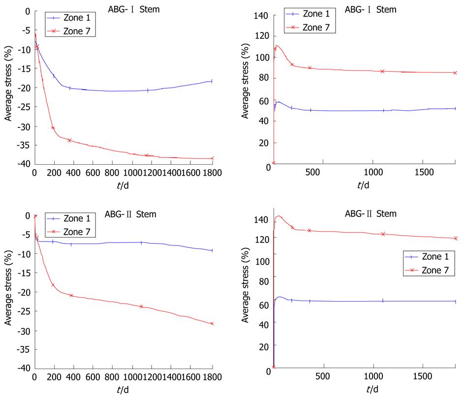
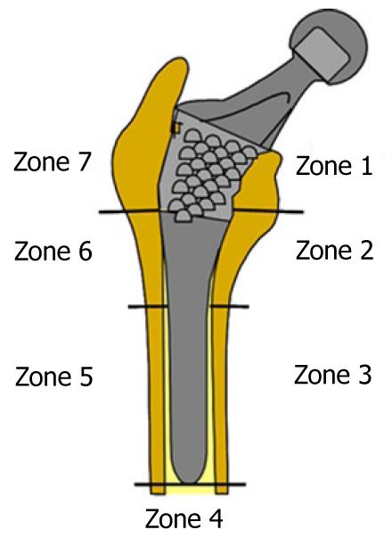
Calculation was performed using the program Abaqus 6.7. Both prostheses were simulated with the same mechanical properties; thus, the result shows the influence of stem geometry on the biomechanical behavior. Figure 14 shows the change (%) in bone mineral density (BMD) and average von Mises stress corresponding to the Gruen proximal zones (1 and 7) for every cementless stem model, being the most representative concerning stress-shielding and taking the pre-operative data as reference. It can be confirmed, for both stems, that the maximum decrease in BMD is achieved in zone 7. This reduction in BMD is bigger in the ABG-I than in ABG-II stem.
The process of modeling was similar in cemented stems, varying the surgical cut in the femoral neck of the healthy femur. Each stem was positioned into the femur, always taking the superimposed mesh of the operated femur as a base (Figure 15). In the previous process of modeling on the cadaveric femur, only the cortical bone was used. The cancellous bone was modeled again, taking into account the cement mantle surrounding the prosthesis and the model of stem (ABG or Versys), so as to obtain a perfect union between cement and cancellous bone. The cement mantle was given a similar thickness, in mm, which corresponds to that usually achieved in patients operated on, different for each of the stem models studied and each of the areas of the prosthesis, so that the simulation model was as accurate as possible.
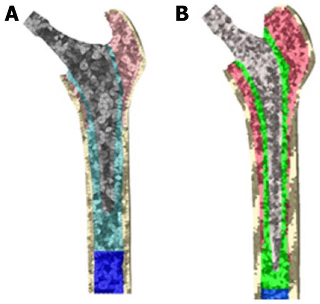
It is not necessary to define contact conditions between the cancellous bone and the stem in models of cemented prostheses. In this type of prosthesis, the junction between these two elements is achieved by cement, which in the EF model should simulate conditions of perfect union between cancellous bone, cement and stem. It has also been necessary to model the diaphyseal plug that is placed in actual operations to prevent the spread of the cement down to the femoral medullary canal. Figure 16 shows the longitudinal sections of the final models.
Both models were meshed with tetrahedral solid elements linear type, with a total of 74 192 elements in the model for ABG-cemented prosthesis (33 504 items cortical bone, cancellous bone 17 859, 6111 for the ABG stem-cement, cement 13 788 and 2930 for diaphyseal plug) and 274 651 in the model for prosthetic Versys (119 151 items of cortical bone, cancellous bone 84 836, 22 665 for the Versys stem, 44 661 for the cement and 3338 in diaphyseal plug). In Figure 17, both models for cemented stems are shown.
Calculation was performed using the program Abaqus 6.7. Both prostheses were simulated with the same mechanical properties; thus, the result shows the influence of stem geometry on the biomechanical behavior. Figure 18 shows the variation (%) of bone mass and average von Mises stress (%) in each of the Gruen zones for each of the models of cemented prostheses, with reference to the preoperative time. It can be seen that for both stems, the maximum decrease in bone mass occurred in Zone 7. This decrease in bone mass is greater in the Versys (Zimmer) model than in the Anatomique Benoist Girard (ABG) (Stryker) stem.
Prior to the development of our FE models, several long-term studies of bone remodeling after the implantation of two different cementless stems, ABG I and ABG II, were performed[30-32]. These studies were performed using DXA, a technique that allows an accurate assessment of bone density losses in the different Gruen zones (Figure 19). As a reference to explore this evolution, we take the postoperative value obtained in control measurements and those obtained from contralateral healthy hip. New measurements were made at 6 mo, one year and 5 years after surgery. The ABG II stem is an evolution of the ABG I, which has been modified both in its alloy and design. The second generation prosthesis ABG-II is manufactured with a different titanium alloy from that used in the ABG-I. The prosthetic ABG-I stem is made with a Wrought Titanium alloy (Ti 6Al-4V), of which elasticity modulus is 110 GPa. Meanwhile, the TMZF alloy, which is used on the ABG-II stem, has a Young’s modulus of 74-85 GPa, according to the manufacturer information, using a mean value of 79.5 GPa in the different analyses. On the other hand, the ABG II stem has a new design with less proximal and distal diameter, less length and the shoulder of stem has been redesign to improve osteointegration in the metaphyseal area.
In our Dual Energy X-rays Absorptiometry (DXA) studies, directed to know the loss of bone mass in the different zones of Gruen caused by the -stress-shielding, we found that ABG II model produces less proximal bone atrophy in post-operative measurements for similar follow-up periods. In the ABG II model, we keep finding studies with DXA proximal bone atrophy, mainly in zones 1 and 7 of Gruen, but with an improvement of 8.7% in the values obtained in ABG I series. We can infer that improvements in the design of the stem, with a narrower diameter in the metaphyseal area, improves the load transfer to the femur and therefore minimizes the stress-shielding phenomenon, resulting in a lower proximal bone atrophy because this area receives higher mechanical stimuli. These studies for the determination of bone mass in Gruen zones and the comparative study of their postoperative evolution over 5 years have allowed us to draw a number of conclusions: (1) bone remodeling after implantation of a femoral stem is finished one year after surgery; and (2) variations in bone mass after the first year are not significant.
The importance of these studies is that objective data from a study with a series of patients allow us to confirm the existence of stress-shielding phenomenon and quantify exactly the proximal bone atrophy that occurs. At the same time, they have allowed us to confirm that the improvements in the ABG stem design mean better load transfer and less stress-shielding phenomenon in practice when using the ABG-IIstem.
DXA studies have been basic to validate our FE models because we have handled real values of patients’ bone density, which allowed us to measure mechanical properties of real bone in different stages. Through computer simulation with our model, we have confirmed the decrease of mechanical stimulus in femoral metaphyseal areas, with a higher stimulus in ABG-IItype stem, which corresponds exactly with the data obtained in studies with DXA achieved in patients operated on with both models stems.
In the case of cemented stems, densitometric studies were performed with two different types of stem: one straight (Versys, manufactured in a cobalt-chromium alloy) and the other anatomical (ABG, manufactured in forged Vitallium patented by Stryker Howmedica). It carried on the same methodology used in the cemented stems series but postoperative follow-up was only one year long. Densitometric studies previously made with cementless stems allow us to confirm that bone remodeling is done in the first postoperative year, a view shared by most authors. So, we accept that bone mineral density values obtained one year after surgery can be considered as definitive. As in cementless models, densitometric values have been used for comparison with those obtained in the FE simulation models. Our studies confirmed that the greatest loss of bone density affects area 7 of Gruen ABG[33], which means that stress-shielding and atrophy of metaphyseal bone also occurs in cemented prostheses. This phenomenon is less severe than in non-cemented stems; therefore, we can conclude that the load transfer is better with cemented stems than with cementless stems. The findings of proximal bone atrophy, mainly in area 7, agree with those published by other authors[34,35]. We have also found differences in the rates of decrease in bone density in area 7 of Gruen, which were slightly lower in the anatomical ABG stem than in the Versys straight stem. This also indicates that the prosthesis design has influence in the remodeling process and that mechanical stimuli are different and related to the design.
The spine is a complex anatomical structure that has three dimensional movements, maintains the erect posture of the individual and supports a significant load. In its central part, the spinal canal forms to contain the nervous structures; therefore, it has to be flexible to perform movements and maintain stability and protect nervous structures. The spine changes its mechanical properties depending on the loads; therefore, it behaves as a viscoelastic structure[36]. For these special features, the study of its biomechanics in its three areas is a very complex matter and it is very difficult to reproduce it for in vivo or in vitro studies. Lumbar spine has been widely studied with a large variability of results in many papers.
Biomechanics of the lumbar spine has been studied in cadaveric specimens[37] but lack of flexibility makes it difficult to reproduce the range of motion presented by living persons. In vivo studies have been made by various methods (radiographic, computerized axial tomography (CAT), magnetic resonance imaging (MRI), television (TV) and computer, electrogoniometer, inclinometer, etc.). The results are extremely variable, even for the same person throughout the day[38], and also have different values on account of age and existing pathology[39]. Animal spines have also been used for these biomechanical studies, despite major differences with the human lumbar spine[40].
Because of the difficulties of research in living persons, their variability with published mixed results, the problems with in vitro studies and the differences between the human and animal column, we developed simulation models using FE. This model allows research on the lumbar spine in physiological conditions to simulate different load conditions and study the impact on biomechanics. We can also simulate the disc degeneration, to a greater or lesser degree, and study the impact on adjacent elements to a degenerated disc. Finally, the model may be useful to test different fixation systems, as a pedicular screw, an interbody device or rigid fixations compared with the dynamics.
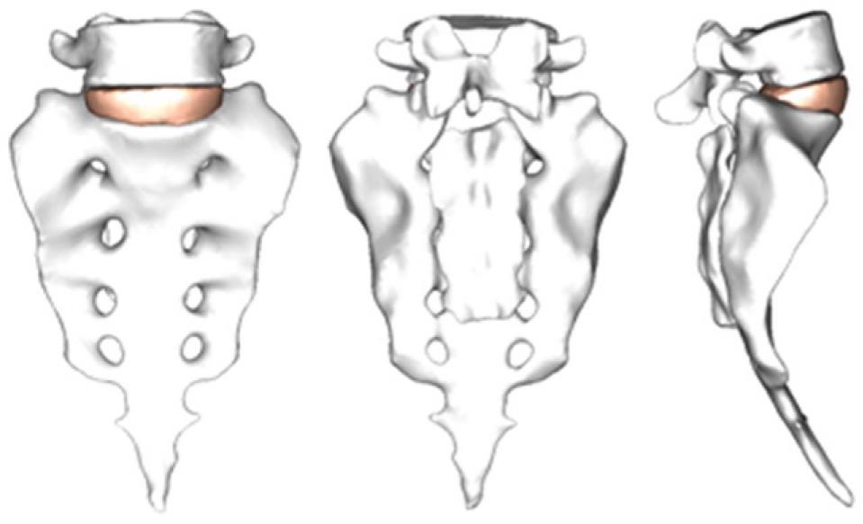
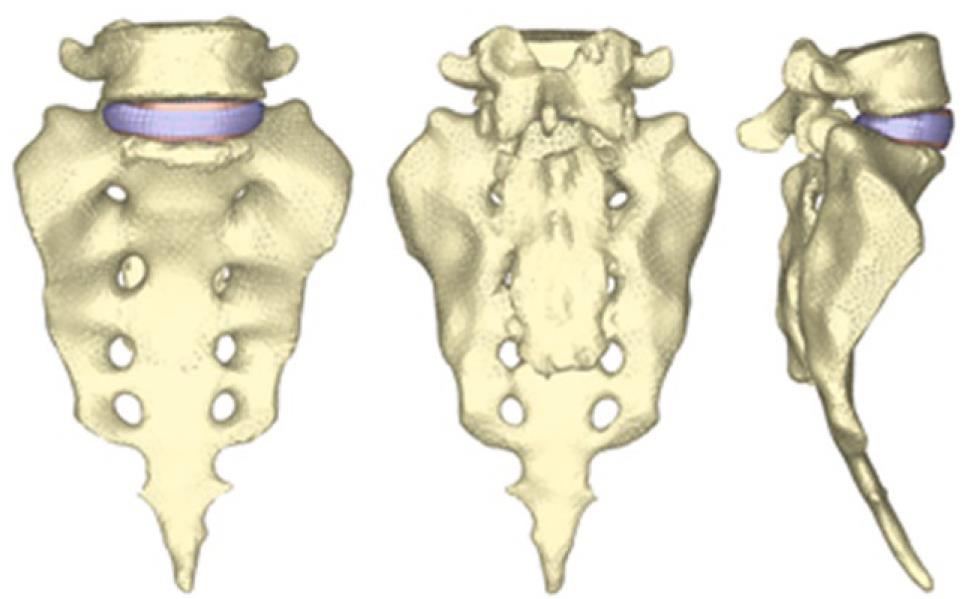
By using the methodology described in paragraph 1, it is possible to obtain the geometrical model corresponding to the S1-L5 functional unit (Figure 20). The mesh of the vertebrae is made by means of tetrahedrons with linear approximation in the I-deas program (I-deas, 2007) with a size thin enough to allow a smooth transition from the zone of the exterior cortical bone to the zone of the interior cancellous bone; this transition was obtained by means of statistical averages from CTs of vertebrae in healthy individuals. Disc meshes are essential for a correct reproduction of the biomechanical behavior of the functional unit analyzed. In order to do this, each disc is divided into nucleus pulposus and annulus fibrosus with commonly accepted dimensions[41]. Each part is meshed separately so that mesh sizes should match each other and with the vertebrae, getting the complete FE model (Figure 21).
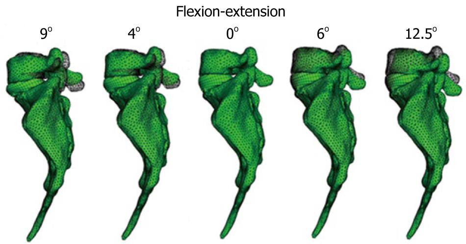
The material properties of bone were taken from the literature. The nucleus pulposus in the discs behaves like a non-compressible fluid, which upon being compressed expands towards the exterior tensioning the fibers of the annulus. Fibers of the annulus show a hyperelastic behavior, but only in tension. The correct interaction between the different elements (vertebrae, discs and ligaments) is essential. Conditions of union between the vertebral body and the intervertebral disc have been established, as it is the most representative of the real anatomy. Finally, contact conditions have been established between the different apophyses which provide a global stability. In order to verify the effectiveness of the fixation, flexion-extension movement has been analyzed as the most representative (Figure 22). As boundary conditions, displacements in the wings of sacrum have been prevented.
Muscle and ligament forces are adjusted to the appropriate values to obtain the required movement ranges. So, the deformed shapes shown in Figure 23 are achieved. Calculation and post-processing are carried out using the Abaqus program.
Once the healthy model has been adjusted and vali-dated, it is possible to simulate new conditions corresponding to different levels of disc degeneration. So, after decreasing the mechanical properties of the annulus and fibers in the disc, according to the mechanical damage theory, we can measure the changes produced in the different movements.
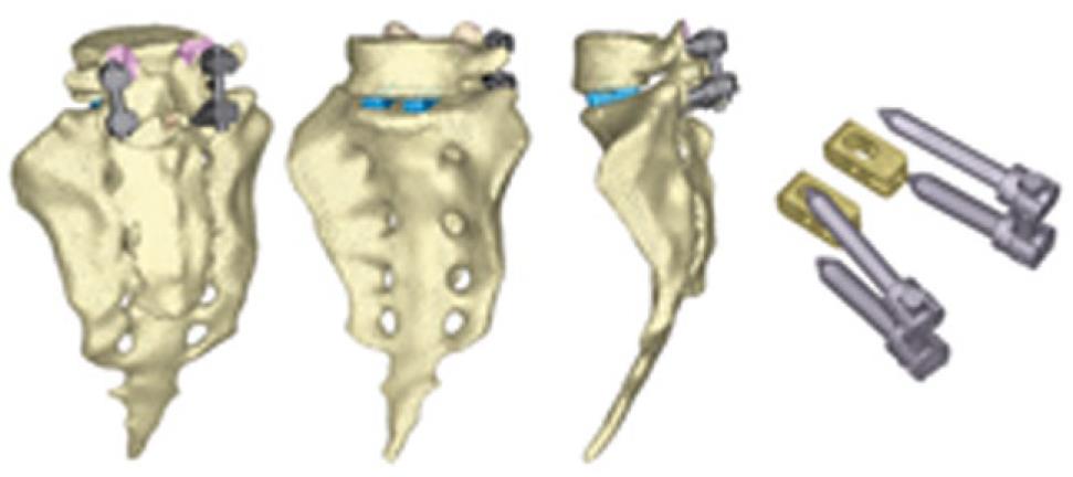
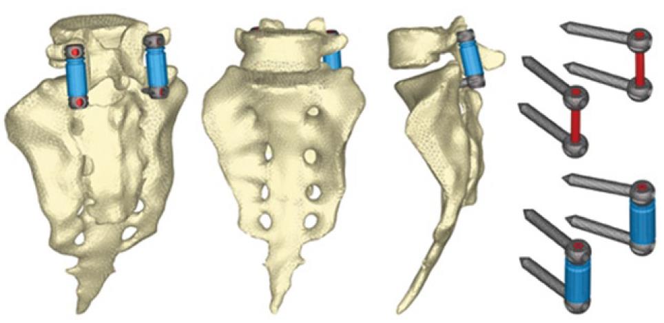
The next step is the study of several types of fixations (rigid and dynamic). Changes induced by surgery must be reproduced in the FE model. To that effect, the holes for the pedicular screws must be generated by removing the elements intersected by the screws and resetting the mesh along the new interfaces. In the same way, pedicular wings must be trimmed to allow the introduction of the screws. With the screws in place, the struts are implemented to obtain the final models (Figures 24 and 25).
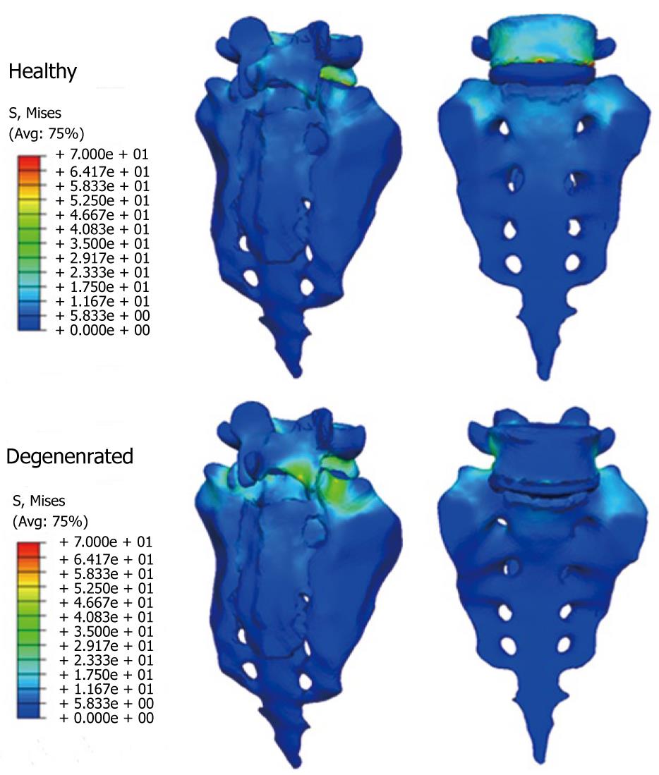
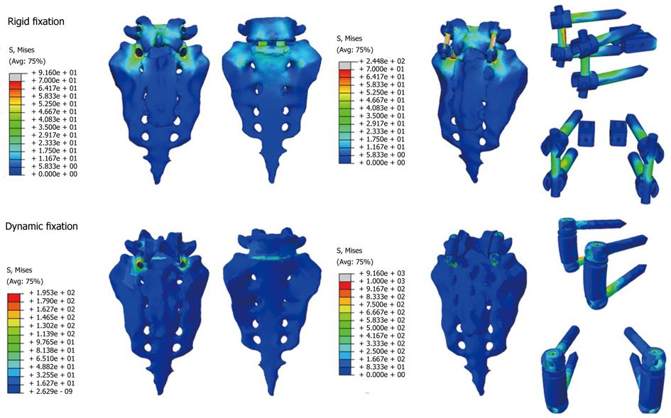
From those new models, the study of the flexion-extension movement can be reproduced in the new conditions, verifying the changes produced as a consequence of the fixations. The results allow comparison of the performance of the different models and, moreover, it is possible to analyze the changes in the local stress distribution around the screws, detecting points of possible future pathologies due to the alterations produced by the presence of the fixations. So, in Figures 26 and 27, the von Mises stress distributions, both in the healthy and in the implanted models, are shown. Comparing both figures, a high stress concentration around the screw root is observed, increasing the maximum value till 400% with respect to the healthy model.
Future research concerns the development of the complete lumbar spine model, from S1 to L1, including ligaments and cartilages, in order to get a better approximation to the real biomechanical behavior.
Current models for prediction of osteoporotic fractures have many limitations. In order to solve this question, this study carried out a predictive model based on the biomechanical failure of the osteoporotic bone. The purpose was to create a simulation of the biological involution of the bone using a finite element model to predict the risk of fracture in the mid-long term. This simulation was adjusted to the clinical features of the patients using DXA values. The physiological curve of BMD, corresponding to the one published in Mazess et al[42], was included for the assessment.
Standard techniques, such as linear or quadratic regression analysis used in our practice, did not provide enough accuracy or reliability to be used in the predictive model. This might be explained by the irregularity of the analyzed curves. In order to analyze continuous curves of BMD resulting from the different treatments applied for osteoporosis, more complex adjustments have been performed. The following have been included in the study[43]: polynomial adjustment, exponential adjustment and asymptotic exponential adjustment. Two conditions were applied to select the proper adjustment: the lower quadratic error rate and the value of Pearson’s correlation coefficient closest to one. In order to assess the outcomes and to establish reliable comparisons, adjustments have been normalized over a period of 10 years.
For the simulation of the degenerative process of the bone, the Karganovin mechanical model was selected[44]. It relates the deformation
D = 1 - κ(εc)γ
The constants κ and γ are dependent on the values of the critical damage, the critical strain and the deformation threshold. So, they depend on the material. Once the model showing the biomechanical failure of the osteoporotic bone has been defined, the risk of fracture can be related to the degree of failure. This may be complicated since it depends on many factors: location and amount of damage, type and extension of charge cycles, and so on. However, since patients with osteoporosis are usually old people with quite standard daily activities and little variability in their way of life, a simplified model could be applied to this situation. A probability model based on the Paris law was selected for this analysis[45]. This law relates the stress intensity factor range to sub-critical crack growth under a fatigue stress regime and is expressed by the equation:
where N is the number of load cycles to fracture, α is the crack length, α and β are material constants and ∆K is the range of the stress intensity factor, defined in fracture mechanics. Based on this law, the calculation of the remaining number of cycles to fracture can be performed in terms of the damage variable D, both for the initial damage and for any situation of non-null damage below the critical crack[43]. The probability of fracture is now normalized, being the value of the critical damage equal to 1 and the null damage equal to 0. Then, this probability of fracture would depend on the number of cycles and on the damage and should be calculated as follows:
According to Taylor[46], a β coefficient with a value of 5 has been used for the cortical bone. For a proper application of this model to real situations the reference value of bone density in each patient is required, since this initial value has been found to be different among the previous published studies. In the subjects for study we have:
Age of the patient: t0
BMD of the patient in t0: ρ0
According to the interpolated natural evolution law, the density corresponding to the age of the patient would be:
So, there is an offset:
and this offset must be added to the BMD curve of the patient:
Nevertheless, information about biomechanical properties of bone and not only BMD values is required for a proper use of the predictive model with finite elements. Therefore, a double conversion seems necessary to obtain. Firstly, the apparent volumetric density of the bone related to the corresponding BMD value; and secondly, the value of Young´s modulus depending on the apparent volumetric density. In the present survey, data published by Herrera et al[23] were used for the study in the femoral bone. Sixty one patients undergoing total hip replacement with a cementless metaphyseal-fitting anatomical femoral stem (ABG I), with a medium age of 59 years, medium weight of 79.3 kg and a minimum follow up of 10 years were collected. Little areas of 30 × 30 pixels in each of the Gruen areas were studied for an accurate assessment of BMD. A Hologic QDR 1000 DXA scan (Hologic Inc., Waltham, MA) was used for these measurements. BMD values in the healthy femoral bone were also collected and compared to the apparent volumetric densities and to the Young´s modulus values of the corresponding Gruen areas in the pathologic femoral bone. Carter and Hayes criteria[47] was applied, establishing the relation of the apparent volumetric density with Young´s modulus for low deformation velocities (0.01):
Furthermore, according to experimental results, the association between the values of BMD and the apparent volumetric density is expressed as follows:
The corresponding values in the different Gruen areas can be obtained according to this criterion using the data from Herrera et al[23] as a reference. Thus, for example, for one patient with a BMD of 842 mg/cm2 in the femoral neck (Gruen zone 7), the corresponding values can be seen, as shown in Table 2.
| Gruen area | BMD hologic (mg/cm2) | Apparent volumetric density (gr/cm3) | Young´s modulus (MPa) |
| 1 | 554 | 1306 | 6400 |
| 2 | 773 | 1472 | 9167 |
| 3 | 1009 | 1620 | 12 229 |
| 4 | 1123 | 1684 | 13 726 |
| 5 | 1080 | 1660 | 13 161 |
| 6 | 920 | 1567 | 11 064 |
| 7 | 842 | 1518 | 10 063 |
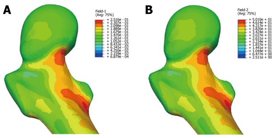
During the study period, the Young´s modulus values for each Gruen area can be obtained using the adequate curve of evolution and taking these data as a reference. Based on tetrahedral elements with linear approximation, the finite element model of the proximal third of the femur was built, taken from Ibarz[48]. Up to 408.094 elements and 75.223 nodes are contained into the mesh. Different areas can be found: cortical bone, cancellous bone and bone marrow. In addition, the cortical bone area has been divided into the 7 zones of Gruen. The biomechanical properties of each of these areas have been obtained from the evolutionary algorithm. All the materials have been considered to show linear elastic behavior. Damage and probability of fracture maps can be represented for any time along the study, as shown in Figure 28.
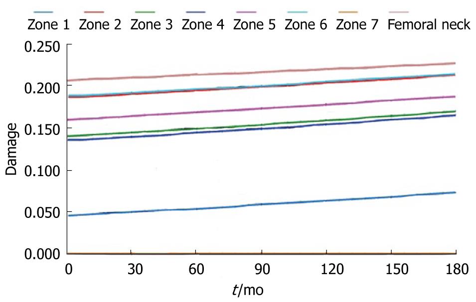
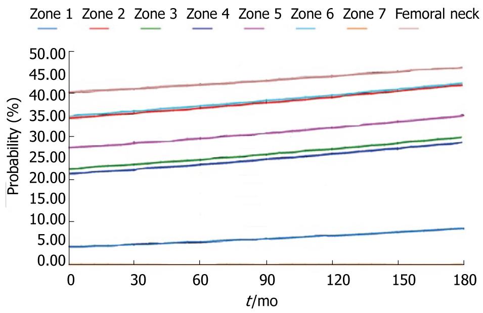
The physiological curve shows a substantial and maintained decline of BMD with a significant increase of the risk of fracture. Similar comparisons can be made for different magnitudes (Figures 29 and 30).
In the pathology of the hand, there is often joint stiffness, usually post-traumatic, causing vicious positions and loss of mobility of the joints. Also, rheumatic disease that affects the joints of the hand can cause deformity and changes in normal joint alignment. The worst situation occurs when these alterations produce flexion stiffness of the joints. In the treatment of articular rigidities, the usual therapy consists of the application of splints, utility of which is guaranteed by different clinic studies that demonstrated its efficacy in most of the pathologies[49]. The mission of the orthopedicsplints is relieve the strength they have or to keep a constant tension, in a determinate mode in the joints and stimulate, that way, the histic changes which allow the stretching of the capsule and joint structures until the deformity is corrected. Among all the different pathologies affecting the hand due to traumas or sickness, one of the more frequent is the contracture by flexion of the proximal interphalangeal joint (AIP). This joint and its mobility are one of the most important factors in the hand functionality.
The use of materials with shape memory superelastic like NiTi alloys for the construction of orthopedic splints is a possibility with great expectations for the future. The experience of the authors in the design of other devices based on the NiTi alloy[50-53] makes it possible to carry out the proposed design of a finger splint for the treatment of the contracture in flexion of the PIP joint. NiTi is an equiatomic alloy of nickel and titanium (commercially known as Nitinol), discovered in the United States Naval Ordinance Laboratory[54]. It belongs to a group of materials with shape memory (SMA). Basically, these alloys have the attribute of being able to recover a previously defined form when the material is subjected to an adequate thermal treatment; associated to this behavior, the material has a super elasticity which lends to the property of withstanding large elastic deformations with relatively low tensions. This property is due to the change of phase which the material undergoes when it is subjected to tension[55].
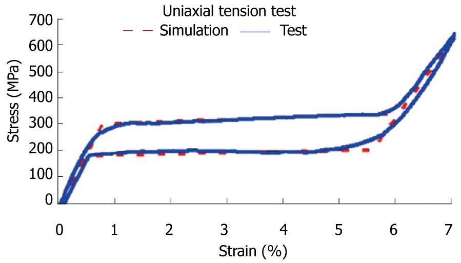
The first step corresponds to characterization of the basic behavior of the material because the mechanical properties of NiTi are very sensitive to little changes in the alloy composition. For this reason, it is necessary to carry out tension-compression uniaxial standard test in the overall range of strains, obtaining the whole behavior curve, both for loading and unloading processes. With this purpose, a universal machine INSTRON 5565 was used to test standard test specimens obtained from shells 1 mm width, corresponding to a reference alloy (50.8% Ni, 49.2% Ti) supplied by the company Memory Metalle GBMH. This alloy exhibits a superelastic behavior at environment temperature. In every test, a complete loading-unloading cycle with displacement control is reached until a maximum strain of 7% at 22 °C. In Figure 31, the tension curve is shown, evaluating from that the different mechanical parameters: elastic moduli for martensite and austenite phases (EA, EM), respectively, phase transition stresses (σsAm, σfAM, σsMA, σfMA) and maximum strain
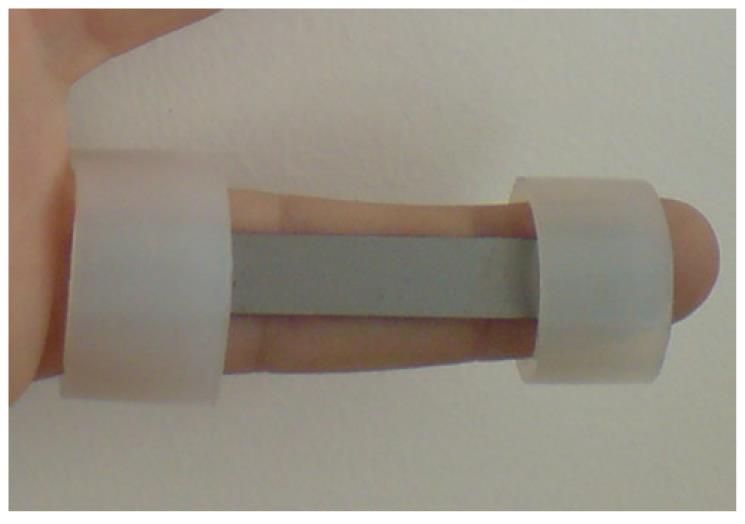
The proposed design uses a thin plate of NiTi, which is fixed onto the finger by means of rings which are responsible for transmitting the recovering force (Figure 32). The mechanism provides a practically one-dimensional bending performance, such that the device presents a mechanical response close to the intrinsic material behavior. This means that the moment-angle curve of the splint has a similar shape to the material tension-deformation curve.
The action of the splints is directly related to the rigidity and in the proposed design the rigidity is directly related to the width, thickness and length, although all of these geometric factors work in an uneven way. An increase in width supposes a linear growth in the recovering force and a better finger support. However, the most important factor used to control the force exerted by the splint is the plate thickness. The device is very sensitive to thickness change, presenting a cubic rate influence. Hence, the greater the thickness, the greater is the effect of straightening and smaller is the risk of breakage, although it is more difficult to bend the splint and fit it in the volar zone of the injured finger. On the contrary, if the thickness is reduced, so are the straightening effect and the risk of breakage increases, although it is easier to bend the splint and fit it on the finger.
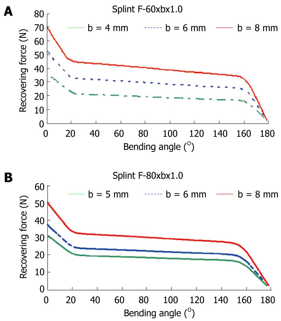
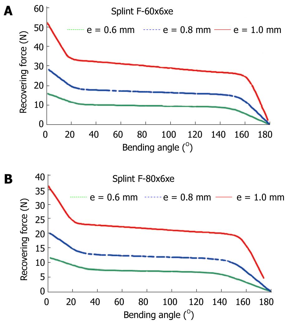
To obtain a design which transmits a force adequate for the recovery of the original position of the finger, a finite elements simulation for a plate of these dimensions, 80 mm × 10 mm × 1 mm, is carried out. A proprietary developed user subroutine is used for the behavior of the material, based on Auricchio`s models[55], in the Abaqus program. Previously, an adjustment of parameters from the results of the tensile test is carried out (Figure 31). Once the model was adjusted, a parametric study was carried out with different values of length, width and thickness for the plate. Figures 33 and 34 show the recovering force-angle curves for the different lengths and widths of the plate, with a fixed thickness of 1 mm, and the recovering force-angle curves for different lengths and thicknesses of the plate, with a fixed width of 6 mm. A practically constant recovering force value can be observed over a wide range of angles that vary between 30º and 150º. This makes it possible to define a characteristic value of recovering force which is ascribed to an angle flexion of 80º. The same occurs in all of the cases analyzed.
In order to design NiTi prosthesis with a recovering force equivalent to the usual in commercial orthosis, it is necessary to adjust the rigidity to bending to the value of this. A parametric simulation has been carried out, covering a range of forces from 5 N to 30 N, with lengths and widths capable of adapting to fingers of different sizes. One main advantage of the proposed designs is that they achieve a practically constant recovering force in a range of angles from 20º to 150º. This makes a therapeutic device possible that practically covers the total recovery of the PIP joint.
Apart from the properties of NiTi, the biomechanical behavior of the proposed prosthesis compared to the commercial ones analyzed is totally different due to its design. Hence, the mechanism to transmit forces onto the finger in the Bort class of splints (and in the majority of those that exist on the market) is based on equilibrium in a simple bending situation, with action (F1, F2) and reaction (F3) in the different parts of the splint (Figure 35A). On the contrary, in the developed prototype, the transmission mechanism is based on equilibrium in pure bending, transmitting both torques on the fixation rings (Figure 35B), through the local equilibrium of forces in the fixation rings.
The common bending mechanism has two important drawbacks: firstly, for a linear behavior spring, the ratio between recovering force and angle is constant in its whole length. Hence, as recovery is produced, the torque transmitted on the joint decreases significantly, even although the distance from the point where the force is applied, F1 on the joint, point A in Figure 35A becomes progressively larger. Its increase does not compensate the loss of force, for which it is necessary to change the splint for another with a different force calibration. Moreover, the forces involved in the equilibrium have components that can generate compression or traction on the joint itself, possibly increasing the damage to the joint.
However, in the mechanism of pure bending as it is directly transmitting torques, the effect on the joint is always the same in all of the recovering range. In addition, forces are not generated on joints; the forces are generated at local level on the fixation rings to give rise to the torques transmitted, acting on zones that are away from the joint and without damaging effects. Thus, the recovering moment is constant in all of the length A1-A-A2 (Figure 35B), without producing undesired effects on the joint. Given that the splint reproduces in the graph moment-angle the basic behavior of NiTi in the tensile test, the recovering moment is practically constant in the all of the range where the splint works. Then the whole treatment is possible with only one splint, and without the need of progressive replacements as the joint recovers.
No other splint available on the market offers this property since all of them are based on materials and mechanisms in which the global result is that of a quasi-linear behavior. This makes it impossible to obtain the curves with a practically null slope in the recovery stage like the one presented here.
Another talking point is the optimum time for the use of straightening splints, which Flower defined as total end range time (TERT), having checked that the longer it is worn daily, the better the results[56,57]. However, Flower himself concludes that in addition to the time of use, the force application parameters are fundamental in attaining a good correction of the deformity[57]. Due to its comfort, the proposed design makes it possible to wear permanently. On the other hand, permanent action dynamic orthosis, regularly used in orthopedics for the PIP joint, are difficult to fit, above all at the level of the proximal phalange despite the therapist being able to choose the size.
On the contrary, the designed splints in this work improve the initial adjustment and make it easier to use for both the patient and the specialist, with no difficulties in its fitting. The proposed design also avoids the harmful effect of pressure on the back of the joint[58] which is produced in the usual static and dynamic systems. The advantages offered against the most frequently used commercial models can be summarised as: (1) better control of the recovering force; (2) maintaining the splint over long periods of time without replacement, since its effect remains unalterable over a wide period of recuperation; (3) ease of use for both the patient and specialist; (4) ease of producing custom made designs for each patient; and (5) significant economic saving in the treatment.
For all of the above mentioned, the proposed design is highly competitive compared to those used presently. Future research concerns the design of alternative geometries and the improvement of the fixation system.
Peer reviewer: Mohit Kumar Patralekh, MS, DNB, 2nd Floor, C1/160-161, Sector-16, Rohini, Delhi 110089, India
S- Editor Yang XC L- Editor Roemmele A E- Editor Yang XC
| 1. | Turner MJ, Clough RW, Martin MC, Topp LJ. Stiffness and deflection analysis of complex structures. J Aeronautical Society. 1956;23:805-823. |
| 2. | Zienkiewicz OC. The finite element method in structural and continuum mechanics. Prentice-Hall, New Jersey, 1967. . |
| 5. | Zienkiewicz OC, Morgan K. Finite element and approximation. New York: John Wiley & Sons 1983; . |
| 6. | Hughes TJR. The finite element method. Prentice-Hall, New Jersey, 1987. . |
| 7. | Guan Y, Yoganandan N, Zhang J, Pintar FA, Cusick JF, Wolfla CE, Maiman DJ. Validation of a clinical finite element model of the human lumbosacral spine. Med Biol Eng Comput. 2006;44:633-641. [PubMed] |
| 8. | Little JP, Adam CJ, Evans JH, Pettet GJ, Pearcy MJ. Nonlinear finite element analysis of anular lesions in the L4/5 intervertebral disc. J Biomech. 2007;40:2744-2751. [RCA] [PubMed] [DOI] [Full Text] [Cited by in RCA: 1] [Reference Citation Analysis (0)] |
| 9. | Available from: http://www.materialise.com. |
| 10. | Denozière G, Ku DN. Biomechanical comparison between fusion of two vertebrae and implantation of an artificial intervertebral disc. J Biomech. 2006;39:766-775. [RCA] [PubMed] [DOI] [Full Text] [Cited by in RCA: 1] [Reference Citation Analysis (0)] |
| 11. | Buckwalter JA, Glimcher MJ, Cooper RR, Recker R. Bone biology. J Bone Joint Surg. 1995;77A:1276-1289. |
| 12. | Radin EL. Biomechanics of the human hip. Clin Orthop Relat Res. 1980;152:28-34. [PubMed] |
| 13. | Markolf KL, Amstutz HC, Hirschowitz DL. The effect of calcar contact on femoral component micromovement. A mechanical study. J Bone Joint Surg Am. 1980;62:1315-1323. [PubMed] |
| 14. | Huiskes R, Weinans H, Dalstra M. Adaptive bone remodeling and biomechanical design considerations for noncemented total hip arthroplasty. Orthopedics. 1989;12:1255-1267. [PubMed] |
| 15. | Sumner DR, Galante JO. Determinants of stress shielding: design versus materials versus interface. Clin Orthop Relat Res. 1992;274:202-212. [PubMed] |
| 16. | Sychterz CJ, Engh CA. The influence of clinical factors on periprosthetic bone remodeling. Clin Orthop Relat Res. 1996;322:285-292. [PubMed] |
| 17. | Rubash HE, Sinha RK, Shanbhag AS, Kim SY. Pathogenesis of bone loss after total hip arthroplasty. Orthop Clin North Am. 1998;29:173-186. [PubMed] |
| 18. | McAuley JP, Sychterz CJ, Engh CA. Influence of porous coating level on proximal femoral remodeling. A postmortem analysis. Clin Orthop Relat Res. 2000;371:146-153. [PubMed] |
| 19. | Gibbons CE, Davies AJ, Amis AA, Olearnik H, Parker BC, Scott JE. Periprosthetic bone mineral density changes with femoral components of differing design philosophy. Int Orthop. 2001;25:89-92. [PubMed] |
| 20. | Glassman AH, Crowninshield RD, Schenck R, Herberts P. A low stiffness composite biologically fixed prosthesis. Clin Orthop Relat Res. 2001;128-136. [PubMed] |
| 21. | Ramaniraka NA, Rakotomanana LR, Leyvraz PF. The fixation of the cemented femoral component. Effects of stem stiffness, cement thickness and roughness of the cement-bone surface. J Bone Joint Surg Br. 2000;82:297-303. [PubMed] |
| 22. | Li MG, Rohrl SM, Wood DJ, Nivbrant B. Periprosthetic changes in bone mineral density in 5 stem designs 5 years after cemented total hip arthroplasty. No relation to stem migration. J Arthroplasty. 2007;22:689-691. [PubMed] [DOI] [Full Text] |
| 23. | Herrera A, Panisello JJ, Ibarz E, Cegoñino J, Puértolas JA, Gracia L. Long-term study of bone remodelling after femoral stem: a comparison between dexa and finite element simulation. J Biomech. 2007;40:3615-3625. [RCA] [PubMed] [DOI] [Full Text] [Cited by in RCA: 1] [Reference Citation Analysis (0)] |
| 24. | Herrera A, Panisello JJ, Ibarz E, Cegoñino J, Puértolas JA, Gracia L. Comparison between DEXA and finite element studies in the long-term bone remodeling of an anatomical femoral stem. J Biomech Eng. 2009;131:041013. [PubMed] |
| 25. | Available from: http://www.ugs.com. |
| 26. | Evans FG. Mechanical properties of bone, Evans F.G. (Ed), Ed. Illinois: Springfield 1973; . |
| 27. | Weinans H, Huiskes R, Grootenboer HJ. Effects of fit and bonding characteristics of femoral stems on adaptive bone remodeling. J Biomech Eng. 1994;116:393-400. [PubMed] |
| 28. | Kerner J, Huiskes R, van Lenthe GH, Weinans H, van Rietbergen B, Engh CA, Amis AA. Correlation between pre-operative periprosthetic bone density and post-operative bone loss in THA can be explained by strain-adaptive remodelling. J Biomech. 1999;32:695-703. [PubMed] |
| 29. | Kerner J; Abaqus. 2009. Available from: http://www.simulia.com. |
| 30. | Panisello JJ, Herrero L, Herrera A, Canales V, Martinez A, Cuenca J. Bone remodelling after total hip arthroplasty using an uncemented anatomic femoral stem: a three-year prospective study using bone densitometry. J Orthop Surg (Hong Kong). 2006;14:32-37. [PubMed] |
| 31. | Panisello JJ, Canales V, Herrero L, Herrera A, Mateo J, Caballero MJ. Changes in periprosthetic bone remodelling after redesigning an anatomic cementless stem. Int Orthop. 2009;33:373-379. [PubMed] |
| 32. | Panisello JJ, Herrero L, Canales V, Herrera A, Martínez AA, Mateo J. Long-term remodeling in proximal femur around a hydroxyapatite-coated anatomic stem: ten years densitometric follow-up. J Arthroplasty. 2009;24:56-64. [PubMed] [DOI] [Full Text] |
| 33. | Joven E. Densitometry study of bone remodeling in cemented hip arthroplasty with stem straight and anatomical. Doctoral Degree Disertation. University of Zaragoza, 2007. . |
| 34. | Arabmotlagh M, Sabljic R, Rittmeister M. Changes of the biochemical markers of bone turnover and periprosthetic bone remodeling after cemented hip arthroplasty. J Arthroplasty. 2006;21:129-134. [PubMed] [DOI] [Full Text] |
| 35. | Dan D, Germann D, Burki H, Hausner P, Kappeler U, Meyer RP, Klaghofer R, Stoll T. Bone loss after total hip arthroplasty. Rheumatol Int. 2006;26:792-798. [PubMed] |
| 36. | Yaszemski MJ, White III AA, Panjabi MM. Biomechanics of spine. F. and Garfin, S.R. (Ed.), Amer. Acad. Orth. Surgeons: Illinois 2002; 17-26. |
| 37. | Panjabi MM, Oxland TR, Yamamoto I, Crisco JJ. Mechanical behavior of the human lumbar and lumbosacral spine as shown by three-dimensional load-displacement curves. J Bone Joint Surg Am. 1994;76:413-424. [PubMed] |
| 38. | Ensink FB, Saur PM, Frese K, Seeger D, Hildebrandt J. Lumbar range of motion: influence of time of day and individual factors on measurements. Spine (Phila Pa 1976). 1996;21:1339-1343. [PubMed] |
| 39. | Sullivan MS, Dickinson CE, Troup JD. The influence of age and gender on lumbar spine sagittal plane range of motion. A study of 1126 healthy subjects. Spine (Phila Pa 1976). 1994;19:682-686. [PubMed] |
| 40. | Kettler A, Liakos L, Haegele B, Wilke HJ. Are the spines of calf, pig and sheep suitable models for pre-clinical implant tests? Eur Spine J. 2007;16:2186-2192. [PubMed] |
| 41. | White AA, Panjabi MM. Clinical Biomechanics of the Spine. Lippincott Williams & Wilkins: Philadelphia 1990; . |
| 42. | Mazess RB, Barden H. Bone density of the spine and femur in adult white females. Calcif Tissue Int. 1999;65:91-99. [PubMed] |
| 43. | López E. Design and development of a model for the prediction of osteoporotic fractures. Application to femoral neck and lumbar spine. Doctoral Degree Disertation, University of Zaragoza, 2009. . |
| 44. | Kargarnovin MH, Bagher-Ebrahimi , Katoozian HR. Damage initiation and growth in a long bone under increasing monotonic loading using the continuum damage mechanics principle. Civil Comp Press, 2006. . |
| 45. | Paris P, Erdogan F. A critical analysis of crack propagation laws. J Basic Engineering. 1963;85:528-534. |
| 46. | Taylor D. Microcrack growth parameters for compact bone deduced from stiffness variations. J Biomech. 1998;31:587-592. [PubMed] |
| 47. | Carter DR, Hayes WC. Bone compressive strength: the influence of density and strain rate. Science. 1976;194:1174-1176. [PubMed] |
| 48. | Ibarz E. Comparative study by means of Finite Elements of the behavior of femoral stems ABG-I and ABG-II. Master Engineering Degree Disertation, University of Zaragoza, 2007. . |
| 49. | Prosser R. Splinting in the management of proximal interphalangeal joint flexion contracture. J Hand Ther. 1996;9:378-386. [PubMed] |
| 50. | Puértolas JA, Pérez-García JM, Juan E, Ríos , R . Design of a suture anchor based on the superelasticity of the Ni-Ti alloy. Biomed Mater Eng. 2002;12:283-289. |
| 51. | Lahoz R, Gracia L, Puértolas JA. Training of the two-way shape memory effect by bending in NiTi alloys. J Eng Mater-T. 2002;124:397-401. |
| 52. | Domingo S, Puértolas S, Gracia-Villa L, Puértolas JA. Mechanical comparative analysis of stents for colorectal obstruction. Minim Invasive Ther Allied Technol. 2007;16:126-136. [RCA] [PubMed] [DOI] [Full Text] [Cited by in RCA: 1] [Reference Citation Analysis (0)] |
| 53. | Domingo S, Puértolas S, Gracia-Villa L, Mainar M, Usón J, Puértolas JA. Design, manufacture and evaluation of a NiTi stent for colon obstruction. Biomed Mater Eng. 2005;15:357-365. [PubMed] |
| 54. | Buehler WJ, Wiley RL. Nickel-base alloys, U.S. Patent 3.174.851, 1965. . |
| 55. | Auricchio F, Petrini L. Improvements and algorithmical considerations on a recent three-dimensional model describing stress-induced solid phase transformations. Int J Numer Meth Eng. 2002;55:1255-1284. |
| 56. | Flowers KR, LaStayo P. Effect of total end range time on improving passive range of motion. J Hand Ther. 1994;7:150-157. [PubMed] |
| 57. | Flowers KR. A proposed decision hierarchy for splinting the stiff joint, with an emphasis on force application parameters. J Hand Ther. 2002;15:158-162. [PubMed] |
| 58. | Li C. Force analysis of the belly gutter and Capener splints. J Hand Ther. 1999;12:337-343. [PubMed] |


