Copyright
©The Author(s) 2017.
World J Orthop. Apr 18, 2017; 8(4): 301-309
Published online Apr 18, 2017. doi: 10.5312/wjo.v8.i4.301
Published online Apr 18, 2017. doi: 10.5312/wjo.v8.i4.301
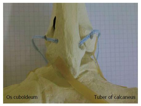
Figure 1 Lateral view on a skeletal model of a left ankle joint: Anatomic augmentation of the anterior and posterior tibiofibular ligament by use of an InternalBraceTM technique is simulated.
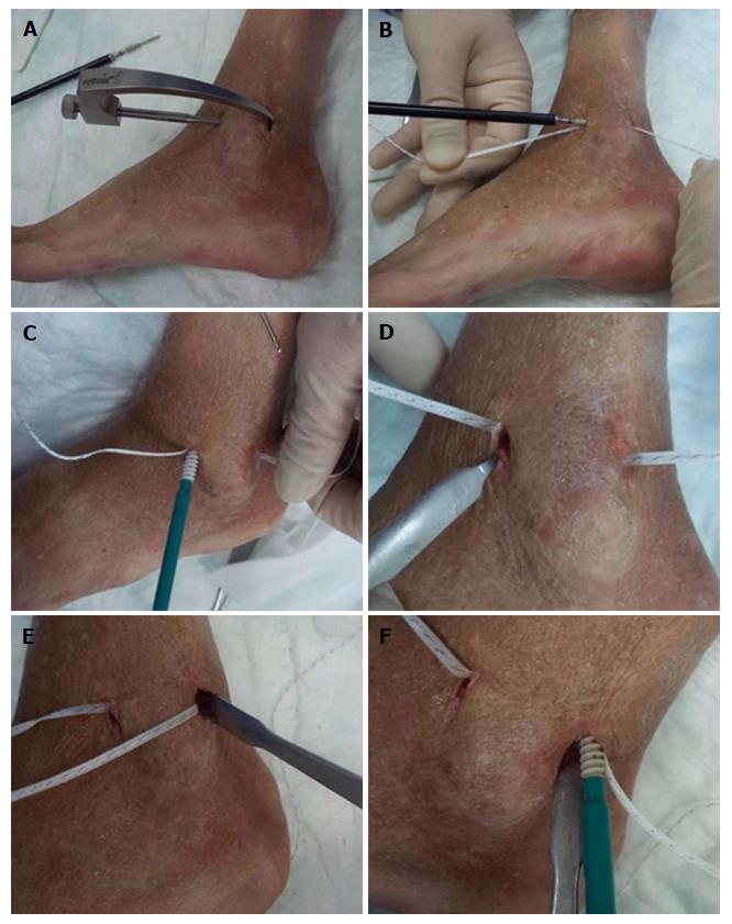
Figure 2 Minimally invasive anatomic augmentation of the anterior and posterior syndesmosis in a cadaver model (A-F).
Note: The FiberTape® has to be locked securely inside the bone tunnel of the distal fibula by use of an interference screw to avoid movements of the Tape inside the tunnel with potential sawing effects.
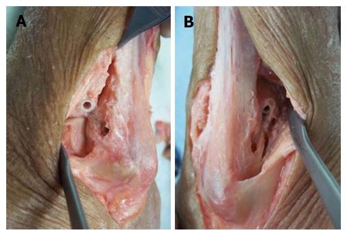
Figure 3 Control of the positioning of the implants by extensive opening of the cadaver situs.
View from anterolateral (A) and from posterolateral (B) on a left ankle joint: correct placement of the four anchors for anatomic reduction and augmentation of the anterior and posterior tibiofibular ligament.
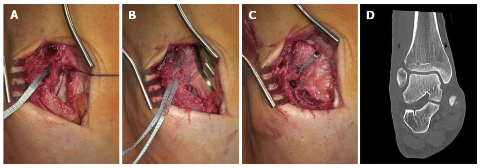
Figure 4 Syndesmotic InternalBraceTM for anterior single stabilization after suturing of the disrupted anterior syndesmotic ligament (A-D).
Figure 5 Syndesmotic InternalBraceTM for double stabilization by combination with a slightly posteriorly running TightRope® for indirect reduction (A) and stabilization (B) of the fracture of the posterior malleolus.
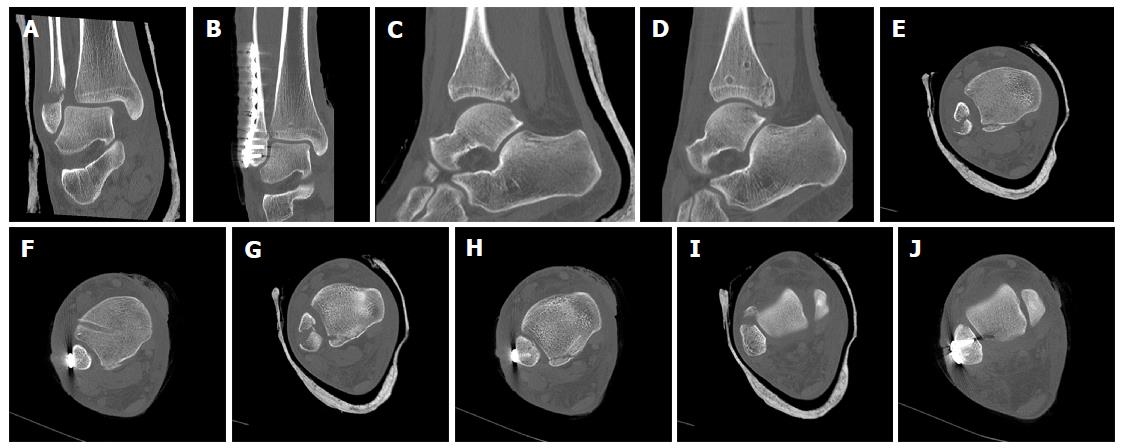
Figure 6 Syndesmotic InternalBraceTM for double stabilization.
Comparison of preoperative (A, C, E, G, I) and postoperative (B, D, F, H, J) CT scans. Note: anatomic positioning (F, H) and rotation (J) of the distal fibula and indirect anatomic reduction of the fracture of the posterior malleolus (D, F, H).
Figure 7 Syndesmotic InternalBraceTM for triple stabilization.
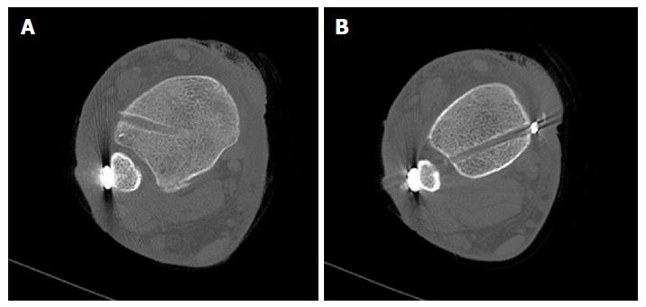
The posterior malleolus was first directly refixed with a lag screw (A), then the anterior syndesmosis was augmented with an InternalBraceTM under direct view (B, C), and finally the posterolateral screw fixation was augmented by a slightly posteriorly directed TightRope® resulting in a perfect anatomical positioning of the highly unstable distal fibula (D).
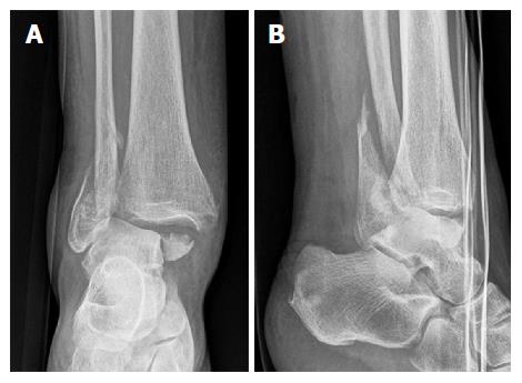
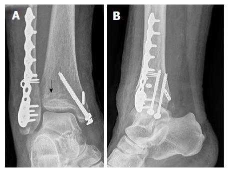
Figure 8 Trimalleolar dislocation fracture of a right ankle joint (A, B).
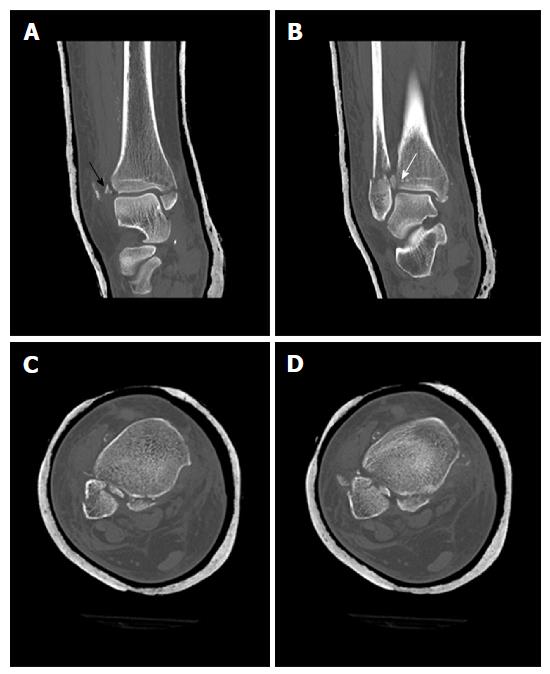
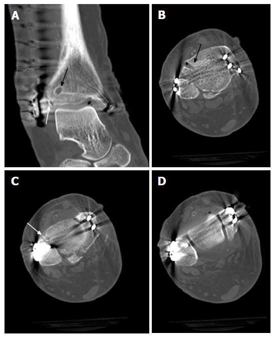
Figure 9 Computed tomography scans of the ankle from Figure 8 showing tibial avulsion of the anterior tibiofibular ligament with dislocation of a bone fragment (black arrow) too small for screw fixation (A), complete closed reduction was not possible due to a small bone fragment (white arrow) interposed between distal tibia and fibula (B), displaced avulsion of a small fragment of the posterolateral malleolus (C, D).
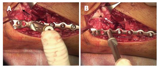
Figure 10 Surgical treatment of the patient from Figure 8.
Note the small bony tibial avulsion fragment of the anterior tibiofibular ligament (black arrow) and the corresponding avulsion site (white arrow) at the tubercule de Chaput (A). After reduction of the avulsion fragment the whole ligament proved to be intact (B). Insertion of a FiberTape® about 4 mm proximal and medial of the avulsion site with a 4.75 mm SwiveLock® (C). Standard osteosynthesis of the distal fibula was performed using an anatomic preformed locking plate (Arthrex®, Naples, United States). The reduced tibial avulsion fragment was then stabilized with a FiberTape® fixed by the tibial 4.75 mm SwiveLock® and by knots under the osteosynthesis plate (D).
Figure 11 Postoperative X-rays of the ankle from Figure 8 showing anatomic reduction of the syndesmotic injury (A, B).
The tibial bone tunnel for the InternalBraceTM visible (black arrow).
Figure 12 Postoperative computed tomography scans of the ankle from Figure 8 showing anatomic reduction of the tibial avulsion (white arrows) of the anterior tibiofibular ligament (A, C) as well as anatomic reduction of the ankle mortise (D); the tibial bone tunnel (black arrows) for the InternalBraceTM is clearly visible (A, B).
Figure 13 Intraoperative testing of syndesmotic stability after distal fibular plating: The classical hook test (A, B) shows no lateral translation of the distal fibula while pulling the distal fibula laterally and pushing the distal tibia medially, indicating a normal result without syndesmotic instability, however, the same ankle joint shows relevant rotational instability of the anterior tibiofibular ligament (C, D) indicating the need for surgical stabilization.
Figure 14 Intraoperative testing of syndesmotic stability after distal fibular plating using a mounted drill bit for locking screws: The ankle joint shows relevant external rotational instability of the anterior tibiofibular ligament (B) indicating the need for surgical stabilization.
Note opening (white arrow in B) of the star figure (black arrow in A) normally built by the tibiofibular, tibiotalar and talofibular joint lines by external rotation of the distal fibula (B).
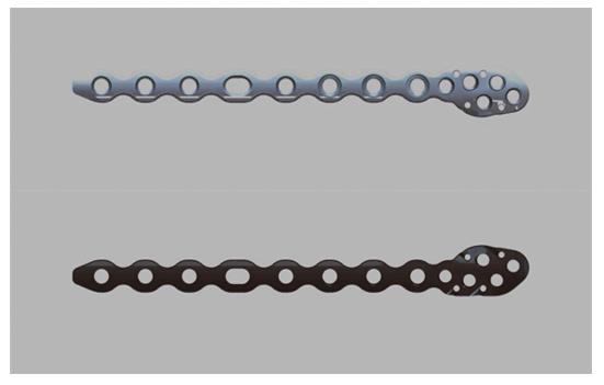
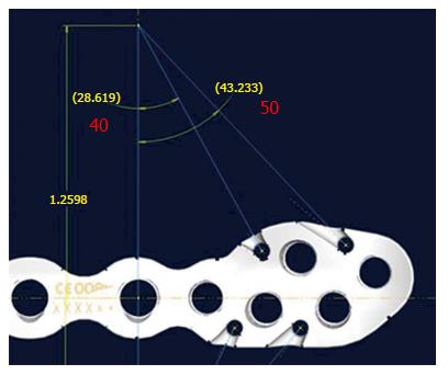
Figure 15 Prototype of a new syndesmosis plate (Arthrex, Naples, United States) with suture holes especially designed for augmentation of the anterior and posterior syndesmosis.
Figure 16 Prototype of a new syndesmosis plate with four suture holes, each combined with a specially designed notch at the inside surface exactly in line with the potential course of the inserted and tensioned FiberTape®.
- Citation: Regauer M, Mackay G, Lange M, Kammerlander C, Böcker W. Syndesmotic InternalBraceTM for anatomic distal tibiofibular ligament augmentation. World J Orthop 2017; 8(4): 301-309
- URL: https://www.wjgnet.com/2218-5836/full/v8/i4/301.htm
- DOI: https://dx.doi.org/10.5312/wjo.v8.i4.301


