Copyright
©The Author(s) 2017.
World J Orthop. Mar 18, 2017; 8(3): 221-228
Published online Mar 18, 2017. doi: 10.5312/wjo.v8.i3.221
Published online Mar 18, 2017. doi: 10.5312/wjo.v8.i3.221
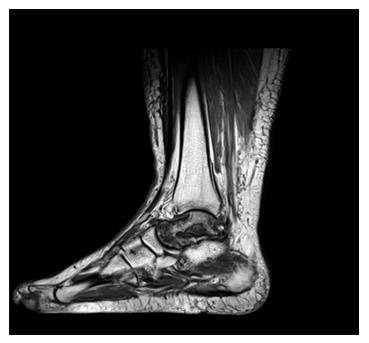
Figure 1 Magnetic resonance imaging of a 32-year-old male patient showing complete avascular necrosis of the talus.
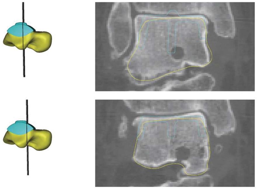
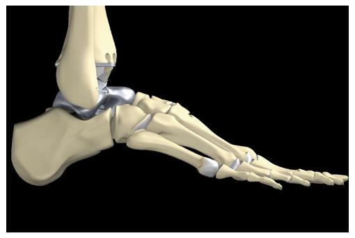
Figure 2 A customized hemiprosthesis was developed using computed tomography and magnetic resonance imaging data of the affected and contralateral talus considering the option of integrating the S.
T.A.R. prosthesis (Stryker) into the design.
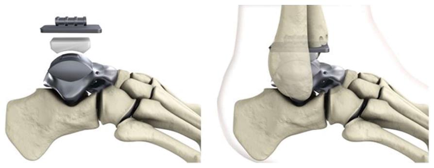
Figure 3 Components of the customized hemiprosthesis for combination with the S.
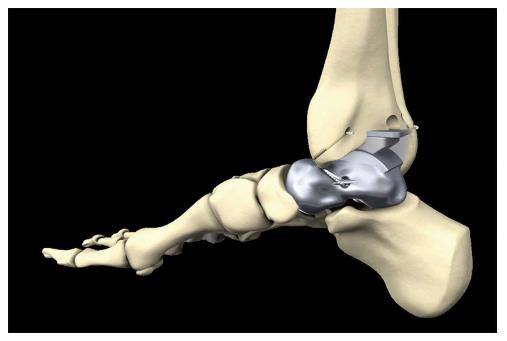
T.A.R. prosthesis (Stryker).
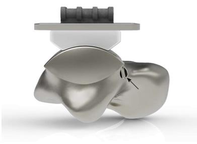
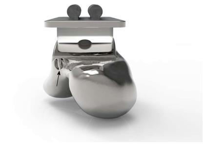
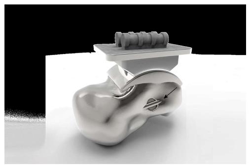
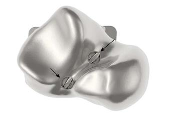
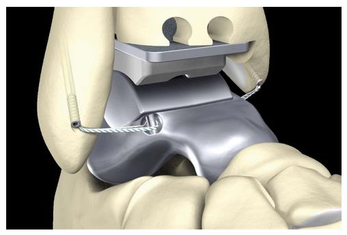
Figure 4 Eyelets for fixation of artificial ligaments (FiberTape®, Arthrex) were added at the corresponding footprints of the main ankle ligaments.
View from lateral on the eyelet (black arrow) for the artificial anterior talofibular ligament.
Figure 5 View from anterior on the eyelet (black arrow) for the artificial anterior talofibular ligament.
Figure 6 View from medial on the eyelet (black arrow) for fixation of the artificial deltoid ligament.
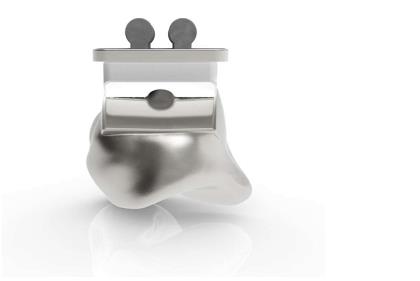
Figure 7 In the view from posterior the eyelets are not visible.
Figure 8 View from plantar on the eyelets (black arrows) for the artificial interosseous talocalcaneal ligament.
Figure 9 Anterolateral stabilization of the customized hemiprosthesis by use of an InternalBraceTM in the anatomic course of the anterior talofibular ligament viewed from lateral.
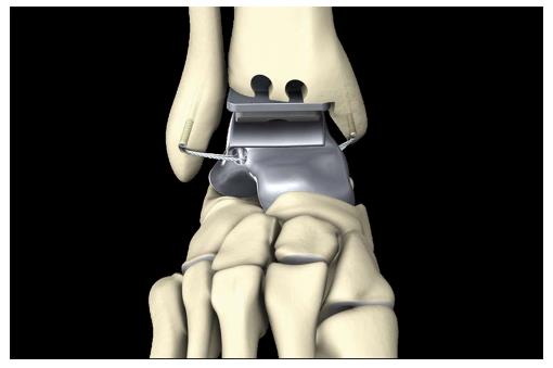
Figure 10 Anterolateral and anteromedial stabilization of the customized hemiprosthesis by use of an InternalBraceTM in the anatomic courses of the anterior talofibular ligament and the deltoid ligament viewed from anterolateral.
Figure 11 Anterolateral and anteromedial stabilization of the customized hemiprosthesis by use of an InternalBraceTM in the anatomic courses of the anterior talofibular ligament and the deltoid ligament viewed from anterior.
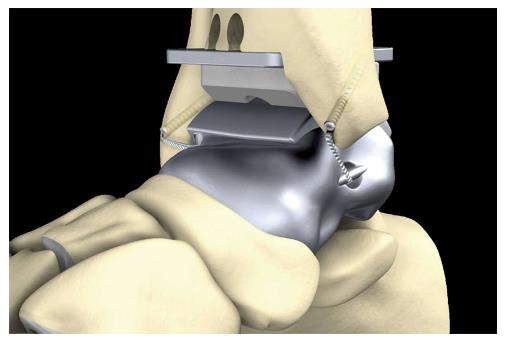
Figure 12 Anterolateral and anteromedial stabilization of the customized hemiprosthesis by use of an InternalBraceTM in the anatomic courses of the anterior talofibular ligament and the deltoid ligament viewed from anteromedial.
Figure 13 Anteromedial stabilization of the customized hemiprosthesis by use of an InternalBraceTM in the anatomic courses of the deltoid ligament viewed from posteromedial.
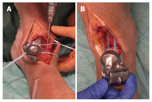
Figure 14 A feasibility study was performed using a fresh frozen male human cadaver.
A: Preparing of the bone tunnels at the anatomic footprints of the native ligaments for fixation of the artificial ligaments; B: All four artificial ligaments were shuttled through the bone tunnels before insertion of the prosthesis.
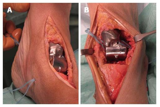
Figure 15 Prosthesis and through the bone tunnels before insertion of the prosthesis.
A: The prosthesis was inserted from anterior while steady tensioning the four artificial ligaments; B: View from anterior on the pre-tensioned anterior talofibular ligament.
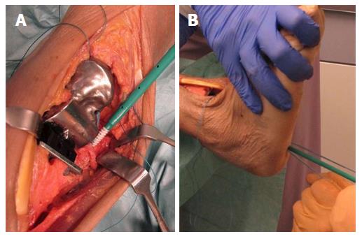
Figure 16 Aperture fixation of the correctly pre-tensioned artificial ligaments at the anatomic footprints with an interference screw (SwiveLock®4.
75 mm, Arthrex, Naples, United States). A: Direct aperture fixation of the anterior talofibular ligament at the distal fibula; B: Retrograde indirect aperture fixation of the interosseous talocalcaneal ligament at the calcaneus performed percutaneously from plantar.
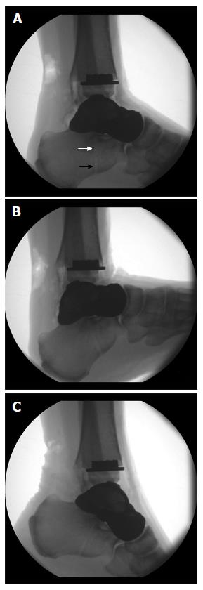
Figure 17 Radiographic examination of the maximum range of motion of the ankle joint after internally bracing of the customized hemiprosthesis.
A: Neutral position; B: Maximum dorsiflexion 22°; C: Maximum plantarflexion 28°. Note the visible bone tunnel in the calcaneus (black arrow) with the interference screw inside the proximal part of the tunnel (white arrow) to prevent tunnel widening by indirect aperture fixation at the subtalar joint performed percutaneously from plantar.
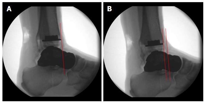
Figure 18 Maximum anterior displacement of the talus was 6 mm (B) compared to the neutral position (A).
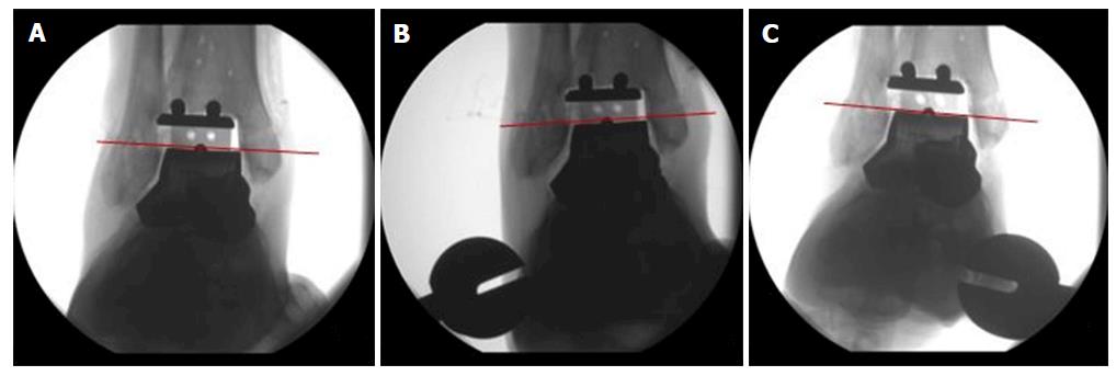
Figure 19 Compared to the neutral position (A) maximum varus tilt was 3° (B) and maximum valgus tilt was 2° (C).
- Citation: Regauer M, Lange M, Soldan K, Peyerl S, Baumbach S, Böcker W, Polzer H. Development of an internally braced prosthesis for total talus replacement. World J Orthop 2017; 8(3): 221-228
- URL: https://www.wjgnet.com/2218-5836/full/v8/i3/221.htm
- DOI: https://dx.doi.org/10.5312/wjo.v8.i3.221


