Copyright
©The Author(s) 2016.
World J Orthop. Oct 18, 2016; 7(10): 695-699
Published online Oct 18, 2016. doi: 10.5312/wjo.v7.i10.695
Published online Oct 18, 2016. doi: 10.5312/wjo.v7.i10.695
Figure 1 Case 1.
A: A magnetic resonance imaging scan image showing a dumbbell-shaped schwannoma at the C3 level; B, C: Computed tomography images showing an appropriately inserted C4 laminar screw (B) and a C6 laminar screw with minimal canal invasion (C); D: A roentgenogram showing solid bone fusion after C2-6 laminar screw fixation.
Figure 2 Case 2.
A: A magnetic resonance imaging scan image showing a Ewing’s sarcoma involving the right C7 and C8 nerve roots (arrows); B: Roentgenograms showing the laminar screws, which are placed at the C6–Th1 levels with a preoperative embolic coil in the right vertebral artery (arrows); C: A computed tomography image showing a C6 laminar screw penetrating the facet joint and a preoperative embolic coil (arrows).
Figure 3 Case 3.
A: A magnetic resonance imaging scan image showing severe cervical kyphosis with junctional canal stenosis at the C2-3 levels; B: Roentgenograms showing posterior arthrodesis performed using occipital plates, C2 pedicle screws, and laminar screws at the C3-C6 levels; C: A computed tomography image showing an appropriately inserted C3 laminar screw.
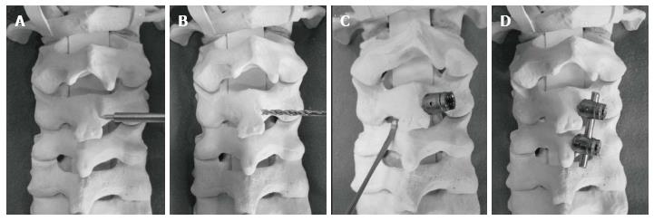
Figure 4 Surgical procedures.
A: Create a small cortical window at the junction of the C3 spinous process and the lamina on the right; B: Using a hand drill, carefully drill along the length of the contralateral (left lamina), with the drill visually aligned among the angle of the exposed contralateral laminar surface; C: Insert a 3.5 mm diameter polyaxial screw along the same trajectory in the left C3 lamina. Palpate the ventral lamina with a Penfield dissector to verify that no cortical breakthrough into the spinal canal has occurred; D: Using the same technique as above, insert a 3.5 mm diameter polyaxial screw into the left C4 lamina. Place appropriate rods into the screw heads and attach to C3 and C4 screws.
- Citation: Tanabe H, Aota Y, Saito T. Laminar screw fixation in the subaxial cervical spine: A report on three cases. World J Orthop 2016; 7(10): 695-699
- URL: https://www.wjgnet.com/2218-5836/full/v7/i10/695.htm
- DOI: https://dx.doi.org/10.5312/wjo.v7.i10.695


