Copyright
©The Author(s) 2015.
World J Orthop. Jun 18, 2015; 6(5): 421-433
Published online Jun 18, 2015. doi: 10.5312/wjo.v6.i5.421
Published online Jun 18, 2015. doi: 10.5312/wjo.v6.i5.421
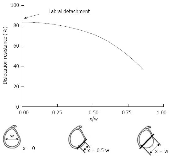
Figure 1 The graph demonstrates the relationship between the size of the glenoid rim and the dislocation risk.
When defect (×) measure more than 50% of the glenoid width there is a significant drop in dislocation resistance. Adapted with permission from Clin Orthop Related Res 2002; 400: 65-76.
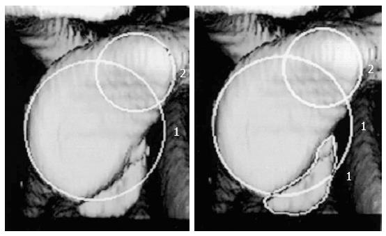
Figure 2 Using 3D reconstruction computed tomography the size o f the defect is calculated as the percentage of the on fossa glenoid.
Using circle 2 as the reference selected by the radiologist, the CT software automatically calculates the deficit by using the equation (area of the deficit/circle 1 × 100%). Adapted with permission from JBJS Am 2003; 85-A: 878-884.
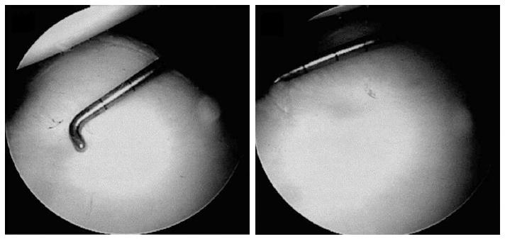
Figure 3 Through a posterior portal a 3 mm calibrate probe is inserted and the distance from the center of the bare spot to the posterior glenoid rim is measured.
Following the distance from the bare sport to the anterior glenoid rim is measured. These values are used to preform the final glenoid deficit calculation. Adapted with permission from Arthroscopy 2004; 20: 169-174.
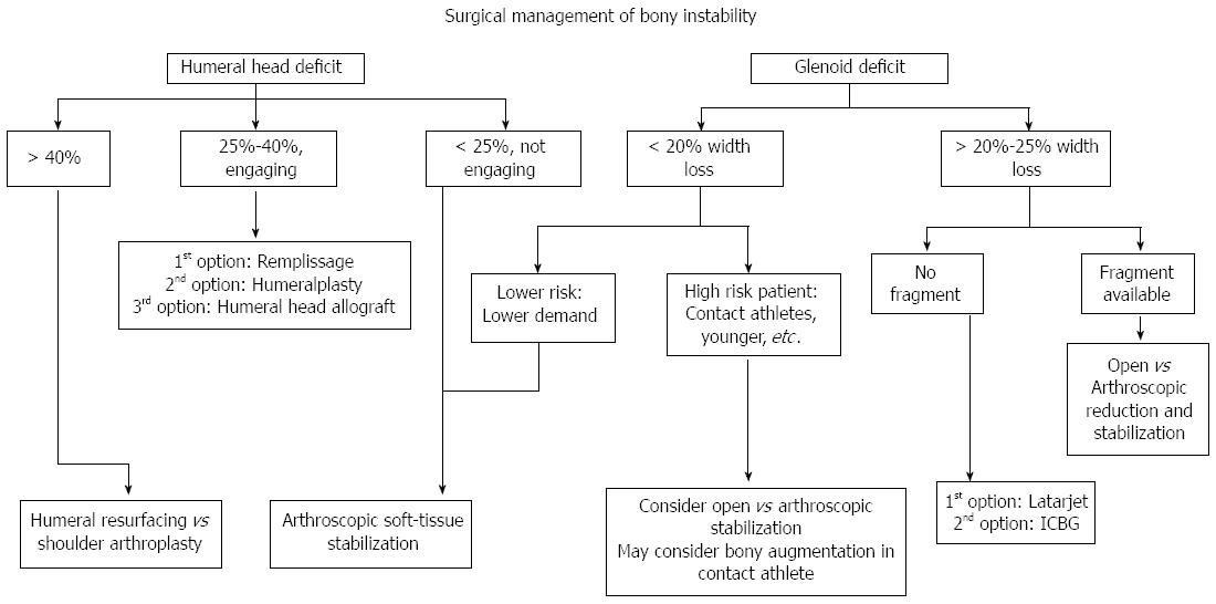
Figure 4 Our treatment algorithm of bony anterior shoulder stability.
First determination of the size of the defect is done, followed by evaluation of specific risk factors. For large glenoid defects the Latarjet procedure is preferred, while Hill-Sachs defects the remplissage is our recommended procedure.
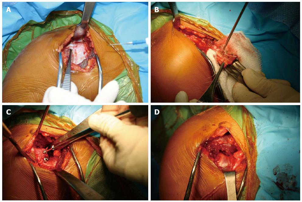
Figure 5 Intraoperative photos of the Latarjet technique.
(A) Though a deltopectoral approach the coracoid is identified (B) after osteotomizing the coracoid the entry points for the 2 screws are predrilled, and the soft tissue attachments are preserved (C) The coracoid fragment is secured with 2 partially thread screws on the anterior surface of the glenoid (D) The joint capsule is secured to the coracoid fragment with 2 sutures.
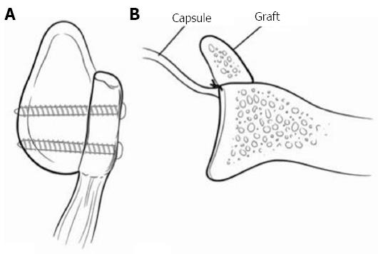
Figure 6 Represents a Latarjet procedure.
A: A sagittal view with 2 screws securing the coracoid fragment; B: The capsule is secured posterior to the graft making the construct extra-articular. Adapted with permission from J Am Acad Orthop Surg 2009; 17: 482-493.
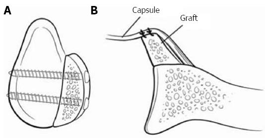
Figure 7 Represents an iliac crest autograft.
A: A sagittal view with 2 screws securing the iliac crest; B: The capsule is placed anteriorly making the construct intra-articular. The graphs natural wing is facing towards the joint to better match the glenoid previous contour. Adapted with permission from J Am Acad Orthop Surg 2009; 17: 482-493.
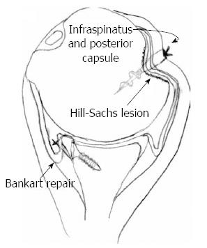
Figure 8 The remplissage technique with a suture anchor securing the infraspinatus and the posterior capsule into the Hill-Sachs defect.
In addition, a Bankart repair is performed during the procedure. Adapted with permission from Arthroscopy 2008; 24: 723-726.
- Citation: Garcia GH, Liu JN, Dines DM, Dines JS. Effect of bone loss in anterior shoulder instability. World J Orthop 2015; 6(5): 421-433
- URL: https://www.wjgnet.com/2218-5836/full/v6/i5/421.htm
- DOI: https://dx.doi.org/10.5312/wjo.v6.i5.421


