Copyright
©The Author(s) 2025.
World J Orthop. Jul 18, 2025; 16(7): 107087
Published online Jul 18, 2025. doi: 10.5312/wjo.v16.i7.107087
Published online Jul 18, 2025. doi: 10.5312/wjo.v16.i7.107087
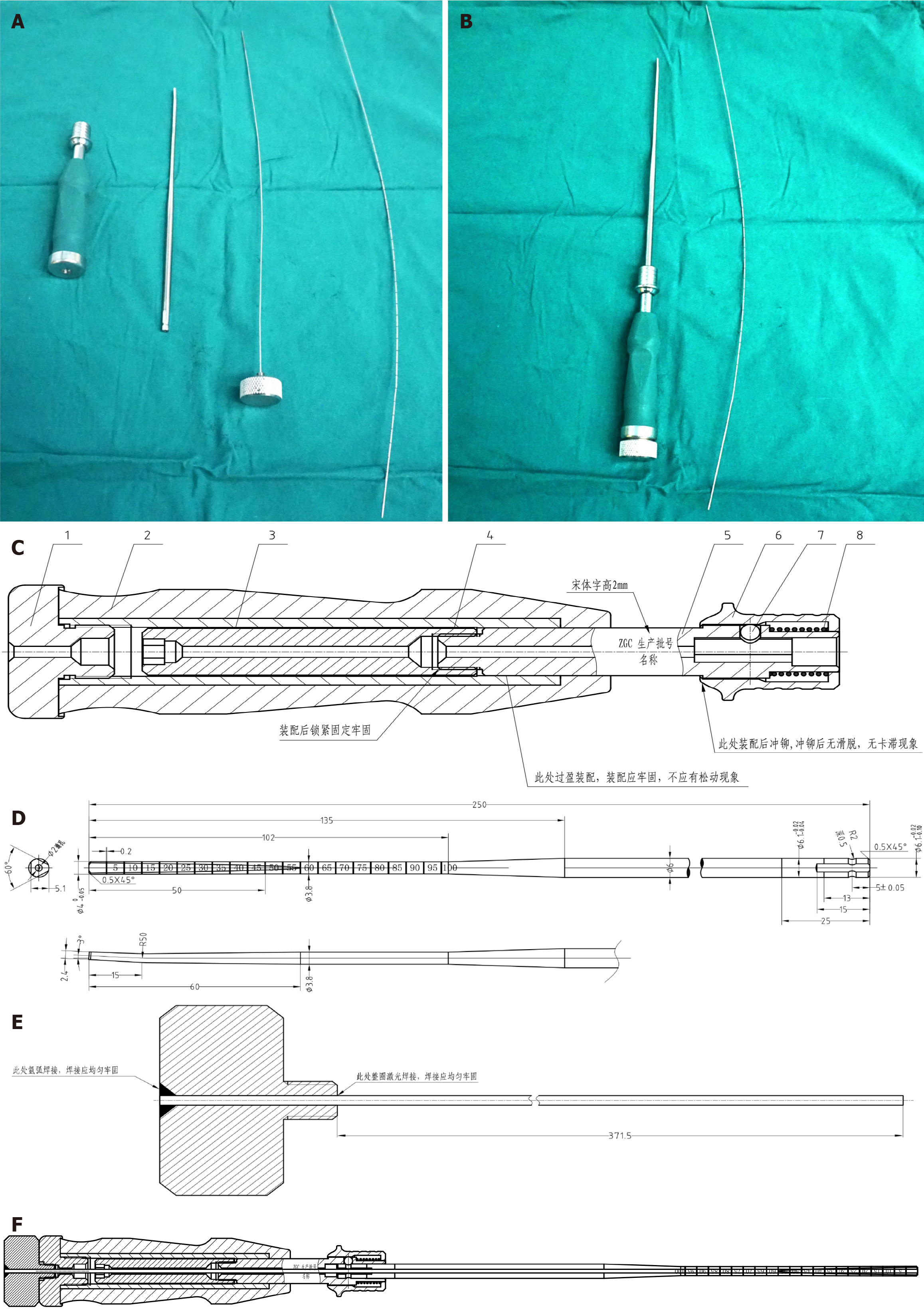
Figure 1 Design and components of the handheld pelvic alignment guide system.
A and B: Assembly diagram of the "handheld pelvic alignment guide" illustrating the complete setup of the device; C: The handle component, providing ergonomic support for the surgeon; D: The probe, used for precise alignment; E: The guiding needle, essential for accurate screw placement; F: The overall schematic, demonstrating the integrated functionality of the system.
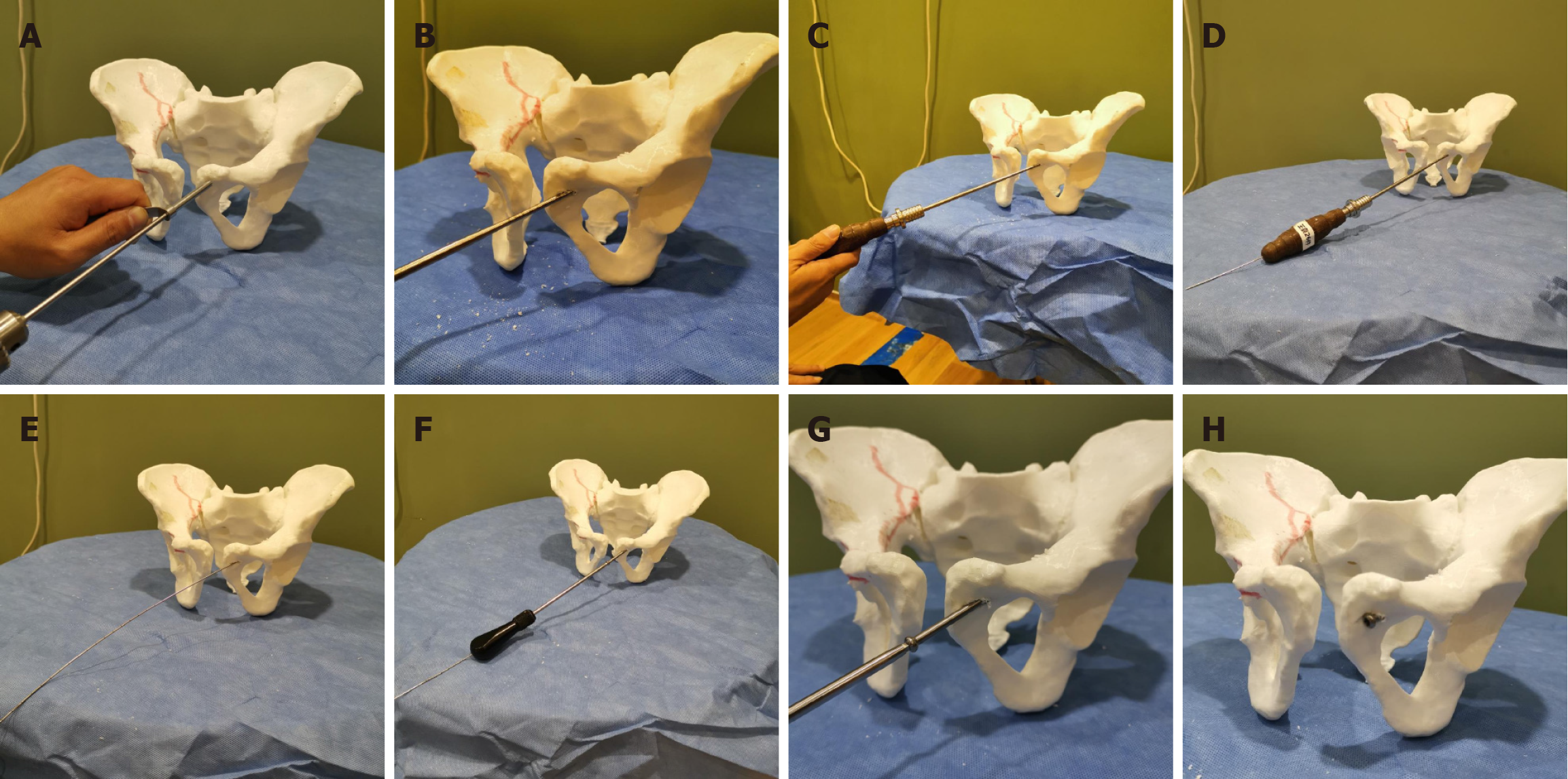
Figure 2 Simulated procedure of retrograde hollow screw insertion using the handheld pelvic alignment guide on a pelvic model.
A: The entry point is prepared using a 3.5 mm drill through the superior pubic ramus; B: The handheld pelvic alignment guide (HPAG) probe is inserted and advanced across the simulated fracture line; C: The handle is connected to the probe to maintain alignment; D: The guide pin is advanced through the central canal of the HPAG system; E: The probe remains in place, allowing for trajectory verification; F: The handle and inner core are removed, leaving the guide wire in situ; G: A hollow screw is inserted along the guide wire; H: Final position of the screw confirming proper alignment and depth.
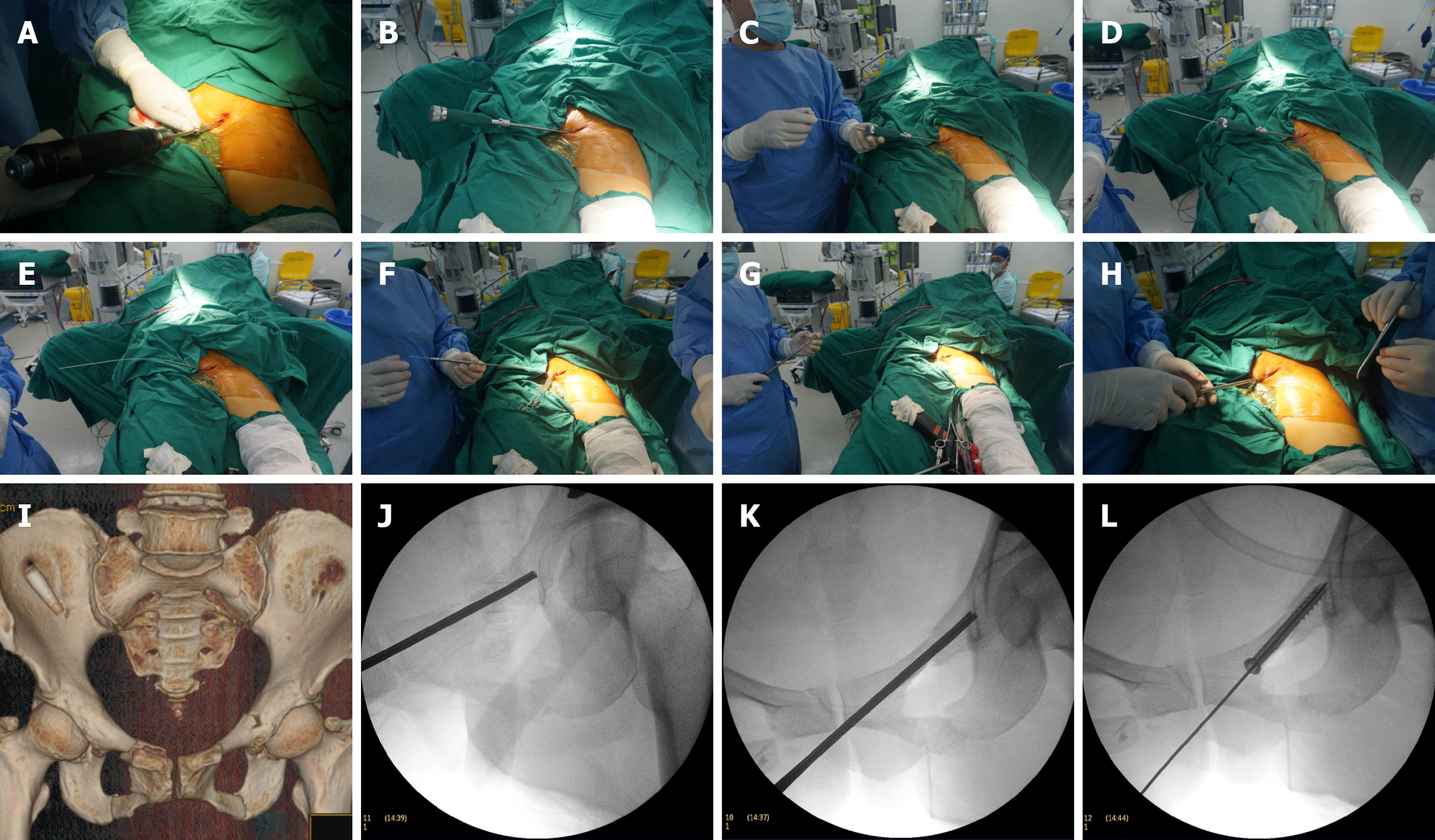
Figure 3 Intraoperative procedure of retrograde hollow screw insertion using the handheld pelvic alignment guide.
A: A 2 cm incision is made over the pubic symphysis, and a 3.5 mm drill bit is used to create an entry hole; B: The handheld pelvic alignment guide probe is inserted into the superior pubic ramus, and fracture reduction is verified under C-arm fluoroscopy; C and D: The inner core and handle are sequentially removed, and a graduated guide wire is inserted through the guide channel; E and F: Screw length is determined based on the probe's markings, and the probe is subsequently removed; G and H: A 6.0 mm hollow screw is inserted along the guide wire to complete the fixation; I: Preoperative 3D computed tomography imaging shows bilateral fractures of the superior and inferior pubic rami; J-L: Intraoperative fluoroscopy demonstrates guide wire positioning, trajectory verification, and screw insertion.
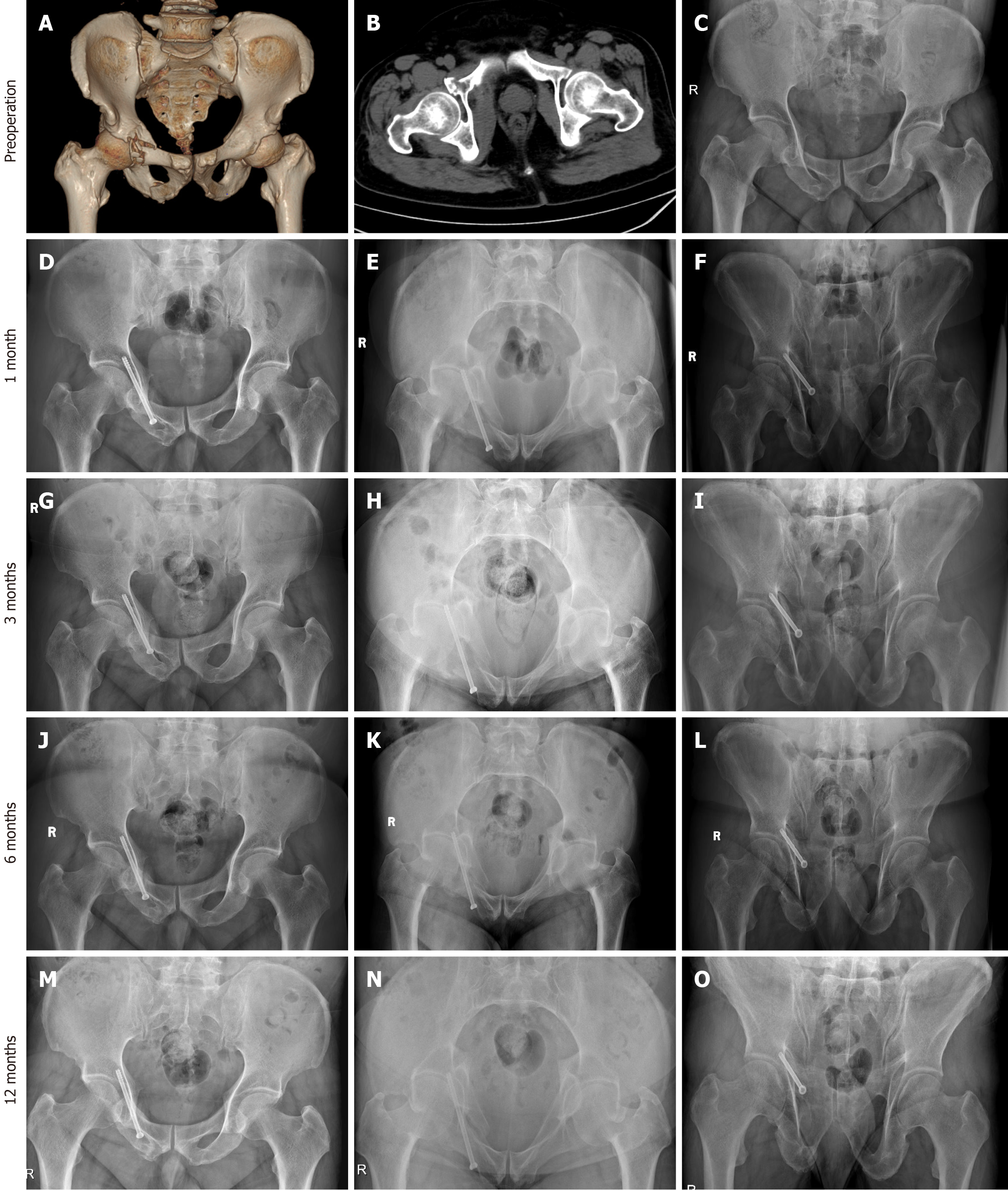
Figure 4 Radiographic follow-up of a representative patient at different postoperative timepoints.
A-C: Preoperative X-ray and 3D computed tomography images showing right pubic rami fractures; D-F: One-month postoperative radiographs demonstrating early callus formation; G-I: Three-month follow-up images indicating progressive fracture healing and callus consolidation; J-L: Six-month radiographs showing advanced callus remodeling; M-O: One-year follow-up radiographs confirming complete bony union with proper alignment.
- Citation: Wang Y, Tan ZY, He JM, Shu YX, Pan Z, Zhu DG, Wang J. Novel handheld pelvic alignment guide for hollow screw fixation in osteoporotic pelvic fragility fractures. World J Orthop 2025; 16(7): 107087
- URL: https://www.wjgnet.com/2218-5836/full/v16/i7/107087.htm
- DOI: https://dx.doi.org/10.5312/wjo.v16.i7.107087


