Copyright
©The Author(s) 2025.
World J Orthop. Jan 18, 2025; 16(1): 98871
Published online Jan 18, 2025. doi: 10.5312/wjo.v16.i1.98871
Published online Jan 18, 2025. doi: 10.5312/wjo.v16.i1.98871
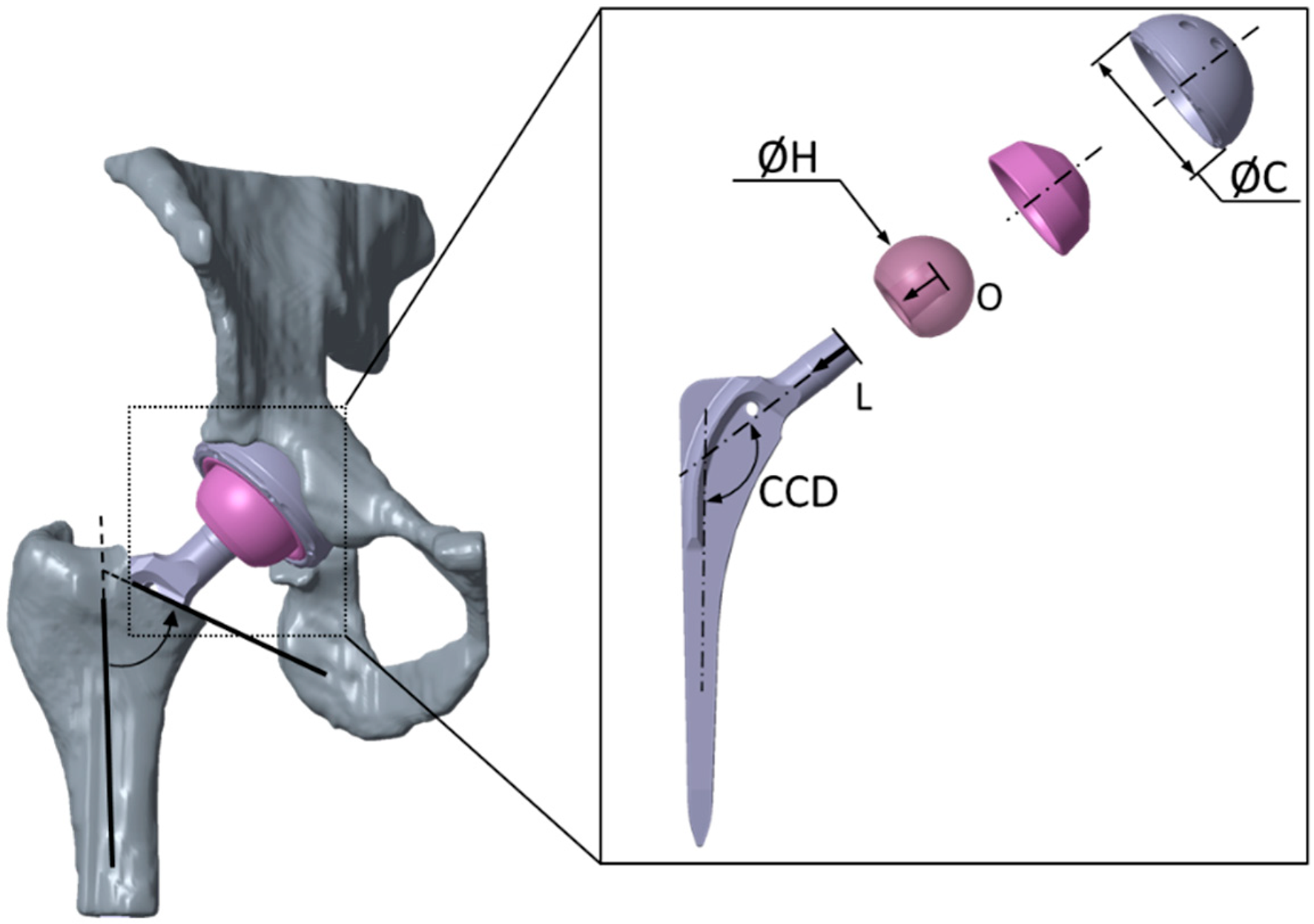
Figure 1 Total hip arthroplasty[6].
Citation: Kebbach M, Schulze C, Meyenburg C, Kluess D, Sungu M, Hartmann A, Günther K, Bader R. An MRI-Based Patient-Specific Computational Framework for the Calculation of Range of Motion of Total Hip Replacements. Appl Sci 2021; 11: 2852. Copyright ©The Author(s) 2021. Published by MDPI. CCD: Centrum-collum-diaphyseal.
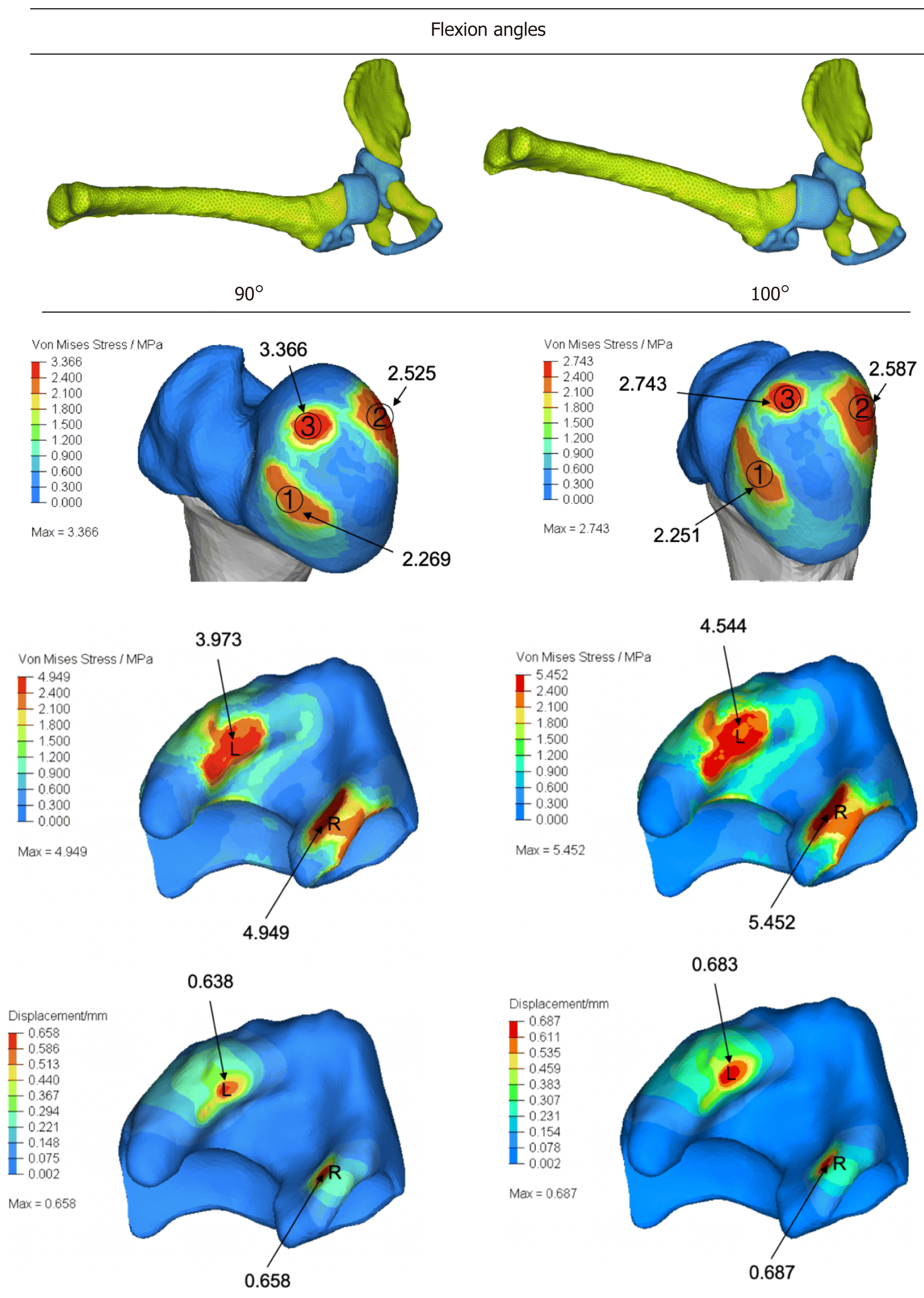
Figure 2 Von Mises stress and displacement at hip joint[23].
Citation: Zhang Z, Sui D, Qin H, Li H, Zhang Z. Contact pressure distribution of the hip joint during closed reduction of developmental dysplasia of the hip: A patient-specific finite element analysis. BMC Musculoskelet Disord 2020; 21: 600. Copyright ©The Author(s) 2020. Published by BioMed Central.
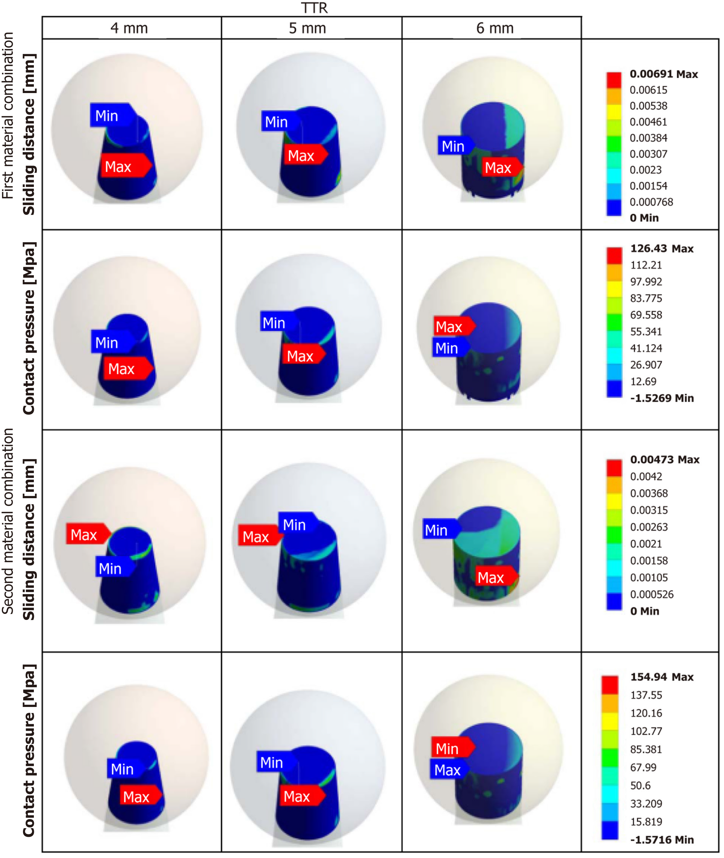
Figure 3 Contact pressure and sliding distance distribution on modified trunnion geometry of total hip arthroplasty[24].
Citation: Gutmann C, Shaikh N, Shenoy BS, Shaymasunder Bhat N, Keni LG, K N C. Wear estimation of hip implants with varying chamfer geometry at the trunnion junction: a finite element analysis. Biomed Phys Eng Express 2023; 9. Copyright ©Institute of Physics (the “Institute”) and IOP Publishing Limited. Published by IOP Publishing Limited. Max: Maximum; Min: Minimum; TTR: Taper trunnion radius.
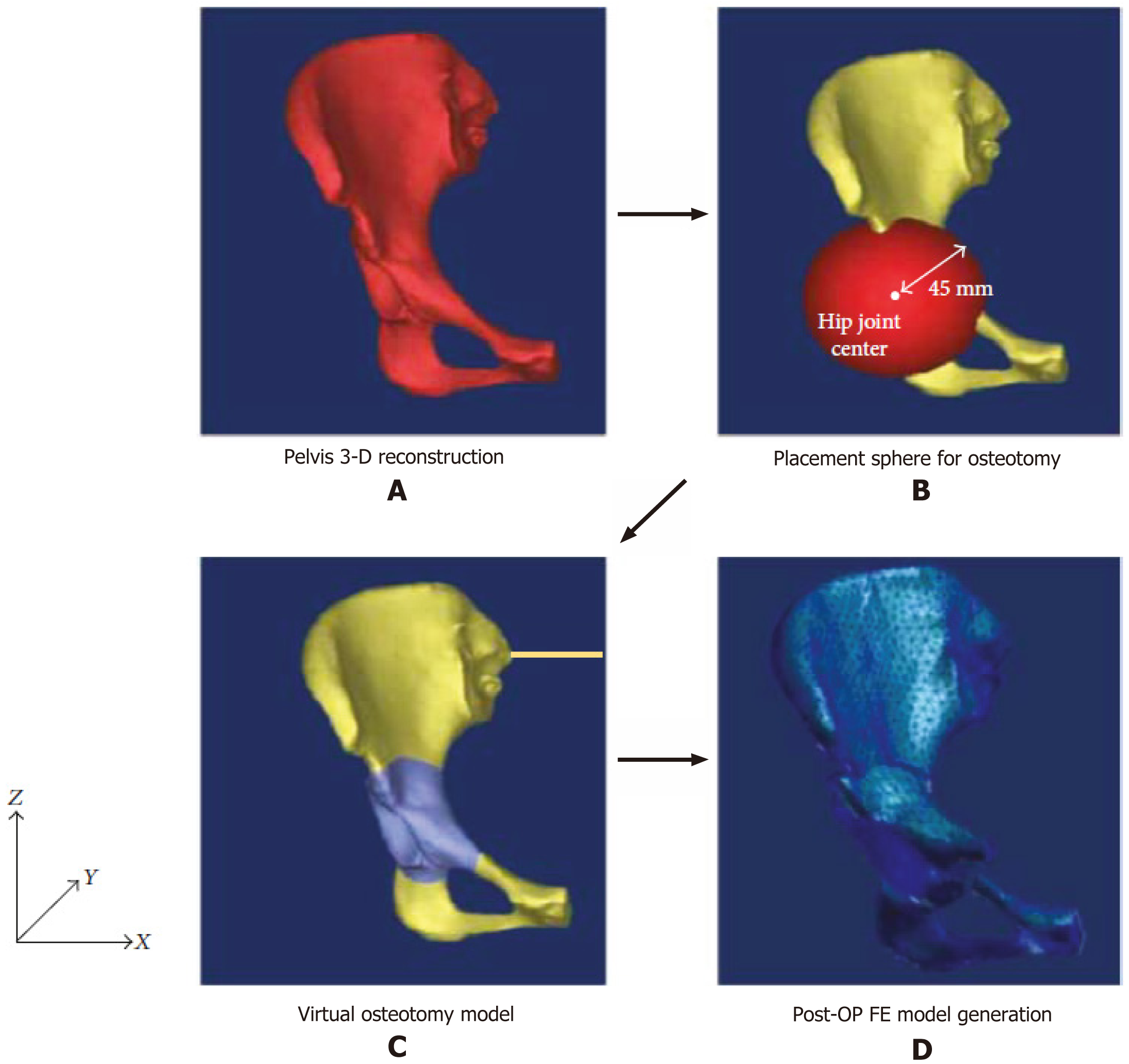
Figure 4 Finite element model using patient’s anatomy-specific[29].
Citation: Park SJ, Lee SJ, Chen WM, Park JH, Cho YS, Shin T, Kwon SY. Computer-Assisted Optimization of the Acetabular Rotation in Periacetabular Osteotomy Using Patient’s Anatomy-Specific Finite Element Analysis. Appl Bionics Biomech 2018; 2018: 9730525. Copyright ©The Author(s) 2018. Published by Hindawi Publishing Corporation. A: Pelvis 3-D reconstruction; B: Placement sphere for osteotomy; C: Virtual osteotomy model; D: Postoperative finite element model generation. Post-OP FE: Postoperative finite element.
- Citation: Ammarullah MI. Integrating finite element analysis in total hip arthroplasty for childhood hip disorders: Enhancing precision and outcomes. World J Orthop 2025; 16(1): 98871
- URL: https://www.wjgnet.com/2218-5836/full/v16/i1/98871.htm
- DOI: https://dx.doi.org/10.5312/wjo.v16.i1.98871


