Copyright
©The Author(s) 2024.
World J Orthop. Oct 18, 2024; 15(10): 965-972
Published online Oct 18, 2024. doi: 10.5312/wjo.v15.i10.965
Published online Oct 18, 2024. doi: 10.5312/wjo.v15.i10.965
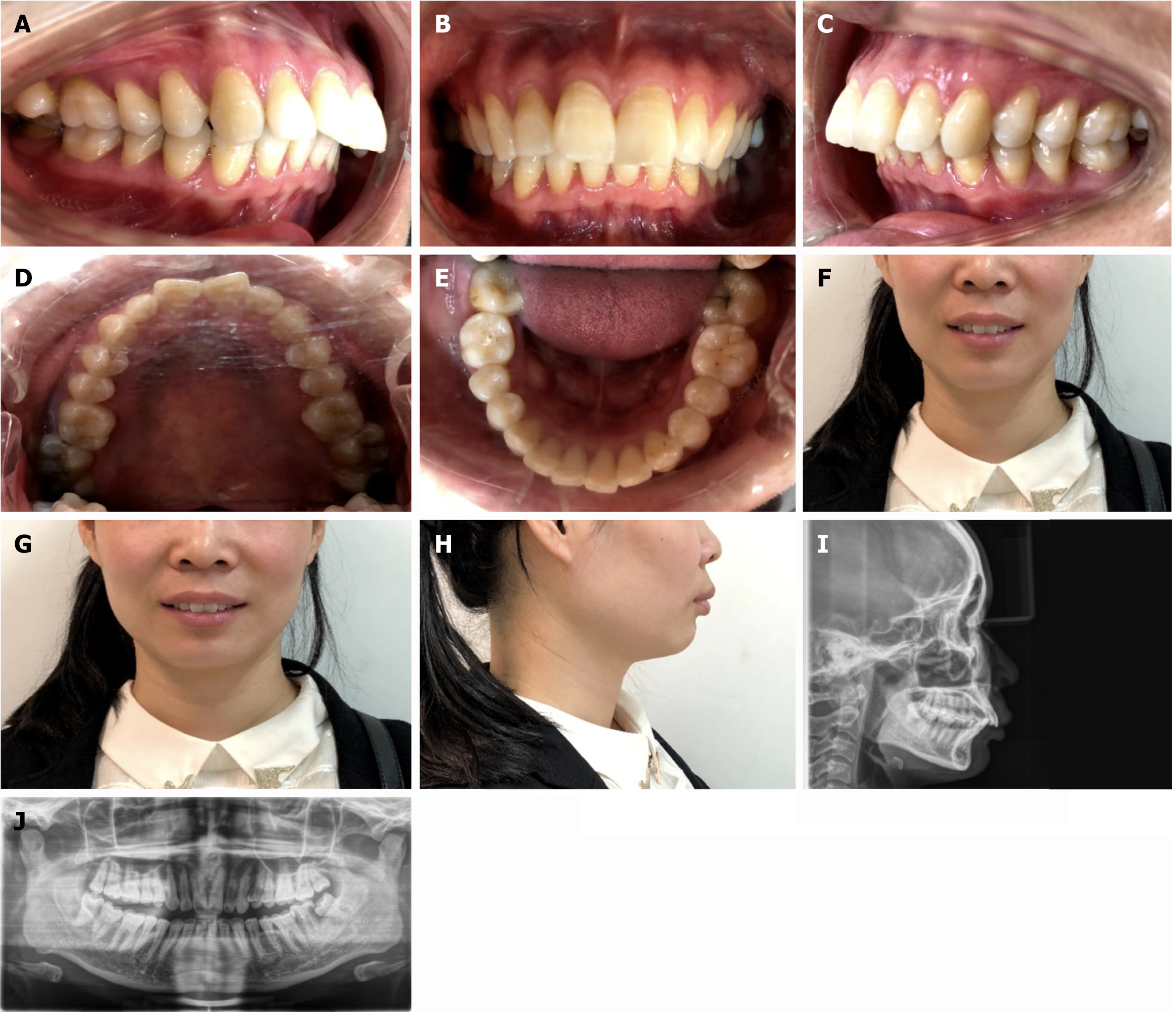
Figure 1 Pretreatment intraoral and facial photographs and panoramic radiographs.
A: The right lateral view and the scissors bite of the second permanent molars; B: The frontal view and deep overjet; C: The left lateral view and the scissors bite of the second permanent molar; D: The palatal view; E: The lingual view; F: Frontal image; G: Smiling image; H: Profile image; I: Cephalometric; J: Panoramic radiograph.
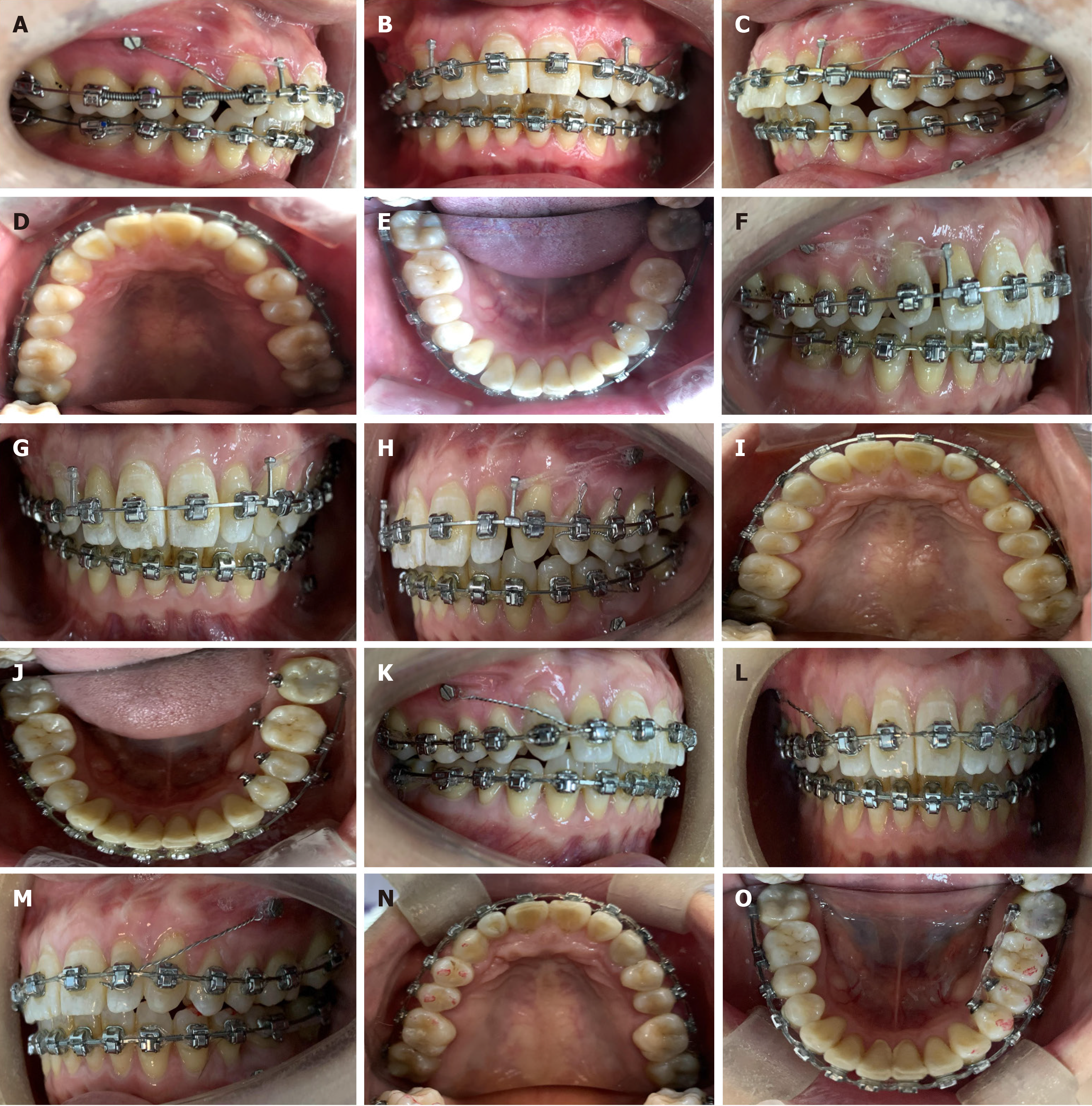
Figure 2 Photographs during the treatment process.
A: The scissors bite of the posterior teeth was released. On the 0018 × 0.025 stainless steel edgewise, springs were implanted in the mesial region of the maxillary first permanent molar and the mesial region of the maxillary first premolar, and long traction hooks were placed in the mesial region of the maxillary canine so that the force could be transmitted via traction with the microimplant nails; B: Frontal view of distal movement of maxillary dentition; C: The left lateral view of distal movement of maxillary dentition; D: The palatal view of distal movement of maxillary dentition; E: The lingual view of distal movement of maxillary dentition; F: The occlusal relationship between molars has reached Class I, and the interdental spaces obtained via distal movement of the maxillary dentition appeared in the mesial region of the canine, which was closed by bilateral sliding. The left lower third molar was upright and moved mesially; G: Frontal view of distal movement of maxillary dentition; H: The left lateral view of distal movement of maxillary dentition; I: The palatal view of distal movement of maxillary dentition; J: The lingual view of distal movement of maxillary dentition; K: The interdental spaces of the maxillary dentition were closed; L: Frontal view; M: The left lateral view; N: The palatal view; O: Moving the mandibular third molar forward to replace the second molar.
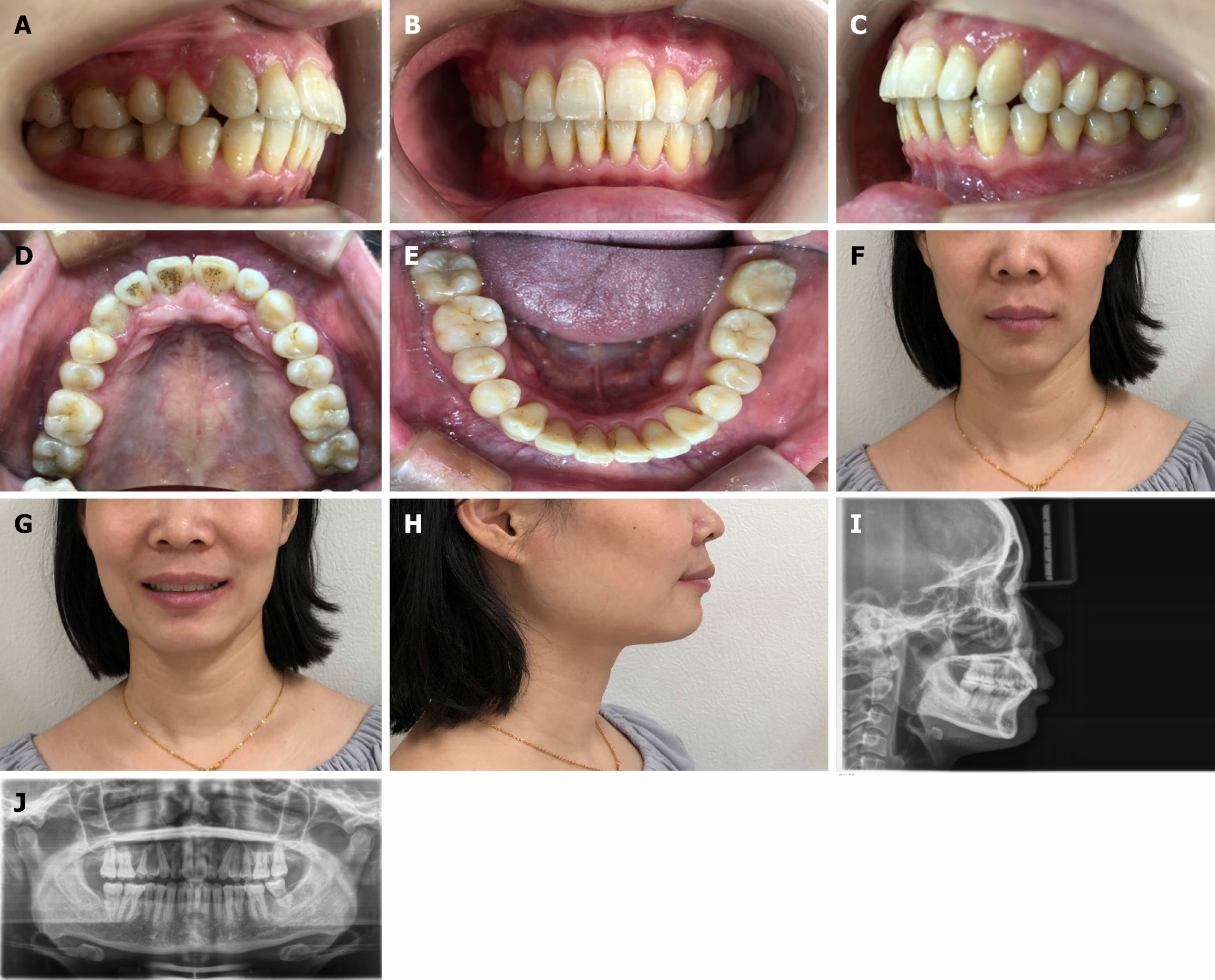
Figure 3 Posttreatment facial and intraoral photographs and panoramic radiographs.
A: The right lateral view and neutral molar relationship; B: The frontal view and normal overjet; C: The left lateral view; D: The palatal view; E: The lingual view; F: Frontal image; G: Smiling image; H: Profile image; I: Cephalometric; J: Panoramic radiograph.
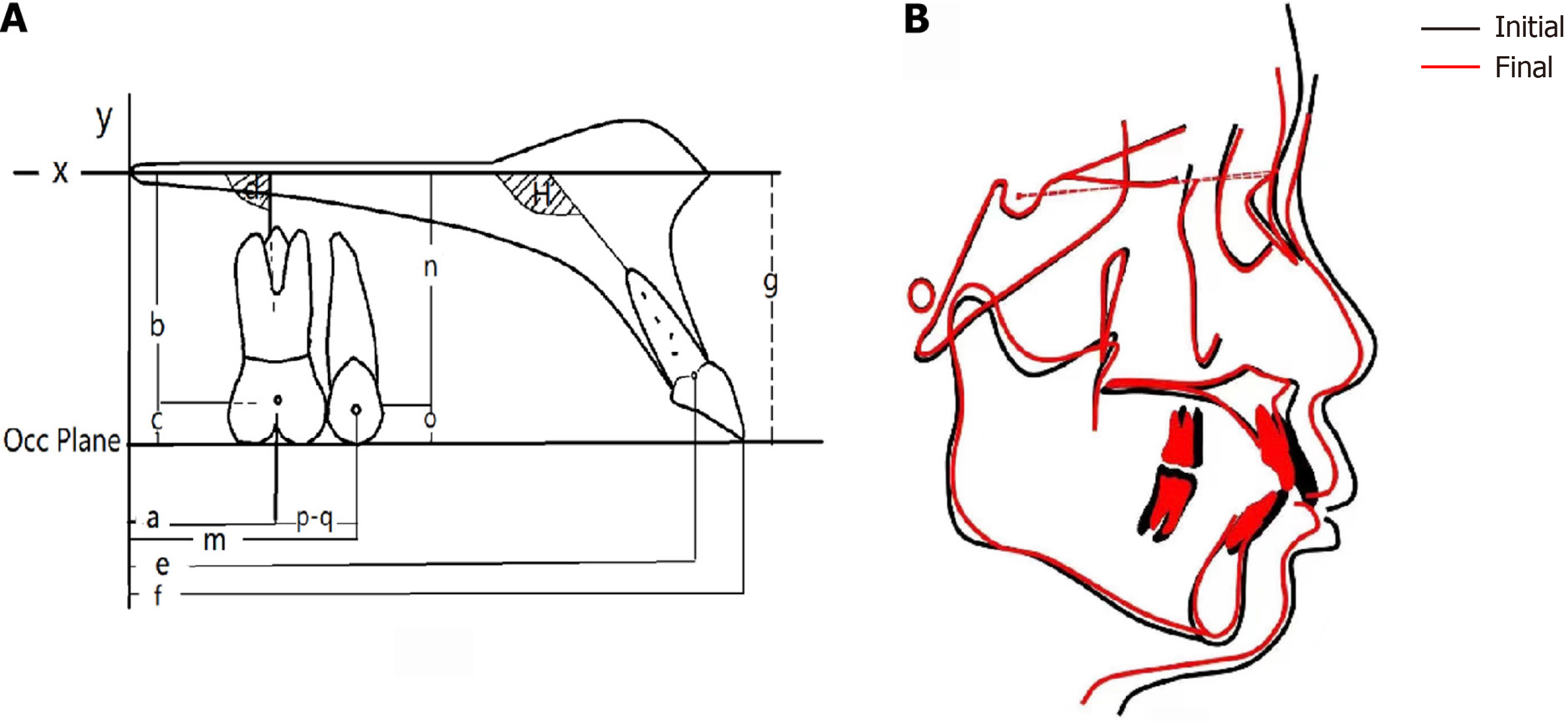
Figure 4 Cephalometric tracings and measurement indicators before and after orthodontic treatment.
A: Tooth movement measurement. The palate plane was set as the X-axis, and the vertical line from the Pt point to the palate plane was taken as the Y-axis. The incisal edge to the U6 mesiobuccal tip was the occlusal plane. a: Distance from the center point of the U6 crown to the Y-axis; b: Distance from the center point of the U6 crown to the X-axis; c: Distance between the center point of the U6 crown and the occlusal plane; d: Angle between the U6 major axis and the X-axis. e: Distance between the U1 reference point and the Y-axis. f: Distance between the U1 incisal edge point and the Y-axis. g: Distance between the U1 incisal edge point and the X-axis. h: Incisor inclination. B: Comparison of pretreatment (black line) and posttreatment (red line) cephalometric tracings.
- Citation: Xie LL, Chu DY, Wu XF. Simple and effective method for treating severe adult skeletal class II malocclusion: A case report. World J Orthop 2024; 15(10): 965-972
- URL: https://www.wjgnet.com/2218-5836/full/v15/i10/965.htm
- DOI: https://dx.doi.org/10.5312/wjo.v15.i10.965


