Copyright
©The Author(s) 2023.
World J Orthop. Aug 18, 2023; 14(8): 651-661
Published online Aug 18, 2023. doi: 10.5312/wjo.v14.i8.651
Published online Aug 18, 2023. doi: 10.5312/wjo.v14.i8.651
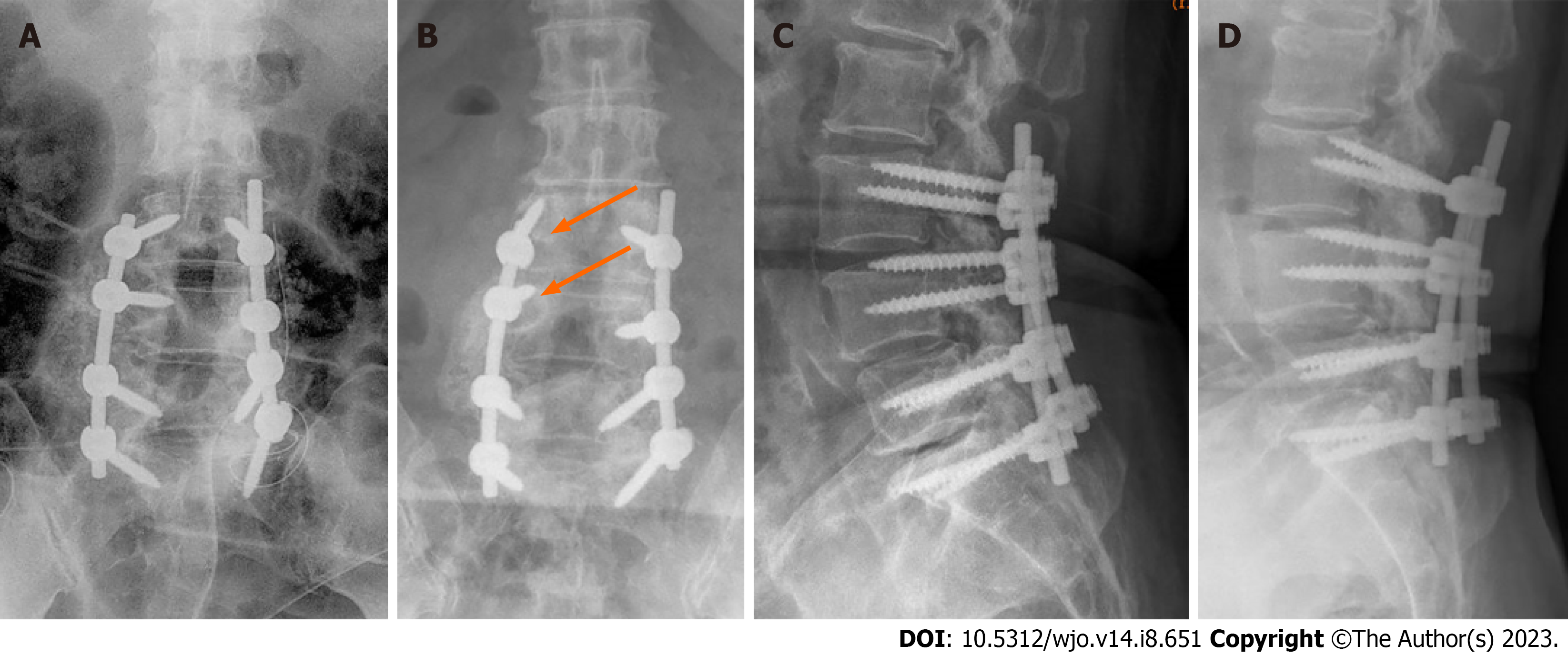
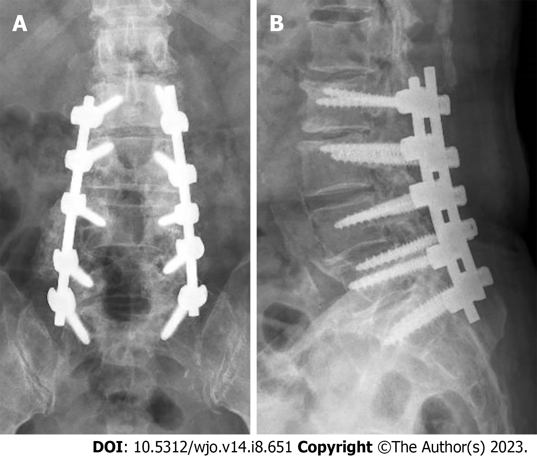
Figure 1 Postoperative lumbar spine radiographs showing the proper positioning of the spinal implants.
A: Lumbar spine antero-posterior radiograph after initial surgery for posterior decompression and instrumented fusion; B: Lumbar spine antero-posterior radiograph at 5 years after initial surgery, showing stable periprosthetic radiolucencies (indicated by arrows) surrounding the right L3 and L4 screws suggestive of instrumentation loosening; C: Lumbar spine lateral radiograph after initial surgery; D: Lumbar spine lateral radiograph at 5 years after initial surgery.
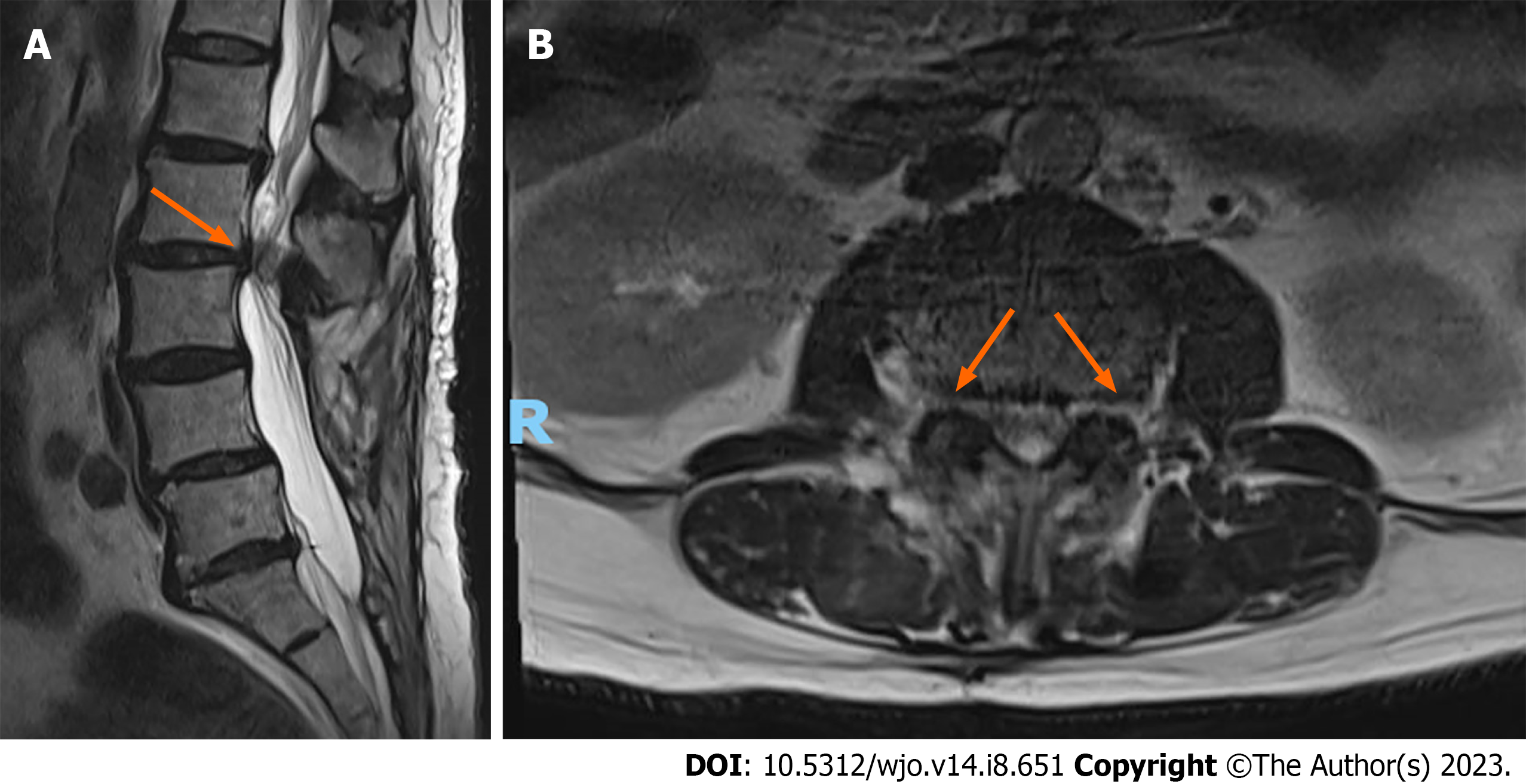
Figure 2 Lumbar spine magnetic resonance imaging (T2 weighted) 5 years after initial surgery.
A: Sagittal view. The arrow indicates herniated disc at L2-L3 level with severe spinal canal stenosis and compression of the cauda equina nerve roots; B: Coronal view demonstrating severe spinal cord compression at L2-L3 level. Arrows indicate protruded disc with bilateral lateral recess and neural foramina stenosis.
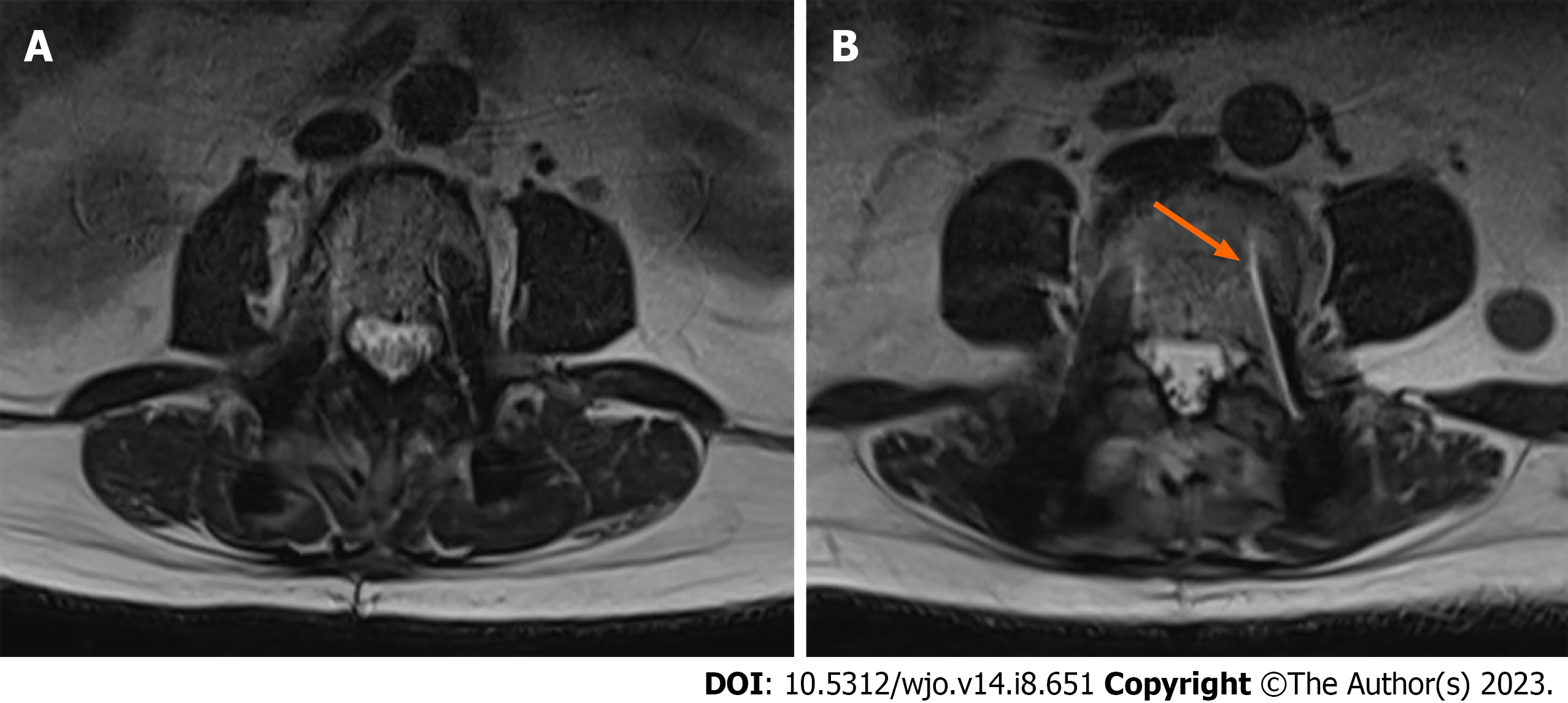
Figure 3 Lumbar spine magnetic resonance imaging (T2 weighted) 5 years after initial surgery.
A: Coronal view showing L3 level with no significant peri-screw bony edema; B: Coronal view showing L4 level with the arrow indicating mild left L4 peri-screw bony edema.
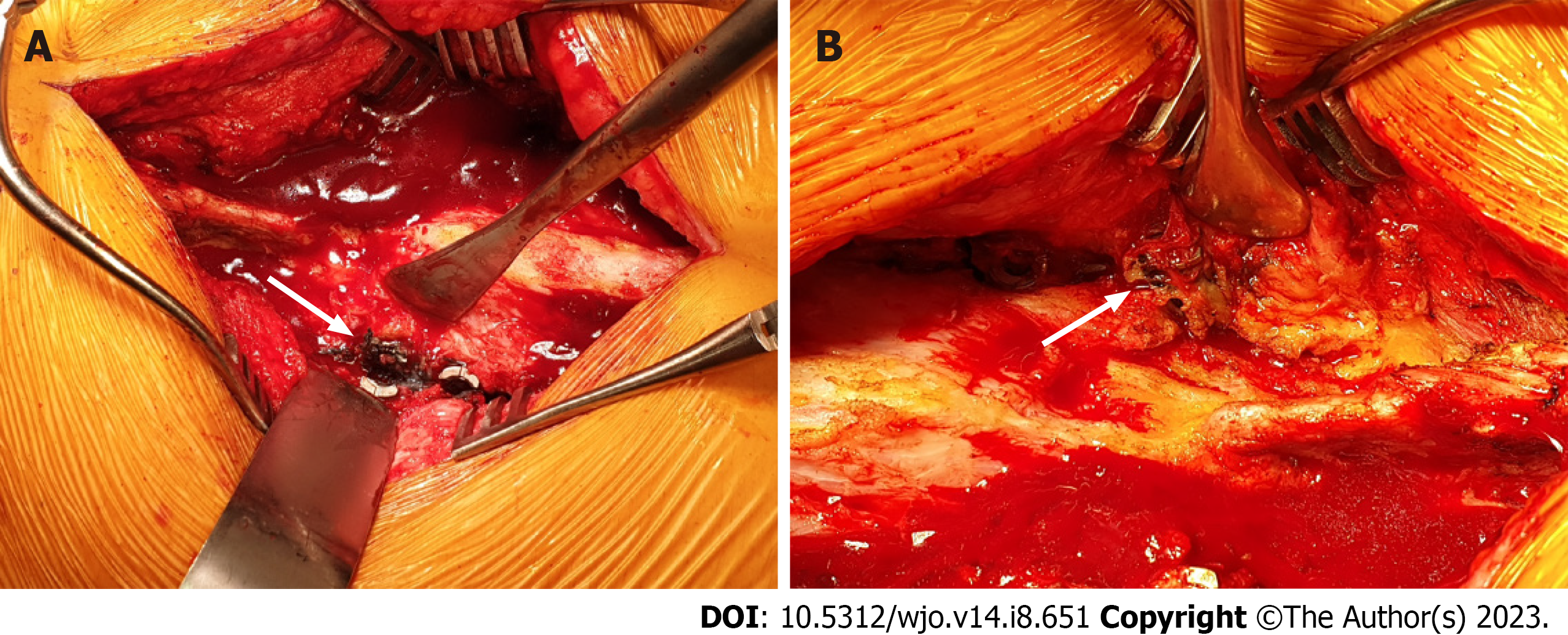
Figure 4 Intraoperative photographs during revision surgery showing metallic grey-stained tissue surrounding bilateral L3 to L5 polyaxial screw heads.
The most prominent staining occurred at A: Left L4 screw (indicated by the arrow); B: Right L4 screw (indicated by the arrow).
Figure 5
Lumbar spine antero-posterior and lateral radiographs showing proper positioning of the implants after revision L2-S1 surgery.
- Citation: Kwan YH, Teo HLT, Dinesh SK, Loo WL. Metallosis with spinal implant loosening after spinal instrumentation: A case report. World J Orthop 2023; 14(8): 651-661
- URL: https://www.wjgnet.com/2218-5836/full/v14/i8/651.htm
- DOI: https://dx.doi.org/10.5312/wjo.v14.i8.651


