Copyright
©2014 Baishideng Publishing Group Inc.
World J Clin Oncol. Dec 10, 2014; 5(5): 824-844
Published online Dec 10, 2014. doi: 10.5306/wjco.v5.i5.824
Published online Dec 10, 2014. doi: 10.5306/wjco.v5.i5.824
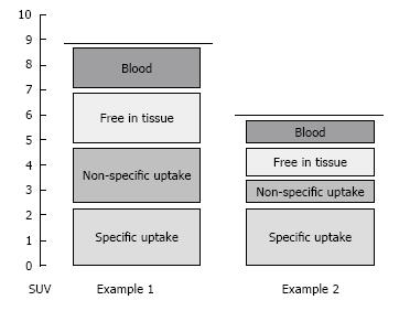
Figure 1 Graphical representation of the different components that determine the total positron emission tomography signal.
Examples 1 and 2 can represent either different patients, different lesions in one patient or different scans of one patient, for example before and after therapy. In both examples the contributions of specific uptake (the uptake of interest) are equal, but the total signal is different due to differences in contribution of other (non-relevant) signals. Measured standardized uptake value (SUV) values are reflected by the dashed lines. As SUV does not only reflect the specific signal, its use should be validated before it is used in a clinical setting, i.e., it is required to assess if contributions from non-specific signals affect SUV values in a non-predictable way. For the purpose of illustration, the Y-axis represents SUV values on an arbitrarily chosen scale.
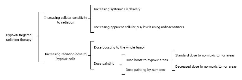
Figure 2 Radiation therapy treatment strategies for tumor hypoxia.
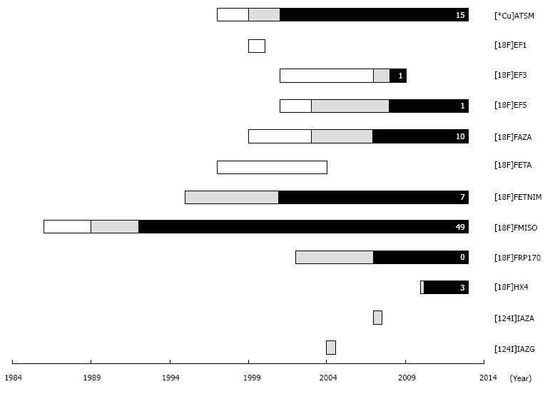
Figure 3 Timeline for development and evaluation of hypoxia specific tracers that have been evaluated by preclinical or clinical positron emission tomography.
Development and in-vitro analysis (blank), preclinical positron emission tomography (PET) evaluation (grey), and clinical PET evaluation (black). The number of published clinical studies in oncology is indicated (excluding brain studies). See Table 2 for full names.
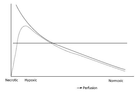
Figure 4 Representation of hypothetical considerations on the link between perfusion and the hypoxia signal as measured by imaging positron emission tomography.
The continuous curve represents hypothetical level of hypoxia in tissue for increasing levels of perfusion (i.e., closer to the capillaries). The dotted line represents the positron emission tomography signal obtained from hypoxia imaging using an optimal imaging protocol. The horizontal line represents a threshold used for delineation of hypoxic areas.
Figure 5 Example of consecutive perfusion and hypoxia positron emission tomography in a patient with non-small cell lung cancer.
A: Low dose computed tomography; B: Perfusion image (averaged image acquired over time interval 30-120 s after injection of 370 MBq [15O]H2O); C: Hypoxia image (averaged image over time interval 40-70 min after injection of 185 MBq [18F]FAZA).
- Citation: Verwer EE, Boellaard R, Veldt AAVD. Positron emission tomography to assess hypoxia and perfusion in lung cancer. World J Clin Oncol 2014; 5(5): 824-844
- URL: https://www.wjgnet.com/2218-4333/full/v5/i5/824.htm
- DOI: https://dx.doi.org/10.5306/wjco.v5.i5.824


