Copyright
©2014 Baishideng Publishing Group Inc.
World J Clin Oncol. Oct 10, 2014; 5(4): 764-774
Published online Oct 10, 2014. doi: 10.5306/wjco.v5.i4.764
Published online Oct 10, 2014. doi: 10.5306/wjco.v5.i4.764
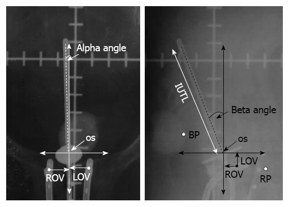
Figure 1 Schematic representation of antero-posterior and lateral radiographs with the applicator for estimation of various applicator components.
IUTL: Intrauterine length; VDL: Vertical displacement; ADL: Antero-posterior displacement; ROV: Right ovoid to os; LOV: Left ovoid to os LOV; BP: ICRU bladder point; RP: ICRU rectal point; ICRU: International Commission on Radiation Units and Measurements. Reproduced with permission[18].
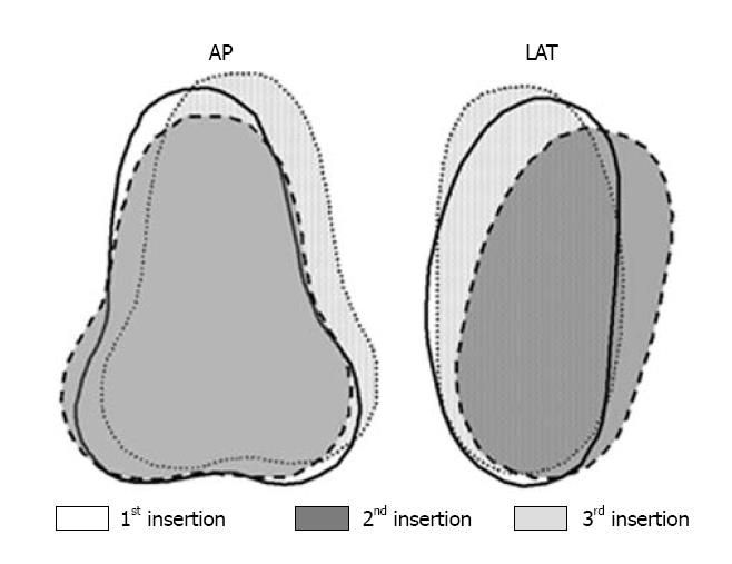
Figure 2 Fusion of standard Fletcher-Suit application positions of three insertions in a given patient with respect to the bony pelvis depicted in antero-posterior and lateral projections.
Reproduced with permission[21]. LAT: Lateral; AP: Antero-posterior.
Figure 3 Fusion of three 6 Gy International Commission on Radiation Units and Measurements 38 dose distribution in a given patient with respect to the cervical os depicted in antero-posterior and lateral projections.
Reproduced with permission[21].
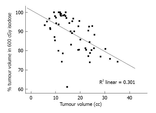
Figure 4 Scatter-plot for tumour volume vs percentage of tumour enclosed within the 6 Gy isodose lines.
Reproduced with permission[28].
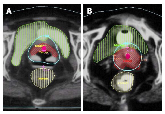
Figure 5 Tumour well covered within 6 Gy isodose volume (A) and tumour lying outside the 6 Gy isodose volume (B).
Reproduced with permission[28].
Figure 6 Positron emission tomography-computed tomography explore for brachytherapy planning in cervical cancers.
A and B: Positron emission tomography-computed tomography with the Vienna applicator; C and D: Depiction of the 6 Gy isodose volume. The tumour in relation to the applicator is visualized within the 6 Gy volume.
- Citation: Srivastava A, Datta NR. Brachytherapy in cancer cervix: Time to move ahead from point A? World J Clin Oncol 2014; 5(4): 764-774
- URL: https://www.wjgnet.com/2218-4333/full/v5/i4/764.htm
- DOI: https://dx.doi.org/10.5306/wjco.v5.i4.764


