INTRODUCTION
The role of the coronary venous system was not appreciated for many years. In the last 20 years, the number of percutaneous cardiology techniques in which the anatomy of the coronary venous system was significant were developed and are in use. The most important seems to be cardiac resynchronization therapy (CRT), which is an invasive method for the treatment of heart failure[1-5]. The most recent European guidelines for this method were published in 2012 and 2013[6,7]. In this method, an additional left ventricle (LV) lead is placed in the target coronary vein on the surface of the left ventricle. Proper implantation provides the possibility of pacing the left ventricle together with the classic pacing of the right ventricle and usually the right atrium The most important challenge of left ventricle lead implantation is the precise placement in the area where the electrical parameters are assumed to be optimal[8-10]. The lead is implanted via the right atrium by the cannulation of the coronary sinus (CS) ostium to the coronary sinus and the great cardiac vein to the lateral or posterolateral veins (typically), which are called the target veins[11,12]. Unfortunately, one of the major problems is the significant anatomical variability of the coronary venous system[13,14].
ANATOMY OF THE CORONARY VENOUS SYSTEM
The coronary sinus ostium is located in the posteroseptal area of the right atrium and is the final part of the coronary venous system. The coronary sinus usually begins in the place where the vein of Marshall (which is sometimes called the oblique vein of the left atrium) is typically connected to the great cardiac vein[9,15-18]. The vein of Marshall is a small vein that courses on the surface of the right atrium with the ligament of the left vena cava. Sometimes, the valve of Vieussens also occurs[19,20]. The role of the coronary sinus is to collect veins and join them together; it collects blood from the myocardium and delivers deoxygenated blood to the right atrium. The coronary sinus runs transversely in the right atrioventricular groove on the posterior side of the heart close to the distal part of circumflex branch of the left coronary artery[21-24]. The first branch, which is the beginning of the great cardiac vein is the anterior vein, is sometimes called the anterior interventricular vein and runs parallel to the left descending artery[25].
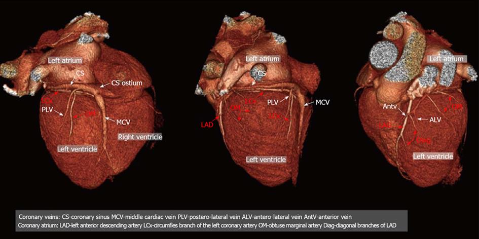
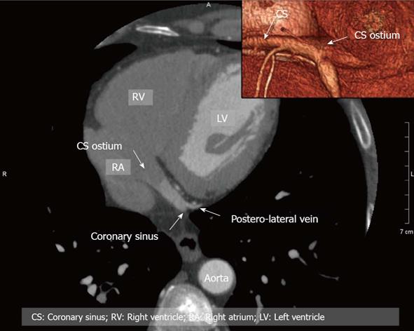
The area between the anterior vein and the middle cardiac vein is a place where more veins occur in different variants. Depending on the area of drainage, they are called the anterolateral, lateral, posterolateral and posterior veins. There are no strict borders on the left ventricle in the nomenclature of veins. Their number and locations depends on many factors (this will be the subject of a separate paragraph in this article due to its important function in many invasive cardiovascular procedures). Another border of the coronary venous system is the middle cardiac vein. The middle cardiac vein begins close to the apex of the heart and goes into the posterior interventricular groove and finally enters the coronary sinus close to the coronary sinus ostium[15,26,27]. A three-dimensional (3D)/2D reconstructions of the coronary venous system in cardiac computed tomography (CT) are presented in Figures 1 and 2.
Figure 1 Example of the three-dimensional (3D) anatomy of coronary vessels (arteries and veins).
Posterior, lateral antero-lateral view of the heart; 3D volume rendering projections. CS: Coronary sinus; MCV: Middle cardiac vein; PLV: Postero-lateral vein; ALV: Antero-lateral vein; AntV: Anterior vein; LAD: Left anterior descending artery; LCx: Circumfles branch of the left coronary artery; OM: Obtuse marginal artery; Diag: Diagonal branches of LAD.
Figure 2 Example of anatomy of coronary vessels in two-dimensional (2D)/3D with reference to the coronary sinus.
CS: Coronary sinus; RV: Right ventricle; RA: Right atrium; LV: Left ventricle.
COMPUTED TOMOGRAPHY
Since the beginning of cardiac CT, different authors have tried to examine the coronary venous system. At the very beginning, the papers usually had only anatomical merit. One of the first was Christiaens et al[25]. The authors examined 50 consecutive patients using 16-row MDCT (Siemens, Sensation 16). They were able to measure the coronary sinus in two directions, which were 12.2 ± 3.6 in the antero-posterior and 15.3 ± 3.7 in supero-inferior direction with a detailed analysis of the profile of the coronary sinus branches. The first paper that described the anatomical variants was the paper of Jongbloed et al[28]. They examined 38 patients using 16-slice CT (Toshiba, Aquilion 16) in which the insertion and continuity of the main tributaries, the number of antero and posterolateral tributaries and the distances between the main tributaries were evaluated. Another study using a 16-slice scanner was the study of Abbara et al[29]. The authors used a 16-slice scanner (Siemens, Sensation 16). The authors concluded the feasibility of CT coronary venous imaging especially in the planning of transvenous procedures where the cannulation of the coronary sinus is necessary. In this paper, the authors used an image-quality scale using both conspicuity and contrast-to-noise ratio (CNR), which is very precise; however, this was seldom used in papers that described the coronary venous system. The paper of Tada et al[30] discussed the examination of 70 patients using an 8-slice detector. The authors stressed that the venous flow shows an aphasic pattern during the cardiac cycle. This can be a crucial element for the image quality of the coronary venous system. In the paper of Tada, the CVS was greater on the reconstructions that were performed during systole. It can be seen that the images reconstructed in the diastolic phases can cause an underestimate CVS and its tributaries that is similar to the coronary arteries. Another paper describing the coronary venous system in cardiac CT using the latest generation scanner is a paper by Genc et al[31]. The authors prospectively examined 357 subjects who had undergone a cardiac CT due to coronary artery disease using a 128-slice Dual Source ECG-gated MDCT (Siemens). All of the veins were visualized in all of the included patients including at least one target vein for cardiac resynchronization. The posterior cardiac vein and the left marginal vein were visualized in approximately 87%, and the small cardiac vein in 20%. The results obtained by Genc et al[31] suggested more detailed images when compared to the older scanners (16-64 slices); however, for a pre-procedural clinical analysis/visualization any of the cardiac CT scanners should be acceptable; however, a more detailed post-processing and analysis of the images is recommended.
The above-mentioned papers influenced the evolution of the imaging the coronary veins and were a prelude to later papers.
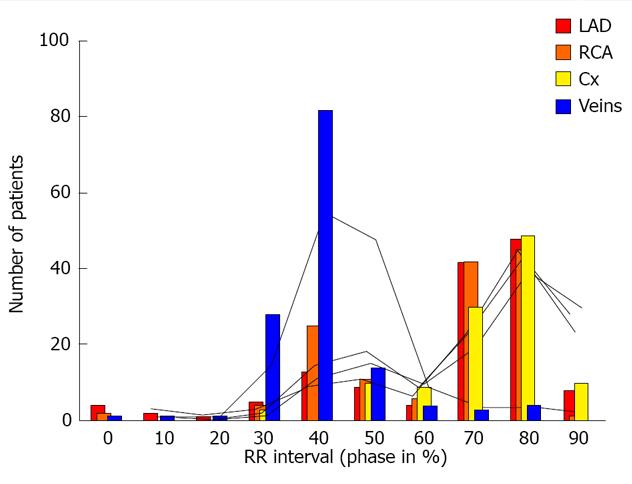
The challenge is how to visualize the coronary venous system in cardiac CT. In our earlier research, we documented that the optimal phases for reconstruction should be performed during diastolic phases 30%-50% RR. It can be easily performed on scanners with retrospective gating despite the higher dose of radiation[32]. In Figures 3 and 4 we present the influence of the phase of reconstruction on the visualization of heart vessels-veins and arteries.
Figure 3 Influence of the phase of reconstruction on the quality of reconstructions of the coronary arteries and veins.
Posterior and antero-lateral view of the heart; three-dimensional Volume rendering.
Figure 4 Influence of the phase of reconstruction on the quality of reconstructions of the coronary arteries and veins.
LAD: Left anterior descending artery; Cx: Circumfles
IMAGES AND CARDIAC RESYNCHRONISATION
A description of the selected anatomical structures is only useful in selected cases such as, for example, the obstruction of selected vessels, a huge Thebesian valve, etc. The images do have added value; however, their usefulness is limited due to the different points of view that are obtained during intra-operational fluoroscopy in comparison with 3D visualizations that are performed using cardiac CT. We attempted to resolve this problem in 2009. The results of our research were published in the PACE journal[33]. We determined that the key features that images must have are: (1) that they be similar in quality to intra-operative fluoroscopy; (2) that they give a semitransparent view of the heart; (3) that they show the semitransparent bones, sternum and vertebral column as a position reference for the implanting physician; (4) that they provide the anterior-posterior (AP), left anterior oblique (LAO) and right anterior oblique (RAO) views; and (5) that they show 3D views in order to evaluate all of the important anatomical aspects.
The cardiac veins are indicated using markers (3D arrows) that are added to the image during post-processing. Finally, the heart is corrected in order to fulfill AP, LAO and RAO-Figure 5[33]. By using this solution in 83 patients (74%), it was possible to obtain very similar images to those that were obtained during the CRT implantation procedure within all three views. In 24% patients, it was not possible to obtain the AP view with the coronary sinus and its ostium due to the large amount of contrast agent in the right heart. We were also able to visualize the coronary venous system with the vein of Marshall (23%) and the Thebesian valve in 41% of the patients. After seven years of experience with this method, in most cases we are able to obtain proper images. One prospective randomized trial in which Girsky et al[34] examined the usefulness of venous cardiac CT angiography for the facilitation of CRT implantation was also published. The authors included 26 patients who had full qualification for CRT-D implantation. The images of eight patients were analyzed using electron-beam CT and 18 patients using 64-slice CT. According to the methods described, the authors used prospective gating to reduce the radiation. They also used a two-second delay for imaging the coronary veins as a modification of routine coronary arteries visualization. According to their results, the CT images helped to decrease the time required for the cannulation of the coronary sinus and the total length of the procedures. A significant reduction in the utilization of a contrast agent, fluoroscopy and some of the equipment that was used was also observed.
Figure 5 Proposed scheme of reconstruction necessary to fulfill cardiac resynchronization therapy requirements[15].
RA: Right atrium; CS: Coronary sinus;.
There are a few technical-anatomical challenges during the implantation of a left ventricle lead. According to the Blendea and Singh[35], these can include: (1) Lack of successful coronary sinus cannulation caused by the Thebesian valve or a strange (narrow) angle of entrance from the right atrium; (2) Valve of Vieussens on the border of the coronary sinus and the great cardiac vein; (3) Accidental placement of the LV lead into the vein of Marshall, which is unacceptable for LV pacing; (4) Coronary sinus spasm or stenosis; and (5) Lack of target veins-posterolateral, lateral or sometimes anterolateral.
Images generated by cardiac CT can facilitate placement preparation of the procedure, shorten the time of implantation or lower the exposure to X-ray.
THEBESIAN VALVE
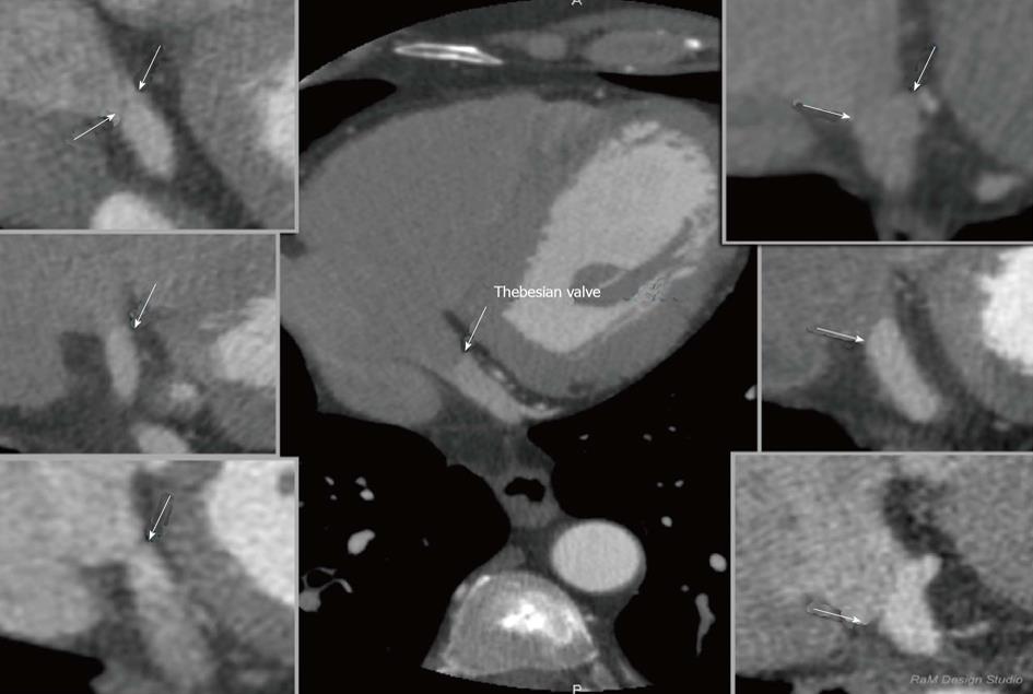
The Thebesian valve is the part of the cardiac anatomy that can present problems during coronary sinus cannulation. It is a semicircular fold membrane of the right atrium at the orifice of the coronary sinus, and it is a caudal remnant of the embryonic sinoatrial valve. It is situated at the base of the superior vena cava and sometimes is called the coronary sinus guard dog[36,37]. The valve may have a different size, shape or structure or it can be completely absent[38-43]. One of the largest researches that evaluated the Thebesian valve in autopsied hearts was presented in the paper by Mak et al[36]. A wide variety of Thebesian valve morphologies were observed in the 75 hearts that were examined, ranging from the absence of the valve to cases in which the valve completely occluded the CS ostium. A Thebesian valve was present in the majority of the hearts that were examined (55/75 hearts-73%). In a study of 50 human CSs of the heart, Silver and Rowley showed that the Thebesian valve covered the ostium in 41% of the cases, including 20% that were totally covered and in 26% of hearts that had an increased weight[44]. In contrast, El-Maasarany et al[45] obtained different results. In their study, the valve was present in 87.5% (35/40)-in those cases it was a thin semi-lunar fold. In four of the 40 patients (10%), the valve had the form of a narrow circular rim surrounding the ostium. The valve was absent in only one case. These differences between the researches indicate the huge anatomical variability of the coronary venous system. Based on our research we proposed a tomographic classification of the Thebesian valve[46]. Our paper was the first in which a heart failure subgroup (EF < 40%) was examined. This might be of special significance since this group is a potential target for cardiac resynchronization. In this group, the prevalence of the Thebesian valve appeared to be significantly lower as compared to groups with a preserved (41%-60%) or normal (approximately 60%) ejection fraction. However, there were no significant differences in the angle of entrance or in the CS diameter between the groups. The prevalence of the valve in heart failure patients is probably caused by atrial enlargement and the stretching of the CS as well as the Thebesian valve. In fact, the Thebesian valve can be relatively well described in MSCT. None of the authors have suggested that any special techniques are required for performing MSCT to visualize the Thebesian valve. A precise evaluation of a standard cardiac scan should be enough to describe this valve. An example of the visualization of Thebesian valve is presented in Figure 6.
Figure 6 Examples of thebesian valves in cardiac computed tomography; two-dimensional multi-planar reformatting projections.
INFLUENCE OF CARDIAC PATHOLOGIES ON THE CORONARY VENOUS SYSTEM
Most percutaneous cardiological procedures are performed in patients with different pathologies of the heart. The question of whether those pathologies significantly influence the coronary venous system is interesting. Computed tomography of the heart is an ideal tool to perform such research. In 2007 Chen et al[47] examined 23 consecutive patients with chronic systolic heart failure and an ejection fraction < 40%. The authors concluded that heart failure extends the total length between the PIV and AIV as compared to the control group. Similar results were also obtained by our team[48]. During MSCT of patients with heart failure, the average number of visible veins per case was 3.44 in the HF group and 2.72 in patients with a normal ejection fraction (P = 0.0246). The statistical correlation between a reduction in ejection fraction and an increase in the number of veins was found (r = -0.2446, P < 0.05). We also examined the influence of heart failure on the variants of the coronary venous system and found that for two of the seven common variants of the coronary venous system at least two target veins (posterolateral and lateral) were presented for cardiac resynchronization. We concluded that an association possibly exists between a failing heart and cardiac venous retention.
Another important question is whether there are some problems with performing MSCT in heart failure patients. First of all, we have to look at the volume of contrast agent because renal impairment often coexists in HF patients, secondly because the use of beta blockers to stabilize the heart rhythm are often contraindicated in these patients and finally these patients often have a problem holding their breath, which is necessary in order to avoid any motion artifacts[49]. Another important observation is the coronary venous system in patients after bypass grafts[50]. We documented that the average number of visible coronary veins in the CABG group was significantly higher (5.3 ± 1.3), while in the control group, it was 3.1 ± 1.1 (P = 0.001). An example of such an image is presented in Figure 7.
Figure 7 Example of coronary venous system in patients after CABG; three-dimensional Volume rendering.
PERCUTANEOUS MITRAL ANNULOPLASTY
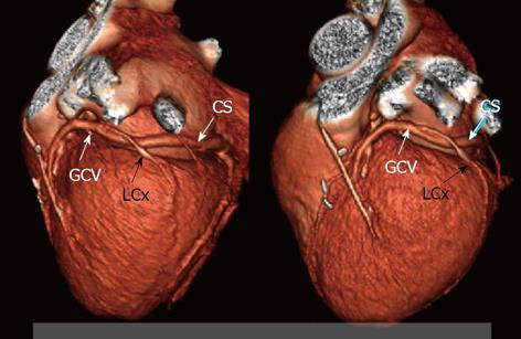
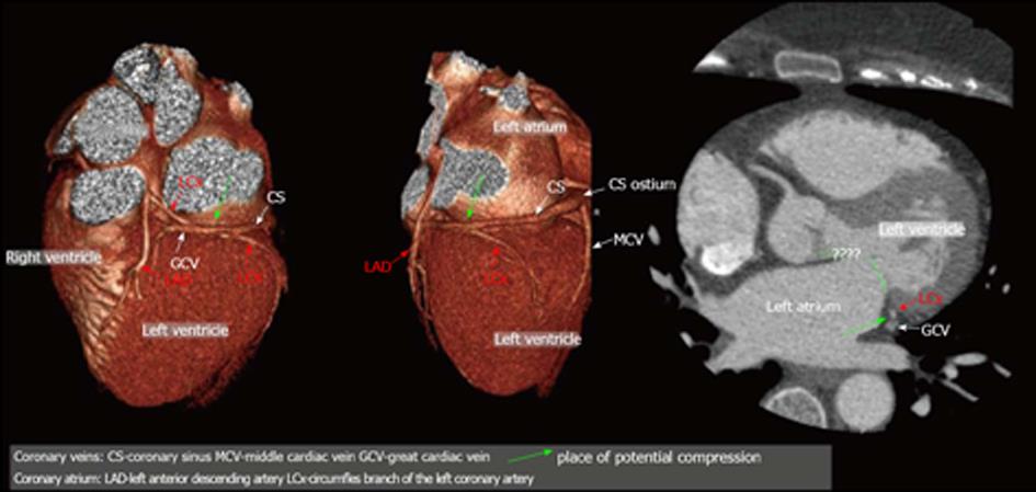
Percutaneous mitral annuloplasty (PMA) is another method in which the visualization of the coronary venous system is important. In this technique devices are implanted into the coronary sinus and the great cardiac vein in order to reduce mitral ischemic regurgitation[51-55]. Its safety and usefulness were evaluated in human studies such as the AMADEUS trial[56,57]. Why is knowledge about the anatomy so important? In selected patients, a close relationship between the left circumflex artery (LCx) and the coronary sinus can cause the LCx to be accidently occluded during the placement of a device-an example is presented in Figure 8. Computed tomography allows the visualization of the relationships between the mitral valve (MV), the LCx and CS and therefore the risk of occluding the LCx can be minimized[58-60]. Mutual relations between coronary sinus / great cardiac vein and the circumflex branch of left coronary artery-potential role before percutaneous mitral annuloplasty are presented in Figure 9. Several studies have confirmed the considerable anatomical variability in the relative positions of the LCx, the CS and the MV. For example, Maselli et al[61] examined the hearts of 61 patients who had died of non-cardiological causes. In the era of non-invasive procedures, visualization using MSCT can play a vital role. One of the earliest studies was that of Maselli et al[61] in 2007. The authors analyzed 105 consecutive patients who had been referred for MSCT coronary angiography. Patients were divided into three groups depending on the presence of CAD and heart failure. They concluded that the LCx, CS and mitral valve could be analyzed. Another study evaluating the relationship of the coronary sinus and great cardiac vein to the mitral annulus is a paper by del Valle-Fernandez et al[62]. The authors reviewed 390 CT angiograms in order to evaluate patients with a coronary sinus that was more than 200 Hounsfield units in phases 40%, 75% and 0% RR, the absence of a mitral prosthesis and without any anomalies or diseases of the mitral valve. A 64-slice scanner was used in this research and 56 patients were chosen for the final analysis. The authors were able to precisely evaluate the anatomical relationship between the mitral annulus and the coronary sinus. They concluded that the distance between the CS and the mitral annulus varies along the cardiac cycle. The authors also found that the LCx lies between the CS and the mitral annulus in 86% of the subjects that were included.
Figure 8 Mutual relations between coronary sinus/great cardiac vein and circumflex branch of left coronary artery-twisted variant which is very risky for LCx compression by PMA device; three-dimensional Volume rendering.
CS: Coronary sinus; GCV: Great cardiac vein; LCx: Circumflex branch.
Figure 9 Mutual relations between coronary sinus/great cardiac vein and circumflex branch of left coronary artery - potential role before percutaneous mitral annuloplasty; three-dimensional Volume rendering.
CS: Coronary sinus; MCV: Middle cardiac vein; PLV: Postero-lateral vein; ALV: Antero-lateral vein; AntV: Anterior vein; LAD: Left anterior descending artery; LCx: Circumfles branch of the left coronary artery.
PLACE ON INTERNATIONAL GUIDELINES
Most papers have had a huge influence on the creation of clinical guidelines-in the 2010 version of the appropriate use criteria for cardiac CT, noninvasive coronary vein mapping prior to the placement of a biventricular pacemaker received an A (8), which means that it is highly recommended[63]. When the imaging technology was evaluated and the images started to have an acceptable quality and became more common, creating clinical-practical guidelines was only a matter of time. The most important seem to be the 2012 EHRA/HRS expert consensus statement on cardiac resynchronization therapy in heart failure: implant and follow-up recommendations and management[64]. In this document some key elements of using CT before cardiac resynchronization were outlined including the statement that cardiac CT angiography provides a detailed assessment of the coronary arteries and can image and quantify the coronary venous system, including branch vein variability and potential obstacles to placement prior to a CRT procedure in individual patients. There are also limited data suggesting that pre-procedural knowledge about the 3D coronary venous anatomy can facilitate CRT by decreasing the length of the procedure, the time that the patient is receiving radiation and the utilization of guide catheters. The authors also stressed that the target population for cardiac resynchronization-the heart failure population-is not the overall population and can cause some difficulties such as the necessity of using a contrast agent during CT, the ability to do a breath-hold, proper renal function and sometimes the necessity of using intravenous B-Blockers to control the rhythm, which can be contraindicated in the heart failure population.
LIMITATIONS OF COMPUTED TOMOGRAPHY BEFORE ELECTROPHYSIOLOGY PROCEDURES
As was written previously, and underlined in the guidelines, CT is not an examination for the entire population. There are some limitations that apply mostly to patients with heart failure who are potentially qualified for CRT such as: (1) Necessity of a breath hold-elderly patient with advanced heart failure can have problems with this and this can cause motion artifacts; (2) Heart rhythm below 65/min-a higher value than 65/min sometimes requires the administration of Beta Blockers, which can be contraindicated in this population; and (3) During procedures like CRT a large amount of contrast agent, which is also used during CT, is used. This can cause significant problems in the population who suffer from renal failure-prophylaxis of contrast-induced nephropathy should be implemented.
Some physicians are also afraid of the dosage of radiation, which is substantial during CT. Fortunately, progress in the manufacture of CT scanners means that this dosage is continuously decreased by the new techniques that are used in the latest scanners. An example of this is the visualization of the pulmonary veins with a low dosage by using a dual source CT[65]. To date there are no data to support a direct link between CT imaging and a future risk of developing cancer; however, health care practitioners should make every effort to minimize their patients’ radiation exposure[66].
CONCLUSION
After summarizing all of the articles and guidelines, it can be recommended that the visualization of the coronary venous system be considered in certain patients before cardiac resynchronization. The best option is to use tomography with a retrospective ECG gating. Typically, the optimal reconstruction of cardiac veins is during the diastolic phases (30%-40% and 50%) and in our opinion this might complement the standard reconstruction for coronary arteries. If a candidate for CRT had an MSCT examination with retrospective gating performed earlier, it is possible to refer to this exam and reconstruct the coronary venous system without exposing the patient to additional radiation. However, it is necessary to remember that because some diseases or the progress of some diseases can significantly influence the coronary venous tree anatomy, the period between the MSCT exam and CRT should not be too long. In most cardiac resynchronization centers, CRT is almost a routine procedure-it is difficult to recommend MSCT visualization as a routine procedure because intra-operational fluoroscopy is usually enough for the proper implantation of a left ventricle lead. However, in certain cases where difficulties in cannulation are expected, a pre-procedural MSCT should be considered.
Considering and recommending MSCT before percutaneous mitral annuloplasty is too early because of the lack of experience with this method, even in cases in which some device had received a CE mark. However, in such a situation, parallel reconstruction during the systolic (70%-80%) and diastolic phases (30%-40%-50%) should be considered in order to define the anatomical relation between the mitral valve, the coronary sinus and the circumflex branch of the left coronary artery with the highest precision.
P- Reviewer: Gong QY, Mani V, Storto G, Vogl TJ S- Editor: Wen LL L- Editor: A E- Editor: Lu YJ


