Published online Nov 28, 2010. doi: 10.4329/wjr.v2.i11.440
Revised: July 30, 2010
Accepted: August 6, 2010
Published online: November 28, 2010
AIM: To present our experience of using 3D virtual intravascular endoscopy (VIE) to characterize and evaluate the intraluminal appearances of aortic dissection.
METHODS: Ten patients with known aortic dissection underwent dual-source computed tomography angiography and were included in the study. In addition to 2D axial and multiplanar reformatted images as well as 3D reconstructions, VIE images were created in each patient to demonstrate intraluminal views of the aorta and its branches, origin of artery branches and artery branch involvement by aortic dissection.
RESULTS: Stanford A dissection was found in 8 patients and B dissection in the remaining 2 patients. VIE images were successfully generated in all of the patients with excellent visualization of the normal anatomical structures, intimal flap and intimal entrance tear, communication between true and false lumens, as well as assessment of the extent of aortic dissection.
CONCLUSION: Our preliminary experience suggests that VIE could be used as a complementary tool to assist radiologists accurately evaluate aortic dissection so that better patient management can be achieved.
- Citation: Sun Z, Cao Y. Multislice CT virtual intravascular endoscopy of aortic dissection: A pictorial essay. World J Radiol 2010; 2(11): 440-448
- URL: https://www.wjgnet.com/1949-8470/full/v2/i11/440.htm
- DOI: https://dx.doi.org/10.4329/wjr.v2.i11.440
Aortic dissection is a common vascular disease and it is the most frequent cause of aortic emergency. Aortic dissection can be a life-threatening event which is characterized by splitting of the aortic wall by high blood pressure entering the media through an intimomedial entrance tear. Multislice computed tomography (CT) angiography is the preferred method for diagnosis of aortic dissection with a sensitivity and specificity of nearly 100%[1,2]. CT has been shown to be more sensitive than invasive angiography and is comparable to MR imaging and transesophageal echocardiography for diagnosis of aortic dissection[3,4].
Aortic dissection leads to formation of true and false lumens which are separated from each other by a flap of intimal lining and inner layers of media. Outer layers of the aortic media and adventitia form the outer wall of the false lumen which is most commonly larger than the true lumen due to lack of outlet of blood flow. Differentiation between true and false lumens is important in the planning of percutaneous treatment with endovascular stent grafts or surgical repair of aortic dissections[5,6]. It is crucial to identify the lumen of origin in major branch vessels such as coronary, carotid, renal and mesenteric arteries before treatment because viscera supplied by the false lumen are at risk when the false lumen is spontaneously or surgically occluded[7]. The criteria to distinguish true from false lumens by CT have been previously described[5,8]. In most of the cases, axial CT imaging supplemented by 2D or 3D reconstructions is able to identify the intimal flap which separates the true lumen from the false lumen and determine the type and extent of dissection; however, this may not be possible in all cases due to variable appearances resulting from different types of aortic dissection[9,10].
3D virtual intravascular endoscopy (VIE) provides unique intraluminal views of the blood vessel and it has been previously reported to be valuable for assessment of aortic aneurysms and endovascular stent grafts[11-13]. VIE has been shown to offer better understanding of the abnormalities of the aortic arch after endovascular repair[14]; however, investigation of variable imaging appearances of aortic dissection by VIE visualization has not been studied before, to the best of our knowledge. The purpose of this paper is to demonstrate VIE findings in a group of patients diagnosed with aortic dissection. We present our experience of using VIE visualization in the assessment of aortic dissection with the aim of exploring the potential value of VIE for identification of the common and uncommon findings related to the aortic dissection with special focus on the identification of entry site or intimal tears of aortic dissection.
Ten patients (7 men and 3 women, age range: 39-77 years, mean age: 55 years) with known aortic dissection were retrospectively included in this study. All patients underwent spiral CT angiography (CTA) which was performed with a dual-source CT scanner (Siemens, Definition, Forchheim, Germany). The scanning protocol was as follows: beam collimation 64 mm × 0.6 mm with slice thickness between 0.5-1.0 mm, pitch 1.0 with reconstruction interval of 50% overlap. Non-ionic contrast medium (Visipaque) with a total volume of 100 mL was injected intravenously via the antecubital vein at a flow rate of 4-6 mL/s, followed by 40-60 mL normal saline chasing. A bolus triggering technique was used with the region of interest placed at the proximal descending thoracic aorta and the triggering threshold was set at 120 HU to initiate the scan.
Aortic dissection was characterized based on 2D images as Stanford type A in 8 patients and type B dissection in the remaining 2 patients. In addition to 2D axial views, multiplanar reformation and 3D volume rendering including VIE images were generated in each patient.
Since patients’ details were removed from the DICOM data, and all of the images were anonymous during post-processing, there was no ethical issue involved so no IRB approval was required for the study.
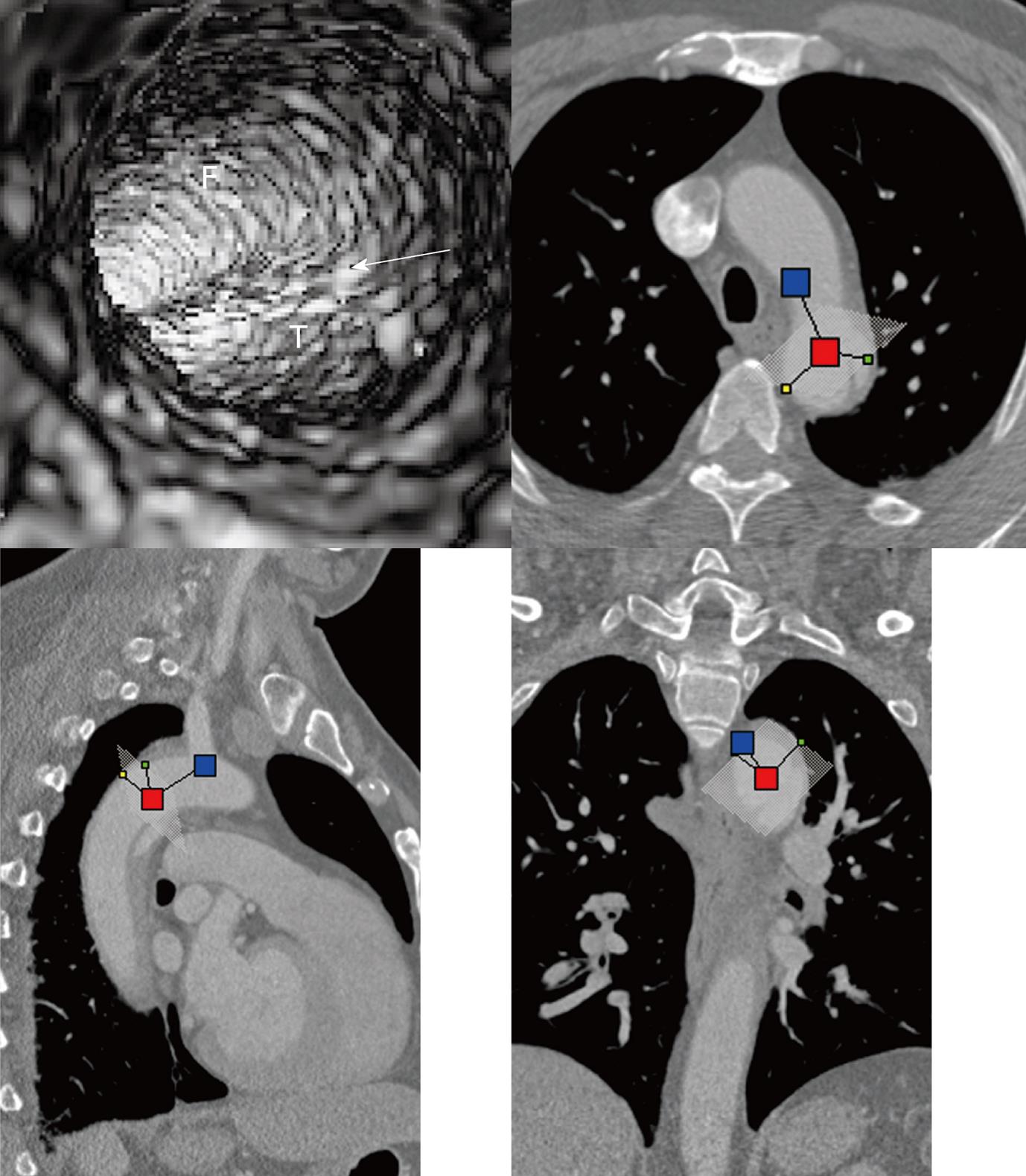
Multislice CT volume data were converted from original DICOM (Digital Imaging and Communication in Medicine) images using Analyze 7.0 (http://www.analyzedirect.com). VIE images were generated based on a CT number thresholding technique to provide intraluminal views of the aorta and its branches as well as abnormal changes[11,12]. VIE demonstration of both normal anatomical structures and pathological changes were determined by selecting an appropriate threshold value through measuring the CT attenuation at the aorta (either ascending or descending aorta or abdominal aorta). An upper threshold of 200-300 HU was applied to remove the contrast-enhanced blood from the aorta while keeping the artery wall intact without luminal disruption. Orthogonal views were referenced to assist VIE identification of the true and false lumens as well as intimal flap and entry site of aortic dissection (Figure 1).
Initially, it took about 30 min to produce VIE images for each patient. This includes a series of steps such as the conversion of DICOM images into volume data, image segmentation and generation of various VIE views of the aortic dissection. With experience gathered, the time was shortened to about 10-15 min for each case.
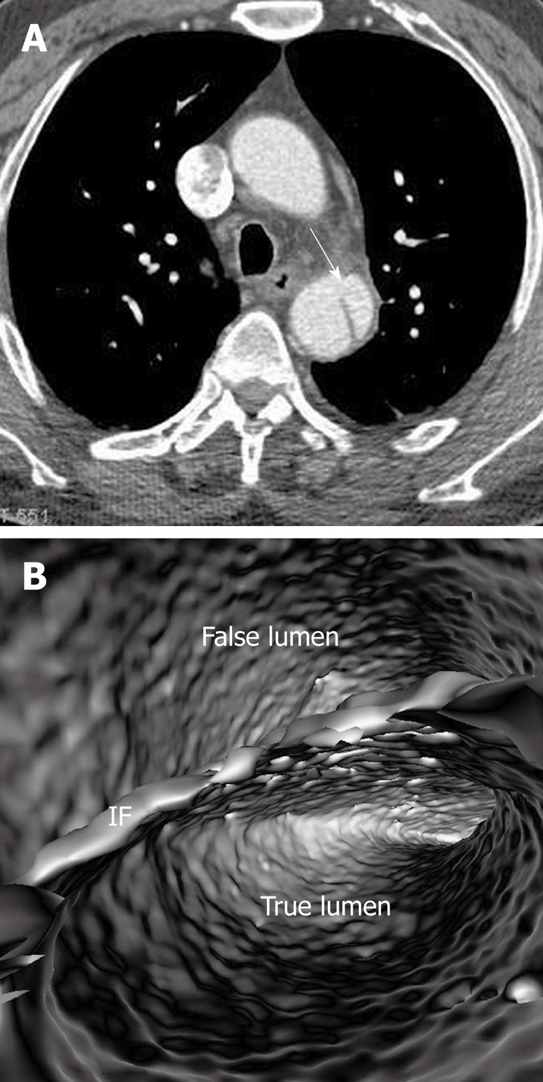
In most cases, the false lumen is larger than the true lumen as once the blood enters the false lumen via an intimal tear it accumulates inside the lumen without any outlet. The false lumen then gradually becomes larger and compresses the true lumen which is in contact with the non-dissected portion of the aorta (Figure 2). A thrombus is frequently formed in the false lumen (Figure 2A), and this results in low CT attenuation when compared to the true lumen. Therefore, for VIE visualization of true and false lumens, different CT thresholds need to be selected for demonstration of individual lumens clearly (Figure 2B).
The intimal flap is a soft tissue structure that separates the true lumen from the false lumen. The intimal flap can be seen in about 70% of cases in classic dissections[1]. If the CT attenuation measured in the true lumen is similar to that measured in the false lumen, VIE is able to demonstrate both lumens separated by the intimal flap in a single image (Figure 3). However, in the majority of cases, contrast enhancement in the true lumen is higher than that in the false lumen, thus VIE visualization of these two lumens is normally presented in separate images as different thresholds are required to demonstrate individual lumens. This indicates that the intimal flap is not usually displayed on a single VIE image since different intraluminal views are generated by showing the individual lumens separately (either true lumen or false lumen) (Figure 2B and C).
If the false lumen is thrombosed, the intimal flap may be difficult to recognise on CT images; thus it is difficult to distinguish and differentiate acute dissection from mural thrombus or intramural hematoma (Figure 4A). The limitation of conventional visualizations can be overcome with intraluminal endoscopic views, even if in the presence of significantly stenosed lumens (Figure 4B and C).
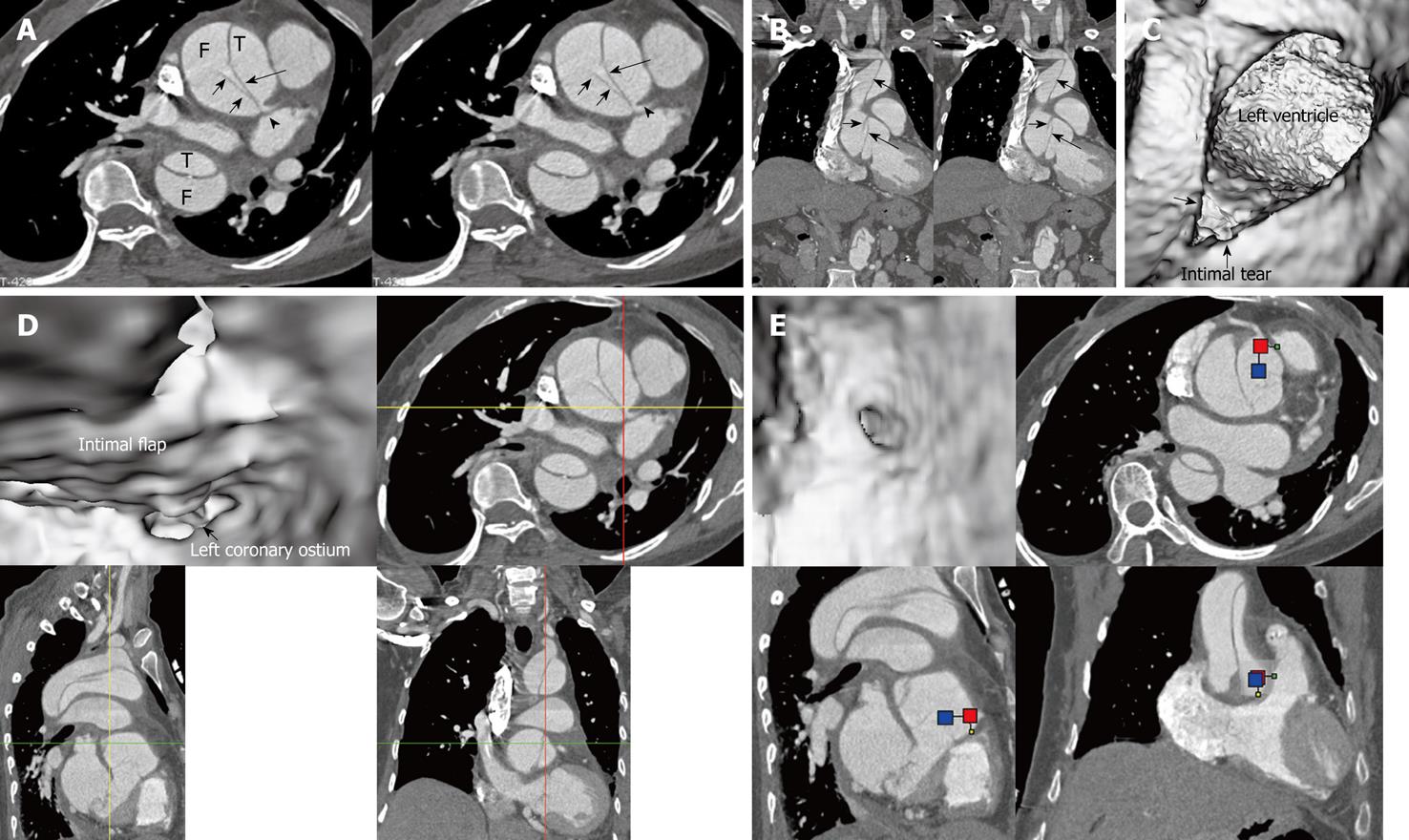
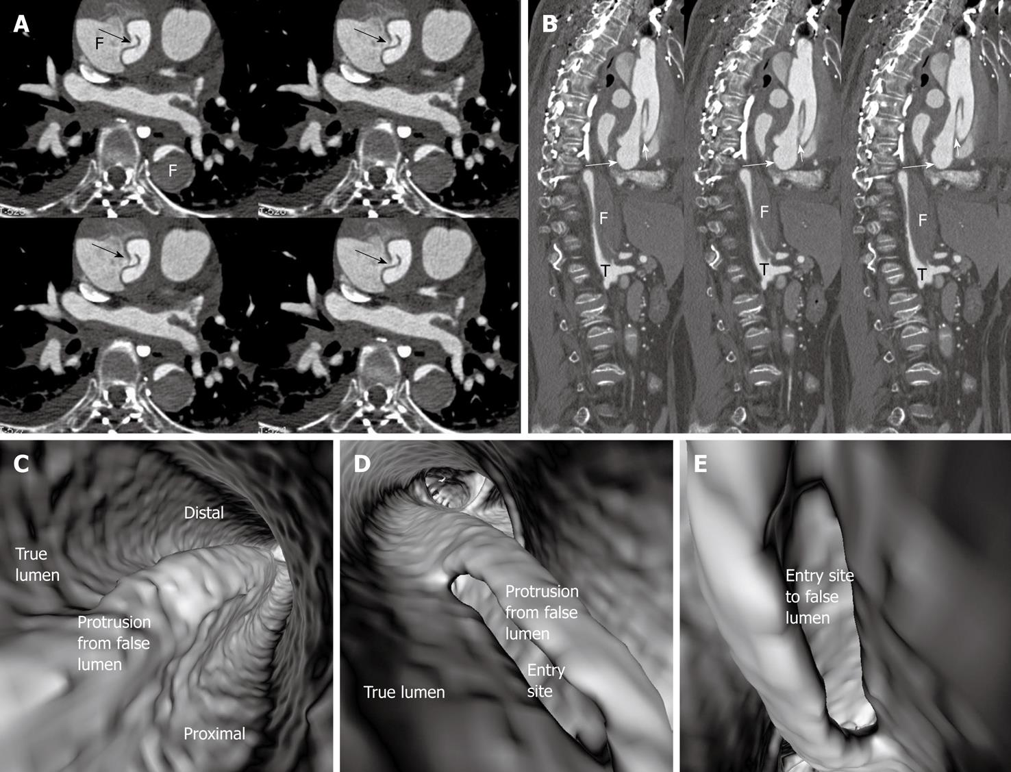
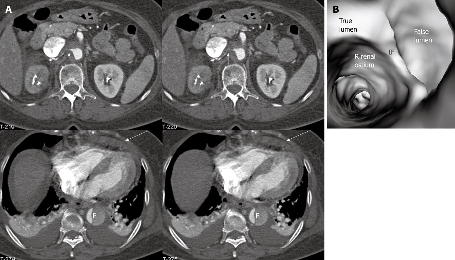
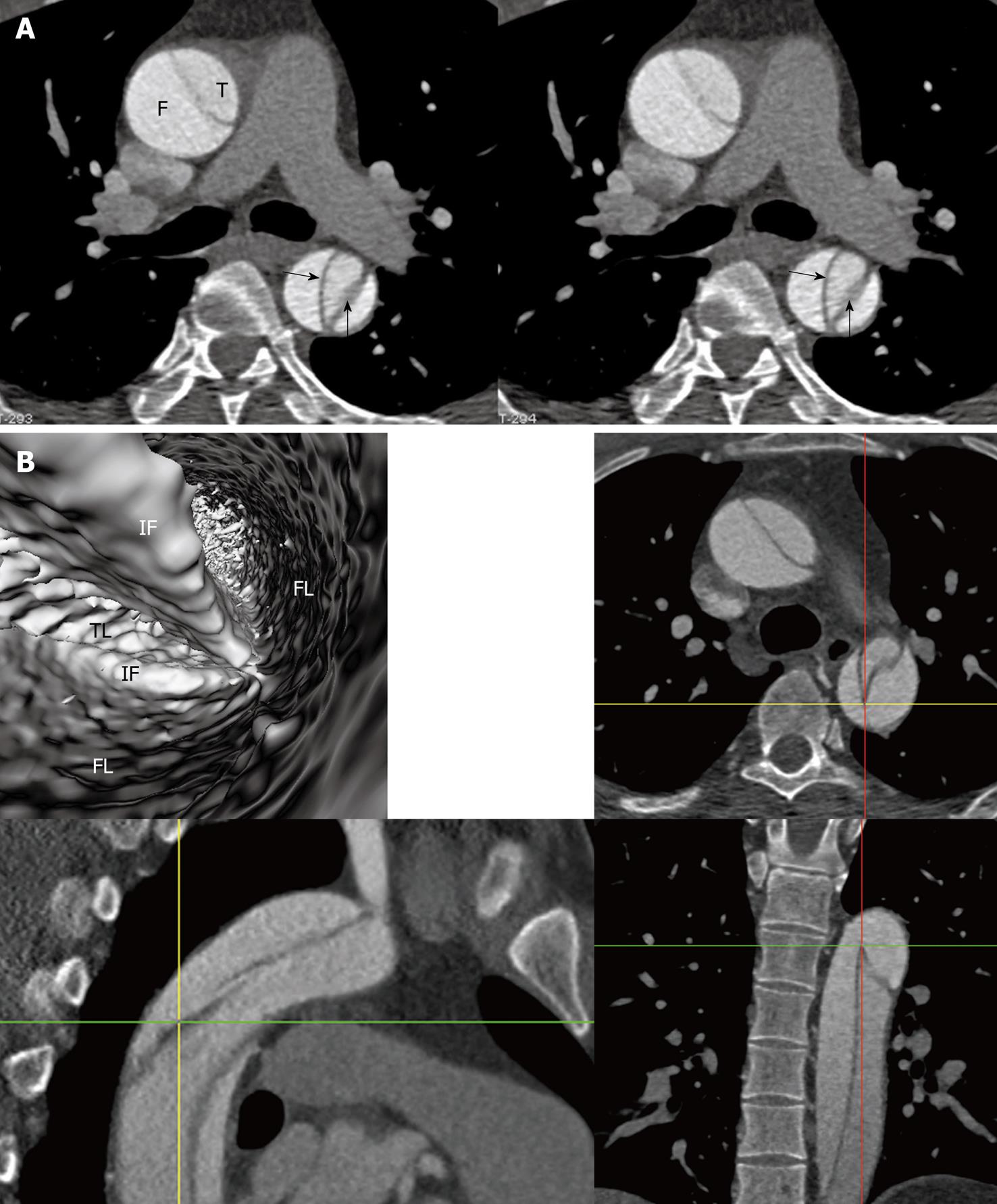
Identification of the accurate location of an intimomedial entrance tear is clinically important for diagnostic and therapeutic purposes. VIE is advantageous in this aspect as it enables generation of intraluminal views and clearly shows the communication between true and false lumens (Figure 5). In some complicated cases, VIE is able to confirm the entry site by navigating through the aorta and its branches including coronary branches (Figures 5 and 6). Moreover, VIE is able to determine the extent of the intimal tear which is believed useful for pre-operative evaluation of aortic dissection (Figures 5D and 6C).
Identification of vessel involvement by aortic dissection can be confirmed by 2D axial images in most situations (Figure 7A). VIE could be used as a complementary tool to 2D images in indeterminate cases, as virtual fly-through allows the viewers to follow the direction of dissection and identify whether the individual aortic branches are involved in the dissection (Figures 2B, 5D, 7B and 8). VIE assessment of vessel involvement is still possible even if in the presence of a severely narrowed true lumen due to compression by the false lumen (Figure 9).
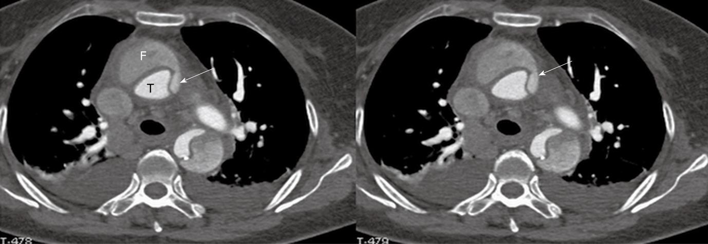
In addition to the above-mentioned imaging findings related to the aortic dissection, there are other typical and atypical features which are also observed in aortic dissection. The slender linear areas of low attenuation that occasionally appear in the false lumen on CT images, known as the cobweb sign, are specific to the false lumen and may aid in its recognition (Figures 5 and 10). Another usual indication of the false lumen is the beak sign, which is an imaging manifestation of the wedge of hematoma that cleaves a space for the propagation of the false lumen (Figure 11). The beak sign is a characteristic feature of the false lumen. These two findings can be easily identified and confirmed on 2D axial images, while VIE visualization does not present with characteristic features.
Intimointimal intussusception is an unusual manifestation of aortic dissection caused by circumferential dissection of the intimal layer[1]. In intimointimal intussusception, CT scans may show one lumen wrapped around the other lumen in the aortic arch or descending aorta, with the inner lumen always being the true lumen (Figure 12A). VIE clearly shows the central true lumen surrounded by the peripheral false lumen via two intimal flaps (Figure 12B), and the intraluminal visualization is enhanced by virtual fly-through viewing.
The principal complications of aortic dissection are cardiac rupture, cardiac failure and end-organ ischemia. The aorta gives rise to many important branches that include coronary arteries, carotid and vertebral arteries, subclavian arteries, lumbar arteries, celiac and mesenteric arteries, renal arteries and iliac arteries. These branch arteries can become poorly perfused due to obstructions at their origin, as would happen if the artery branch was thrombosed during dissection[15]. It is imperative to determine whether these major branch arteries originate from true or false lumens before interventional procedures such as placement of endovascular stent grafts or stents[5,6,8], because any branch vessels supplied by the false lumen may be occluded with an intervention unless surgically bypassed. Medical imaging techniques play an important role in this aspect.
High resolution CT imaging is the method of choice for diagnosis of aortic dissection and identification of true and false lumens, as well as determination of the aortic branches in relation to the dissection[2,10]. The most reliable direct imaging sign observed by CT for differentiating the true from false lumens is the ability to demonstrate direct continuity between the true lumen and the lumen of the uninvolved aortic lumen distal or proximal to the dissected aortic segment. This may not always be possible because the dissection may extend proximally into the aortic root, or the origin of the intimomedial entrance tear is at the convexity of the aortic arch where the true and false lumens may be difficult to follow[7,9]. The limitation of 2D CT imaging is complemented by multiplanar reformation and 3D reconstructions. Our experience of using VIE for assessment of aortic dissection, especially in the identification of intimal tears shows the feasibility of VIE visualization in complex cases of dissection.
In addition to the identification of the entry site, determination of the extent of the entry site can be further explored by VIE and assessment of vessel involvement can be confirmed even if for visualization of the tiny artery branches such as coronary arteries, as shown in Figures 5 and 6. We believe VIE could be used as a complementary tool to conventional CT visualizations for accurate assessment of the aortic dissection.
VIE image quality is determined by an appropriate threshold selection. Demonstration of true and false lumens is dependent on CT attenuation measured in each compartment. The intimal flap has a soft tissue density and presents as a linear structure; thus, it is commonly shown as an irregular linear structure which separates the true lumen from the false lumen (Figure 10B). Detecting full-directional information about the dissection should be assisted with cross-sectional and multiplanar reformatted CT images. Correlation with orthogonal views is necessary to confirm the exact position of anatomic details on VIE visualization, especially to assess the aortic branches with regard to their relationship to the dissection.
With the current multislice CT scanners such as the 64-slice or dual source CT, acquisition of isotropic volume data is possible so that high resolution original data is generated to ensure the image quality of VIE images[16,17]. In our small group of patients whose CT scans were performed with a dual source CT scanner, VIE was successfully generated in all of the patients with clear demonstration of anatomical details including the linear structure of intimal flap. Rapidly technical developments have significantly enhanced the diagnostic value of CT in the detection and evaluation of aortic dissection.
In conclusion, in this pictorial essay, we demonstrated the applications of VIE for visualization of aortic dissection and identification of true and false lumens, intimal flap and intimal entry site. Our preliminary study shows that VIE is a feasible 3D visualization tool which could be used to assist radiologists to accurately evaluate aortic dissection so that better patient management could be achieved.
Aortic dissection is a common vascular disease which carries high mortality if not diagnosed and treated appropriately. Despite high diagnostic value of computed tomography (CT) angiography in the diagnosis of aortic dissection, its accuracy to identify the location of an intimal tear or entry site is limited in some complicated cases. This study presents the advantages of 3D virtual intravascular endoscopy (VIE) for identification of intimal tear and assessment of vessel involvement in aortic dissection.
Extended application of 3D VIE to the patients with aortic dissection, thus, improving understanding of the dissection extent and vessel involvement for surgical planning.
Aortic dissection is routinely diagnosed and evaluated with CT angiography through a combination of 2D and 3D visualizations. This study presents advanced applications of VIE in aortic dissection by demonstrating findings which cannot be achieved with traditional image visualizations.
Our preliminary study shows the potential value of VIE in aortic dissection. Further studies based on a large cohort are needed to compare the diagnostic value of VIE with traditional 2D/3D visualizations.
VIE is a method of image data visualization using computer processing of 3D image datasets (such as CT or MR scans). It can provide visualizations of vascular structures similar or equivalent to those produced by standard endoscopic procedures.
It's a well written pictorial essay about 3D VIE in aortic dissection. There are many figures showing aortic dissection and their 3D VIE views.
Peer reviewers: Ender Uysal, MD, Sisli Etfal Training and Research Hospital, Clinic of Radiology, Sisli Etfal Eğitim ve Araştırma Hastanesi Radyoloji Kliniği, Etfal sok. Sisli, Istanbul 34377, Turkey; Peter Gaines, Professor, Sheffield Vascular Institute, Northern General Hospital, Sheffield, S5 7AU, United Kingdom
S- Editor Cheng JX L- Editor O’Neill M E- Editor Zheng XM
| 1. | Castañer E, Andreu M, Gallardo X, Mata JM, Cabezuelo MA, Pallardó Y. CT in nontraumatic acute thoracic aortic disease: typical and atypical features and complications. Radiographics. 2003;23 Spec No:S93-S110. |
| 2. | Sebastià C, Pallisa E, Quiroga S, Alvarez-Castells A, Dominguez R, Evangelista A. Aortic dissection: diagnosis and follow-up with helical CT. Radiographics. 1999;19:45-60; quiz 149-150. |
| 3. | Cigarroa JE, Isselbacher EM, DeSanctis RW, Eagle KA. Diagnostic imaging in the evaluation of suspected aortic dissection. Old standards and new directions. N Engl J Med. 1993;328:35-43. |
| 4. | Small JH, Dixon AK, Coulden RA, Flower CD, Housden BA. Fast CT for aortic dissection. Br J Radiol. 1996;69:900-905. |
| 5. | LePage MA, Quint LE, Sonnad SS, Deeb GM, Williams DM. Aortic dissection: CT features that distinguish true lumen from false lumen. AJR Am J Roentgenol. 2001;177:207-211. |
| 6. | Williams DM, Lee DY, Hamilton BH, Marx MV, Narasimham DL, Kazanjian SN, Prince MR, Andrews JC, Cho KJ, Deeb GM. The dissected aorta: percutaneous treatment of ischemic complications--principles and results. J Vasc Interv Radiol. 1997;8:605-625. |
| 7. | Kapoor V, Ferris JV, Fuhrman CR. Intimomedial rupture: a new CT finding to distinguish true from false lumen in aortic dissection. AJR Am J Roentgenol. 2004;183:109-112. |
| 8. | Williams DM, Joshi A, Dake MD, Deeb GM, Miller DC, Abrams GD. Aortic cobwebs: an anatomic marker identifying the false lumen in aortic dissection--imaging and pathologic correlation. Radiology. 1994;190:167-174. |
| 9. | Scaglione M, Salvolini L, Casciani E, Giovagnoni A, Mazzei MA, Volterrani L. The many faces of aortic dissections: Beware of unusual presentations. Eur J Radiol. 2008;65:359-364. |
| 10. | Berger FH, van Lienden KP, Smithuis R, Nicolaou S, van Delden OM. Acute aortic syndrome and blunt traumatic aortic injury: pictorial review of MDCT imaging. Eur J Radiol. 2010;74:24-39. |
| 11. | Sun Z, Winder RJ, Kelly BE, Ellis PK, Hirst DG. CT virtual intravascular endoscopy of abdominal aortic aneurysms treated with suprarenal endovascular stent grafting. Abdom Imaging. 2003;28:580-587. |
| 12. | Sun Z, Winder RJ, Kelly BE, Ellis PK, Kennedy PT, Hirst DG. Diagnostic value of CT virtual intravascular endoscopy in aortic stent-grafting. J Endovasc Ther. 2004;11:13-25. |
| 13. | Sun Z, Allen YB, Nadkarni S, Knight R, Hartley DE, Lawrence-Brown MM. CT virtual intravascular endoscopy in the visualization of fenestrated stent-grafts. J Endovasc Ther. 2008;15:42-51. |
| 14. | Louis N, Desgranges P, Kobeiter H, Kirsch M, Becquemin JP. Virtual angioscopy and 3-dimensional navigation findings of the aortic arch after vascular surgery. Circulation. 2009;119:1052-1055. |
| 16. | Brodoefel H, Burgstahler C, Tsiflikas I, Reimann A, Schroeder S, Claussen CD, Heuschmid M, Kopp AF. Dual-source CT: effect of heart rate, heart rate variability, and calcification on image quality and diagnostic accuracy. Radiology. 2008;247:346-355. |
| 17. | Leschka S, Alkadhi H, Plass A, Desbiolles L, Grünenfelder J, Marincek B, Wildermuth S. Accuracy of MSCT coronary angiography with 64-slice technology: first experience. Eur Heart J. 2005;26:1482-1487. |


