ENDOVASCULAR REPAIR (EVAR) OF ABDOMINAL AORTIC ANEURYSM (AAA)-TECHNICAL DEVELOPMENTS
EVAR of AAA has been confirmed as an effective alternative to open surgery due to its lower invasiveness and reduced morbidity and mortality, and lower overall treatment cost[1,2]. Since its first introduction into the clinical practice in 1991, endovascular stent grafting has been widely used in clinical practice with satisfactory results being achieved[1-5]. Over the last decade, the technique of endovascular stent grafting has progressed rapidly following an improved understanding of the strengths and limitations of various devices and treated patient populations[3-6]. Application of this technology is still limited to patients with suitable proximal and distal sealing zones. It is estimated that up to 40% of patients are unsuitable for conventional infrarenal EVAR as complicated aneurysm necks prevent the patients from being candidates to receive treatment with placement of stent grafts infrarenally due to inadequate sealing zones in the aneurysm neck[5,6].
Unfavorable aneurysm necks (neck length less than 10 mm, severe angulation > 60°, and severe calcification or presence of thrombus in the aneurysm neck) remain challenging for conventional infrarenal EVAR, and this has been addressed by using suprarenal and fenestration endovascular techniques[5-10]. Currently, helical computed tomography (CT) angiography is the preferred method for assessment of suprarenal and fenestrated stent grafting due to its rapid technical developments, which allow for acquisition of high spatial and temporal resolution images[11-13].
In addition to CT imaging, ultrasound and magnetic resonance imaging (MRI) are other two imaging modalities that play an increasing role in follow-up of EVAR of AAA. Ultrasound is less expensive and does not involve ionizing radiation or potentially nephrotoxic contrast[14,15]. Several studies reported the usefulness of contrast-enhanced ultrasound, because it seems to allow better identification and characterization of endoleaks[16-18]. Particularly, contrast-enhanced ultrasound was found to detect a low-flow endoleak classified as endotension on the basis of triple contrast-enhanced CT[16].
MRI is less commonly used than CT and ultrasound in clinical practice for follow-up of EVAR of AAA. This is mainly due to the fact that aortic stent grafts must be MR compatible. Patients with stainless steel devices are unable to be followed with MRI because of the significant metallic artifacts caused by the stainless steel components. The use of MRI for surveillance of EVAR has been evaluated with good results[19,20] in patients with nitinol endografts. Given the fact of lack of availability, long scanning time and cost issue, MRI is not routinely used in EVAR of AAA. MRI is particularly useful in patients with renal impairment.
In the current clinical practice, CT and ultrasound are both used collectively as follow-up imaging tools, especially in the early follow-up periods. Our experience showed that when the aneurysm sac started to shrink it is reasonable to move from CT to ultrasound, reserving CT for patients with suspected aneurysm sac re-enlargement or presence of endoleaks[21].
SUPRARENAL FIXATION OF STENT GRAFTS-TECHNICAL DETAILS
Suprarenal fixation of stent grafts represents a technical modification to conventional infrarenal stent grafts by adding an uncovered suprarenal component on top of the graft material. This allows for proximal fixation of stent grafts with aim of reducing the migration of stent grafts after deployment, thus decreasing the incidence of procedure-related complications, mainly type I endoleak or stent graft migration[5,6]. Attachment may be improved by adding hooks and barbs to the proximal stent (Figure 1)[22,23]. It was reported that stronger fixation could be provided by barbs that perforate the entire aortic wall, enhancing the strength of stent-graft fixation by at least 10 fold[24]. Clinical studies have shown that suprarenal fixation of stent grafts were successfully used to treat patients with suboptimal aneurysm necks with satisfactory results achieved based on short to mid-term follow-up[5,6,25-27], although the long-term safety of this technique is yet to be proven. The main difference between conventional infrarenal and suprarenal stent grafting is the addition of a suprarenal component on top of graft material and presence of suprarenal stent wires in front of the renal artery ostium, which could affect the renal artery perfusion or renal function[25-27]. Accurate assessment of the configuration of suprarenal stent wires in relation to the renal artery is clinically significant, and this is highly dependent on medical image visualization and assessment.
Figure 1 Suprarenal stent grafts with barbs and hooks on the top of uncovered suprarenal component.
Views from top (A) and lateral (B) aspect of a commercially available Zenith stent graft.
FENESTRATED STENT GRAFTS-TECHNICAL DETAILS
Fenestrated stent grafts represent another technical improvement for treatment of patients with complicated aneurysm necks, especially in patients with short aneurysm necks (less than 10 mm). The principle of fenestrated stent grafting is to create an opening in the graft fabric to accommodate the orifice of the blood vessel that is targeted for preservation[10,28,29]. In most situations, fixation of the fenestration to the renal and the other visceral arteries such as the celiac axis and mesenteric artery can be achieved by implanting bare or covered stents across the graft-artery ostia interfaces. This ensures the stability of stent grafts and guarantees the fenestrated stents are in the correct position in relation to the fenestrated branch vessels. Normally about one-third (5-8 mm in length) of the fenestrated stents protrudes into the abdominal aorta, while the remaining component remains inside the fenestrated arteries. With stents in position, a balloon is inflated to position the stent within the renal and other visceral arteries and begins the flare. This is performed to dilate the fenestrated vessel stents and ensure their fixation against the aortic wall and main body of the stent grafts. It is a routine procedure to perform completion angiography with the aim of confirming normal perfusion of renal arteries and exclusion of the presence of endoleak.
The types of fenestration used in fenestrated repair include scallop (standard and double width scallop) fenestration, and large and small fenestrations[30]. Fenestrations are constructed to match the aortic ostial diameter and maximize the sealing zone. Small fenestration has a width of 6 mm and a height between 6 and 8 mm. The ostia for small fenestrations are placed between stent struts of the aortic device, to allow unrestrained access into the visceral artery. Large fenestrations have greater diameters between 8 and 10 mm, with a strut crossing the fenestration. Standard scallop fenestrations have a minimum width of 10 mm and a height range of 6-12 mm, while double width scallop fenestrations are 20 mm × 20 mm.
2D IMAGE VISUALIZATIONS
In addition to conventional 2D axial images, a number of 2D and 3D reconstructions are generated to provide additional information which is required for accurate evaluation of the spatial relationship between suprarenal/fenestrated stent wires and aortic branches[31]. Of these reconstructed visualizations, multiplanar reformation (MPR), maximum-intensity projection (MIP), and volume rendering (VR) are the most commonly used tools in clinical practice. Another 3D visualization, virtual intravascular endoscopy (VIE) which is a unique tool for providing intraluminal views of the artery wall and stents has been reported to be valuable in the assessment of both suprarenal fixation of stent grafts and fenestrated repair of AAA[32-35].
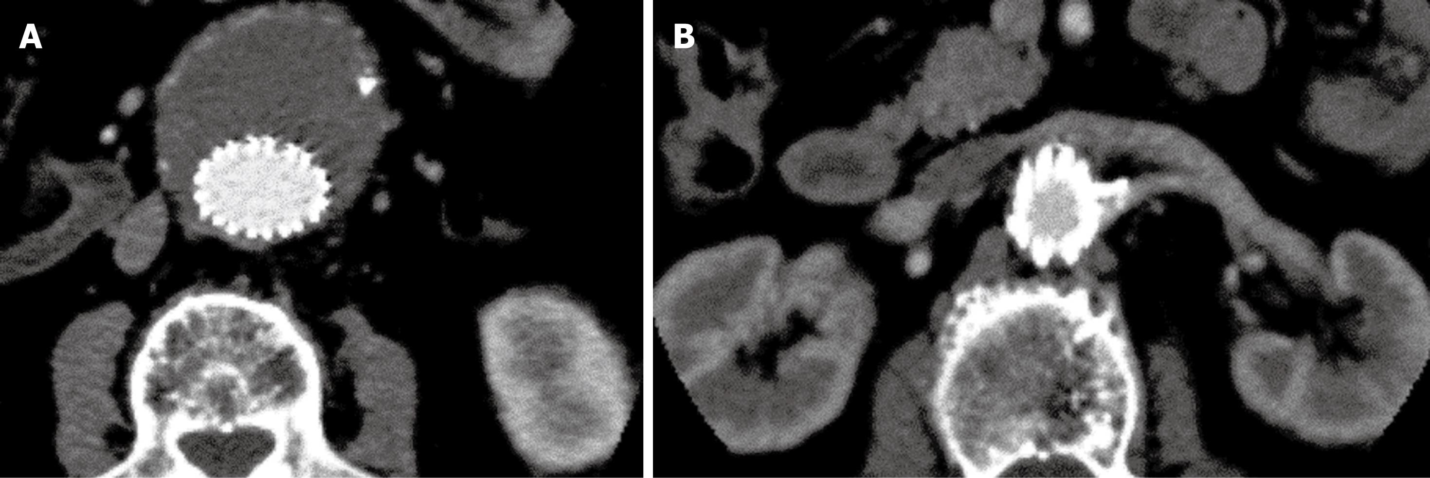
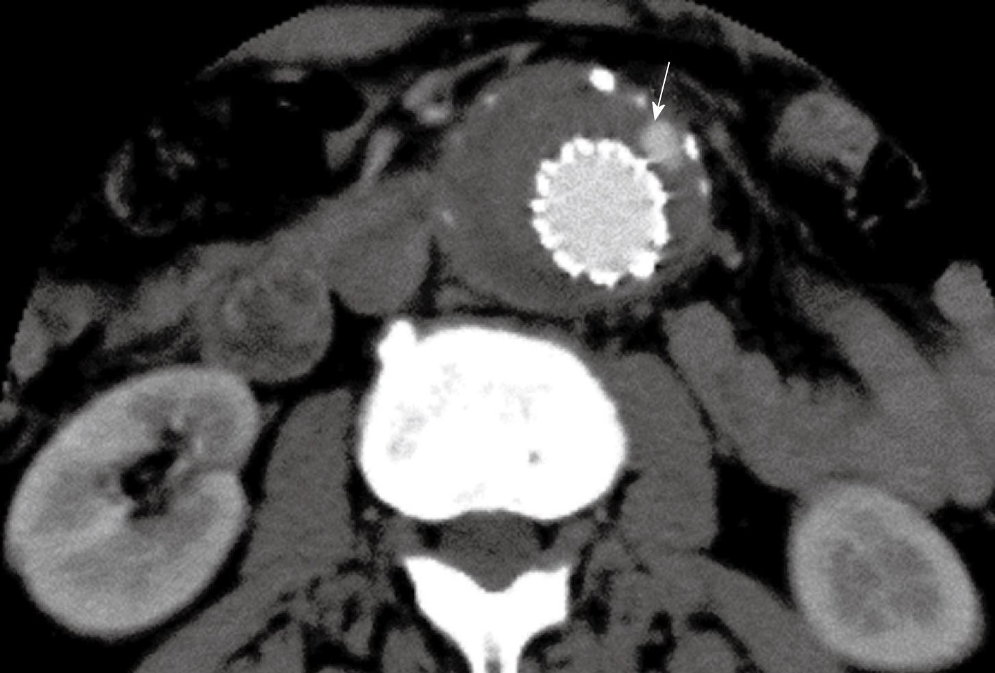
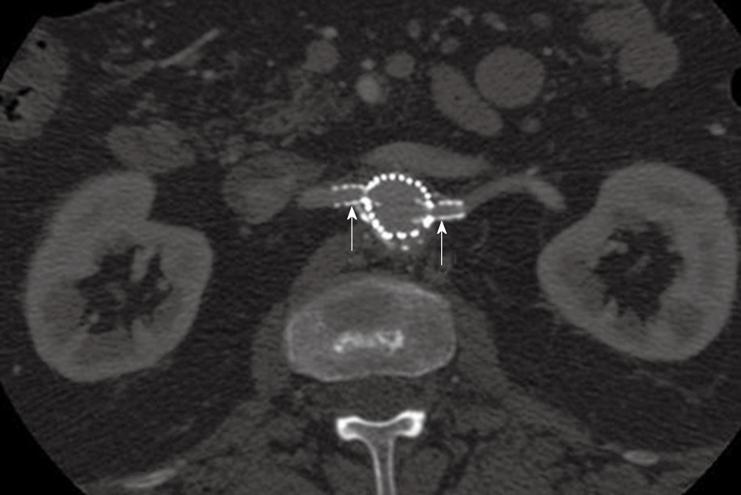
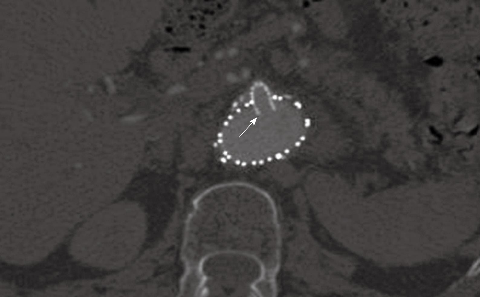
Conventional 2D axial imaging is the routine image visualization for follow-up of EVAR of AAA. Axial images are useful for detection and measurement of the aortic aneurysm diameter and extent, identification of the position of aortic stent grafts (Figure 2), detection of post-procedural complications such as endoleaks (Figure 3), patency of the stents inserted into the fenestrated vessels (Figure 4), and protrusion of the fenestrated stents into the aortic lumen (Figure 5). However, 2D axial images cannot provide the 3D relationship between stent grafts and aortic branches, which is the main limitation. Another limitation of the 2D axial images lies in the fact that 2D axial views do not provide accurate measurements of aneurysm length which is essential for pre-operative planning and aneurysm volume which is useful for follow-up. Traditionally, the preferred imaging method for surveillance of EVAR of AAA is CT angiography, which involves a series of maximal diameter measurements of the aneurysm at regular periods of follow-up, and determining whether the aneurysm is shrinking, enlarging, or remaining unchanged. This has been challenged by some studies which demonstrated the inaccuracy of diameter measurements[36-38]. Studies showed that volume measurement is superior to diameter measurement as it reflects all size changes of the aneurysm[37,38]. Thus, accurate evaluation of the aneurysm and stent grafts relative to the aortic branches cannot be assessed based only on 2D axial images. This is complemented by 2D or 3D reconstruction visualizations.
Figure 2 2D axial images in a patient treated with suprarenal stent graft.
The aneurysm was successfully excluded from the systemic circulation (A), and the suprarenal stent struts were placed above the left renal artery (B).
Figure 3 Contrast enhancement was present outside the stent graft but within the aneurysm sac indicating the endoleak (arrow) in a patient with abdominal aortic aneurysm (AAA) following suprarenal fixation of stent graft.
Figure 4 2D axial images show the small fenestrated stents inserted (arrows) into the bilateral renal arteries.
Figure 5 A large fenestrated stent was inserted into the superior mesenteric artery with an intraluminal protrusion (arrow).
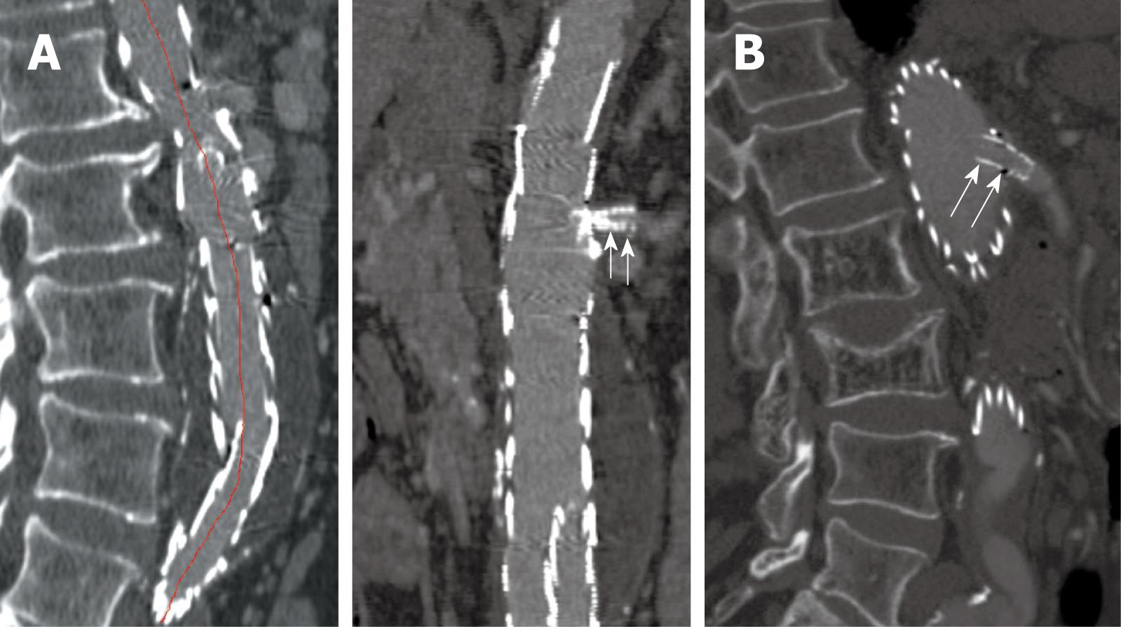
MPR is commonly used to demonstrate the stent grafts relative to the aortic branches through different views, such as coronal and sagittal reformation (Figure 6). Curved planar reformatted images are generated to look at tortuous vessels as these are useful for visualization of the stent grafts position inside the abdominal aorta, as well as the intraluminal portion of suprarenal and fenestrated stents (Figure 7). However, the intraluminal appearance of the suprarenal stent wires in terms of encroachment to the renal artery ostium and fenestrated stents cannot be clearly visualized on MPR views. Moreover, a series of MPR images are required for demonstration of the entire volume dataset as individual MPR views cannot provide all of the anatomical details, which is the main limitation of this visualization tool.
Figure 6 Sagittal multiplanar reformatted image shows the stent graft was placed below the celiac axis (short arrows) and SMA (long arrows).
Figure 7 Curved planar reformatted images are produced following the centreline of the abdominal aorta to demonstrate the fenestrated renal stent (arrows in A) and the intra-aortic portion of fenestrated stent deployed into the SMA (arrows in B).
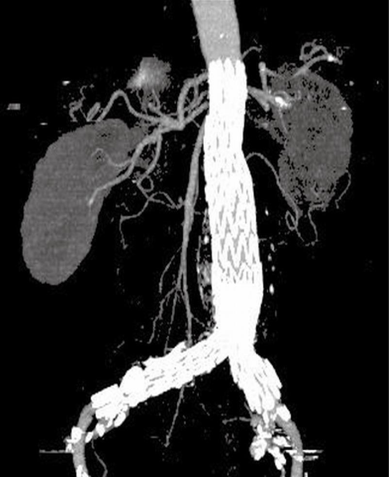
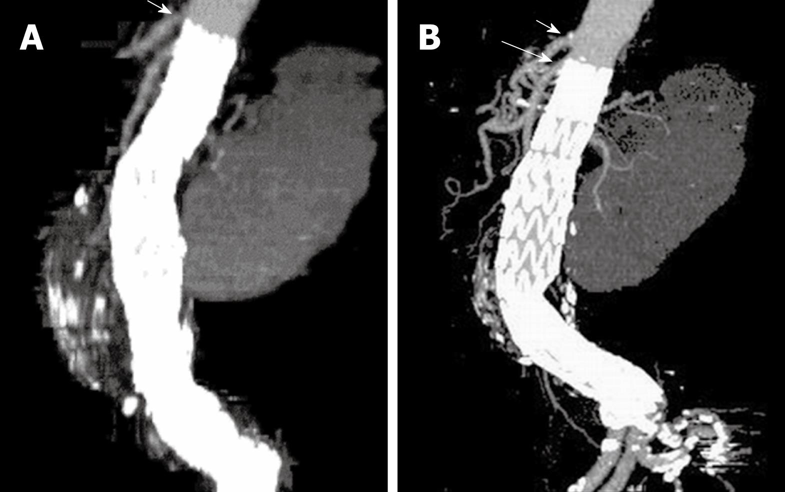
For CT angiography of aortic stent grafting, MIP is the most valuable visualization tool as it produces angiography-like images which clearly shows the high-density aortic stents and contrast-enhanced arterial branches (Figure 8). As a less invasive technique compared to invasive angiography, CT MIP was shown to be more accurate for measurement of stent graft migration than conventional 2D images[34] (Figure 9). CT MIP is a widespread useful visualization tool in aortic stent grafting, and its application has been significantly enhanced with the use of 3D software package that is currently available on the workstation of modern CT scanners.
Figure 8 Computed tomography (CT) coronal maximum-intensity projection (MIP) clearly demonstrates the high-density stent wires and contrast-enhanced blood vessels.
Figure 9 A stent graft migration of 10.
2 mm was noticed in a recent sagittal MIP image (B) in a patient treated with suprarenal stent graft 3 years ago (A). Short arrows indicate celiac axis, while long arrow refer to SMA.
3D VR AND VIE VISUALIZATION
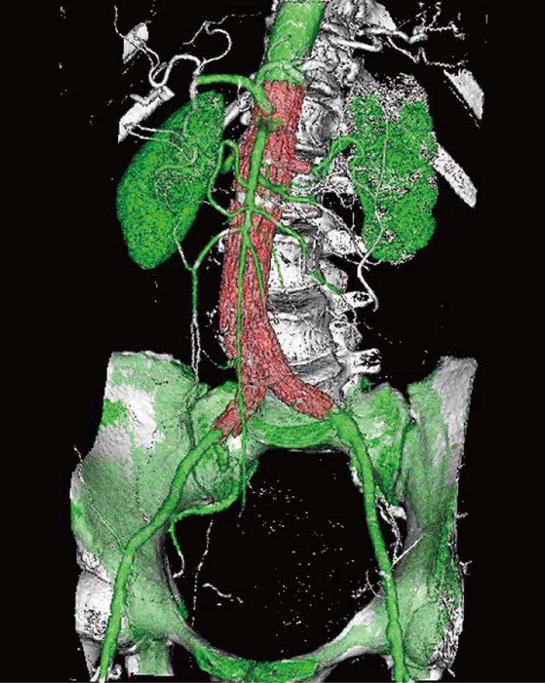
VR is an efficient visualization tool for showing the 3D relationship between stent grafts and arterial branches through use of the all of the information contained inside a volume dataset, thus enhancing readers’ understanding of the complex structures of stent grafts and arterial branches. In contrast to the above-mentioned 2D visualizations, VR can easily display various components in a single image with different colors coded to different anatomical structures (Figure 10). VR provides more information than MIP, since a realistic demonstration of the aortic stent grafts and aortic branches can be displayed in a three-dimensional format; thus better appreciation of the stent grafts in relation to the aortic branches can be obtained.
Figure 10 Volume rendering (VR) image demonstrates the 3D relationship between fenestrated renal stents (red color) and aortic branches (green color).
Bones are coded with white color.
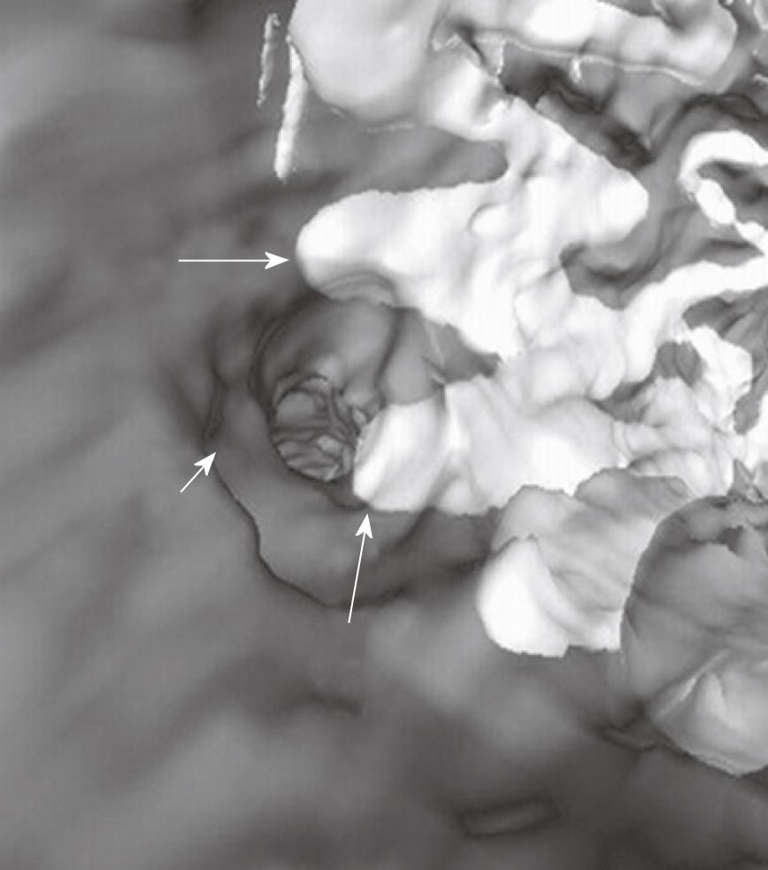
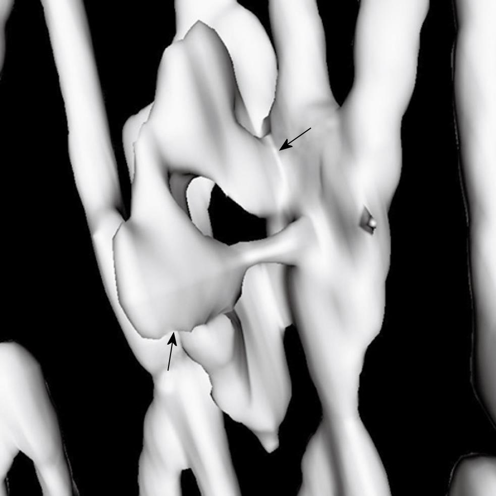
As part of the VR visualization, VIE provides unique information of the intraluminal appearance of the artery wall and aortic stents. Our previous studies showed that VIE provides additional information about suprarenal stents encroachment to the renal artery ostium in terms of the configuration of stent wires and number of stent wires crossing the renal ostium (Figure 11)[31-34]. For fenestrated stent grafting of AAA, VIE is also able to demonstrate the intraluminal configuration and the intra-aortic protrusion of the fenestrated stents (Figure 12). This includes the normal appearance of fenestrated stents, as well as deformity or occlusion of the fenestrated stents resulting from the inappropriate fenestrated procedures (Figure 13)[30,35]. In comparison to conventional 2D visualizations, VIE offers valuable information about suprarenal and fenestrated repair since it demonstrates the number of stent wires crossing the renal ostium, confirms the patency of fenestrated vessels, and performs accurate measurement of the intraluminal portion of the fenestrated stents. These details are believed useful for patient follow-up.
Figure 11 Virtual intravascular endoscopy (VIE) shows the left renal ostium (short arrow) was peripherally crossed by two suprarenal stent struts (long arrows).
Figure 12 VIE views demonstrate the intraluminal appearance of fenestrated renal stent as circular configuration (A).
In addition, the intraluminal portion of the fenestrated stent can be visualised and measured on VIE (arrows in B).
Figure 13 Deformed fenestrated renal stent with irregular appearance is displayed on VIE image (arrows).
INTERFERENCE OF AORTIC STENTS WITH RENAL HEMODYNAMICS
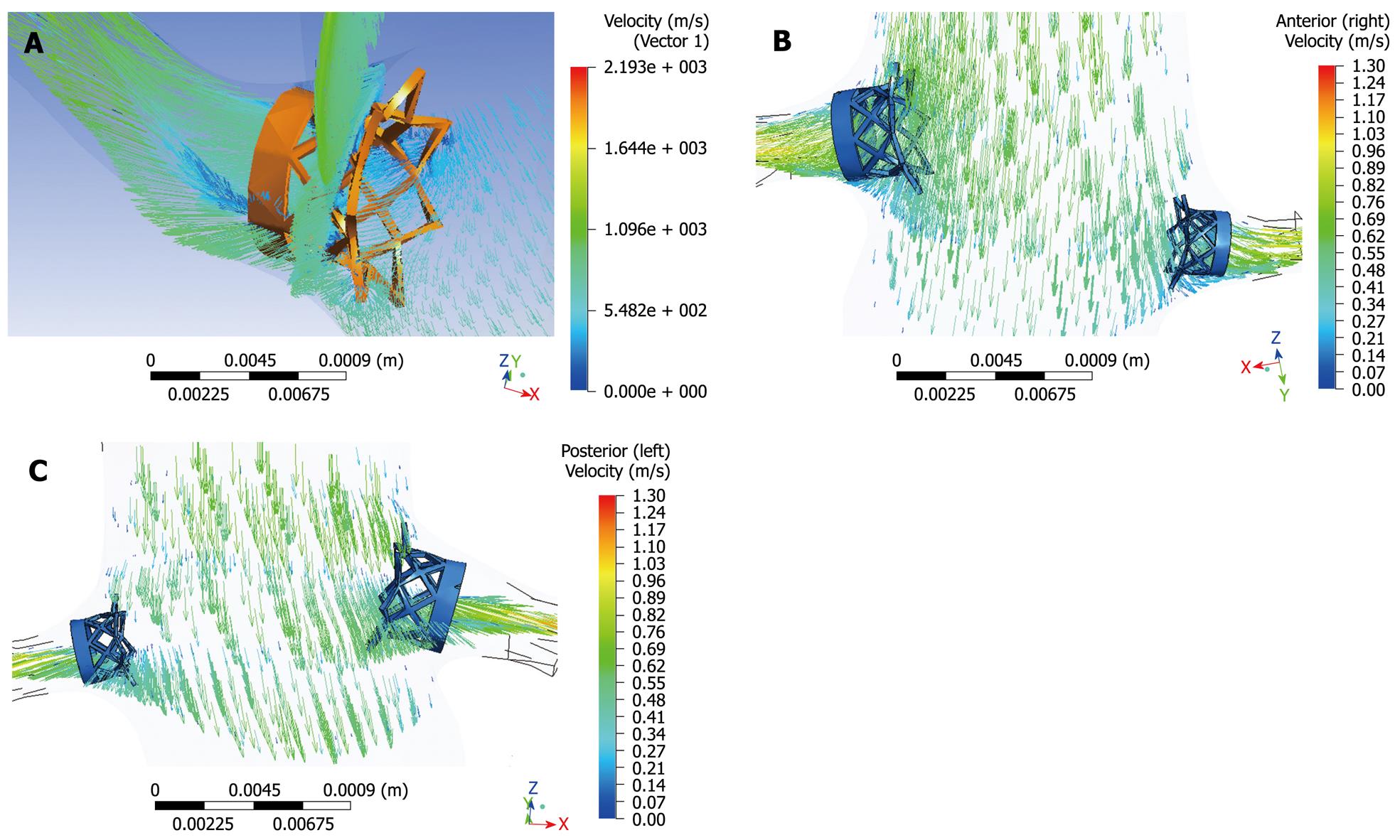
The deployment of a complex multi-component endovascular device in the abdominal aorta is likely to change the local hemodynamics and adversely affects the long-term performance of the device. Researchers studied the fluid-stent graft interaction based on AAA models with a focus on infrarenal fixation of stent grafts[39-41]. Our previous experiments based on realistic aorta models with variable configurations of suprarenal stent wires crossing the renal artery ostium showed that multiple wire configuration leads to a significant decrease in flow velocity to the renal artery, while single wire crossing has a minimal effect on the renal flow changes (Figure 14)[42]. For fenestrated stent grafting, the hemodynamic analysis showed that the interference of fenestrated renal stents with the renal blood flow is minimal and insignificant, so this indicates the safety of deploying the fenestrated renal stents inside the renal arteries (Figure 15)[43]. However, wall shear stress at the renal arteries was reduced after implantation of the fenestrated renal stents, thus this could lead to a potential risk of thrombus formation or stenosis at the renal arteries. Further studies with simulation of different stent wire thicknesses or variable lengths of stent protrusion are necessary to investigate the hemodynamic effects of endovascular stent graft repair of AAA.
Figure 14 Computational fluid dynamic analysis of the interference of suprarenal stent struts with renal blood flow shows the flow velocity calculated in a realistic aorta model without placement of suprarenal stent struts (A), with simulated stent wire thickness of 0.
4 mm (B), 1.0 mm (C) and 2.0 mm (D). The laminar flow pattern from pre-stent grafting was found to change to turbulent with simulated stent struts across the renal arteries, with flow velocity decreased up to 30% when the wire thickness increased to 2.0 mm.
Figure 15 Computational fluid dynamic analysis of the interference of fenestrated renal stent with renal flow was performed with a simulated renal stent inserted into the renal arteries based on an aorta model (A).
Flow velocity was not significantly affected after placement of fenestrated renal stents, although flow recirculation was observed at the proximal portion of the renal arteries (B, C).
FUTURE DIRECTIONS
Since the main concern associated with EVAR of AAA is the patency of renal arteries essential to maintain renal perfusion, future developments of endovascular stent grafts lie in the long-term safety and effects on renal function. This can be achieved through technical modifications of the stent grafts, such as bioengineering of the stent grafts to reduce the proliferation on the stent surface once deployed inside the aorta, or production of drug-eluting stents for fenestrated renal stents[44,45]. In addition to these technical developments, imaging follow-up is another issue that needs to be drawn to endovascular specialists’ attention, as patients treated with aortic stent grafts are routinely followed for a long time, thus selection of appropriate imaging modalities is of paramount importance for both monitoring of the success of the procedure and detection of complications.
Helical CT angiography has been widely recognized as the method of choice for follow-up of EVAR of AAA due to its accuracy for measurement of the aneurysm and sensitivity for detection of endoleaks[11-13]. However, CT suffers from the issue of radiation exposure to patients, which is the main disadvantage. Follow-up of patients after EVAR requires multiple examinations at 1, 6 and 12 mo post-procedure, and typically requires the use of thin slices and multiple phase examinations. Thus, patients undergoing EVAR are at potential risk for excessively being exposed to radiation[46]. Optimization of CT scanning protocol is one of the effective strategies to reduce radiation dose. Iezzi et al[46] in their study reported that an overall radiation dose reduction of 74% was achieved with low dose protocol when compared to the standard dose protocol, while maintaining image quality. A recent study investigating the radiation exposure during EVAR of AAA concluded that the mean effective dose of CT angiography was 27 mSv, and the entrance skin dose exceeded the threshold value in 29% of patients[47]. This indicates the trend to move from CT follow-up to ultrasound surveillance[48-50], which is another effective approach to reduce radiation dose, since lifelong surveillance is necessary after EVAR. Several studies reported excellent results of ultrasound in the follow-up of EVAR of AAA when compared to CT angiography[16-18,48,49].
Traditional imaging-based follow-up of AAA after EVAR restricted to the detection of endoleaks (the most common complication of EVAR) and changes in AAA morphology have proved unreliable in preventing aneurysm rupture. Pressure measurements of the aneurysm sac are increasingly being recognized as the most accurate indication of AAA exclusion[51-53]. Attempts have been made at assessment of EVAR by intra-aneurysm sac pressure measurements through in vitro and in vivo studies[51-53]. These studies showed that high intra-aneurysm sac pressure is associated with AAA enlargement and low pressure with shrinkage. Imaging alone requires at least two time interval examinations to determine the trend or treatment outcomes of EVAR. Pressure measurements allow immediate reassurance or indication to intervene. Although it may only apply to few now, pressure measurement is heralded for general use and will provide a scientific basis for the management of common complications such as endoleaks[21].
CONCLUSION
There is no doubt that EVAR will continue to play an increasing role in the treatment of patients with AAA. While its benefits have been widely recognized by clinical practice and thousands of cases are performed every year, the long-term durability is yet to be confirmed. Medical imaging modalities play an essential role in both planning and post-operative follow-up. CT is the preferred imaging modality for following patients treated with endovascular stent grafts; however, ultrasound is being increasingly used to monitor the treatment outcomes at regular follow-up as it does not involve ionizing radiation and its diagnostic accuracy for detection of endoleaks is comparable to CT imaging. Although still under development, pressure measurement is destined for general use and will provide a scientific basis for monitoring treatment outcomes of EVAR and the management of complications such as type II endoleaks. Technical improvements are required to ensure the long-term safety of deploying the stent grafts inside the abdominal aorta and artery branches.
Peer reviewers: Fehmi Kaçmaz, MD, Department of Cardiology, Mesa Hospital, Ozel Mesa Hastanesi, Yasam Cad, No: 5 Sogutozu, 06510 Ankara, Turkey; Ramachandran Prabhakar, PhD, Department of Radiation Oncology, Institute Rotary Cancer Hospital, All India Institute of Medical Sciences, New Delhi 110 029, India
S- Editor Wang JL L- Editor O’Neill M E- Editor Zheng XM


