Copyright
©The Author(s) 2016.
World J Radiol. May 28, 2016; 8(5): 518-529
Published online May 28, 2016. doi: 10.4329/wjr.v8.i5.518
Published online May 28, 2016. doi: 10.4329/wjr.v8.i5.518
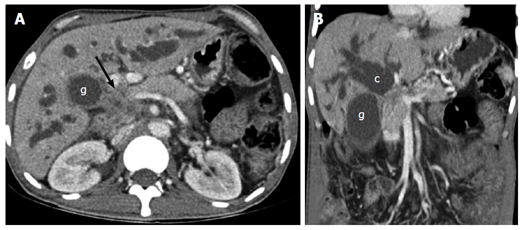
Figure 1 Axial (A) and coronal (B) contrast enhanced computed tomography scan of a patient with carcinoma of gall bladder showing mass (arrow) arising from the neck of gall bladder (g) involving common hepatic duct with patent primary biliary confluence (c).
Figure 2 Arterial (A) and venous (B) phase axial and venous phase oblique coronal (C) computed tomography scan images of hilar cholangiocarcinoma showing soft tissue mass involving the common hepatic duct (black arrow), blocking the primary biliary confluence (white arrow).
Figure 3 Hilar cholangiocarcinoma.
A: Axial T2-weighted MR image showing isointense mass involving the primary biliary confluence (arrow) causing biliary dilatation; B: MRCP showing dilated ducts with blocked primary confluence (arrow); C: Axial contrast enhanced T1-weighted image in delayed phase showing enhancing mass in the primary biliary confluence (arrow). MR: Magnetic resonance; MRCP: Magnetic resonance cholangiopancreatography.
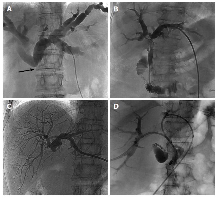
Figure 4 Cholangiograms.
A: Initial cholangiogram after puncture showing block below the primary biliary confluence (arrow); B: Internal/external drainage by ring biliary catheter; C: External drainage by a pig tail catheter; D: Internal/external drainages of both lobes with ring biliary catheter in obstruction of primary biliary confluence.
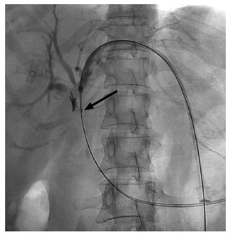
Figure 5 Brush biopsy needle (arrow) seen inserted through the sheath to obtain sample from the mass at the level of obstruction.
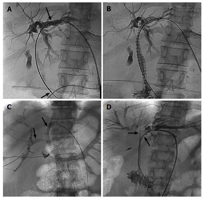
Figure 6 Biliary stenting.
A: Positioning of the metallic stent with markers (arrows) for optimal deployment; B: Expanded metallic stent after deployment across the stricture; C: Bilobar metallic stent placement (arrows); D: Placement of ring biliary catheter by the side of blocked plastic stent after failed endoscopic exchange.
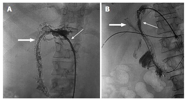
Figure 7 Stent block.
A: Ring biliary catheter (arrow) placed through a blocked metallic stent (block arrow) due to disease progression; B: Second metallic stent (arrow) placed through the initial blocked right sided metallic stent (block arrow).
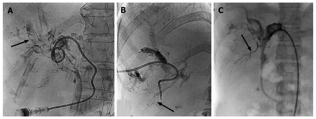
Figure 8 Hemobilia.
A: Cholangiogram in a case of hemobilia shows multiple filling defects (arrow) within the biliary ducts; B: Cholangiogram showing opacification of branches of portal vein (arrow) suggesting bilio-venous fistula; C: Cholangiogram showing opacification of branches of right hepatic artery (arrow).
Figure 9 Catheter related complications.
A: Cholangiogram showing pericatheter leak (black arrow) due to proximally dislodged ring biliary catheter (white arrow); B: Dislodged external drainage catheter (arrow) with only tip in the left hepatic duct; C: Fracture (arrow) of ring biliary catheter.
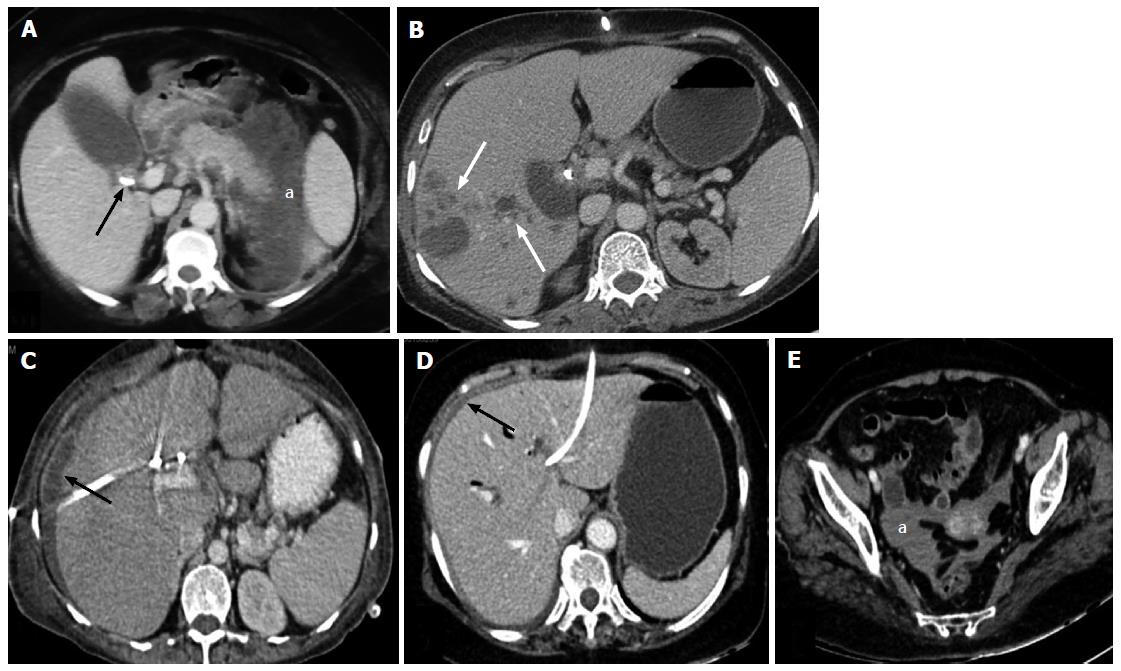
Figure 10 Complications.
A: Axial contrast enhanced CT scan showing bulky pancreas with peripancreatic necrotic collection (a) developing after PTBD in a patient of carcinoma of gall bladder (arrow); B: Axial contrast enhanced CT scan after PTBD showing multiple abscesses in right lobe of liver (arrows); C: Axial CT scan after PTBD showing perihepatic bilioma (arrow); D and E: Axial CT scans after PTBD showing hyperdense fluid in perihepatic (arrow) region and pelvis (a) suggesting hemoperitoneum. CT: Computed tomography; PTBD: Percutaneous transhepatic biliary drainage.
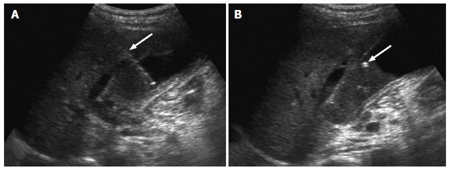
Figure 11 Cholecystostomy.
Ultrasonography images showing transhepatic puncturing of gall bladder (arrow in A) and placement of pigtail catheter (arrow in B).
- Citation: Madhusudhan KS, Gamanagatti S, Srivastava DN, Gupta AK. Radiological interventions in malignant biliary obstruction. World J Radiol 2016; 8(5): 518-529
- URL: https://www.wjgnet.com/1949-8470/full/v8/i5/518.htm
- DOI: https://dx.doi.org/10.4329/wjr.v8.i5.518


