Copyright
©The Author(s) 2015.
World J Radiol. Dec 28, 2015; 7(12): 484-493
Published online Dec 28, 2015. doi: 10.4329/wjr.v7.i12.484
Published online Dec 28, 2015. doi: 10.4329/wjr.v7.i12.484
Figure 1 Multiplanar and rendering modes of the uterus.
Multiplanar reconstructions from 3D ultrasound show a normal uterus in sagittal (A), transverse (B) and true coronal (C) planes. Surface rendering reconstructed image in a coronal plane of the uterus demonstrating a normal uterine fundal contour (D). 3D: Three-dimensional.
Figure 2 Examples of post-processing functions include surface render and volume contrast imaging.
A: Three-dimensional (3D) ultrasound with surface rendering of a normal uterus in the coronal plane; B: 3D ultrasound with volume contrast imaging of the same uterus.
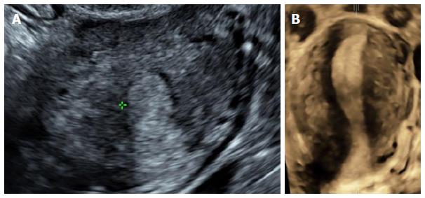
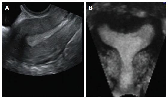
Figure 4 Unicornuate uterus with no rudimentary horn.
A: Transverse 2D ultrasound image shows a single endometrial cavity; B: Coronal 3D (with VCI) ultrasound image of the unicornuate uterus showing a single uterine horn with no divergence of the endometrium towards both ostia and absence of a rudimentary horn. 3D: Three-dimensional; 2D: Two-dimensional; VCI: Volume contrast imaging.
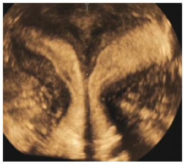
Figure 5 Uterine didelphys.
Coronal 3D ultrasound image of a didelphys uterus show two widely divergent uterine horns separated by a deep external cleft ≥ 1 cm. 3D: Three-dimensional.
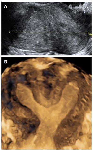
Figure 6 Bicornuate uterus.
A: Transverse 2D ultrasound image of a bicornuate uterus showing the presence of 2 endometrial cavities; B: Coronal 3D ultrasound image of a bicornuate uterus showing external cleft ≥ 1 cm and internal indentation ≥ 1.5 cm. Note the presence of fundal soft tissue separating the 2 uterine cavities, which distinguishes it from uterine didelphys. 3D: Three-dimensional; 2D: Two-dimensional.
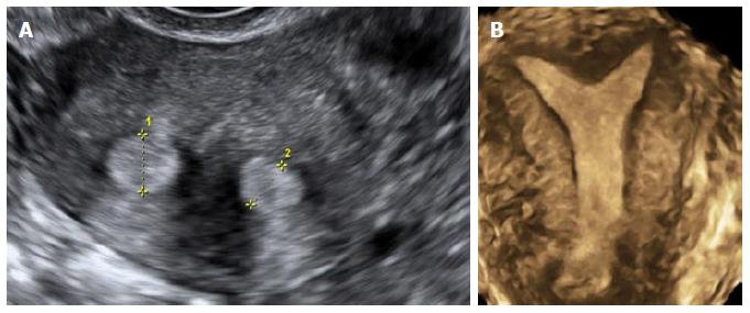
Figure 7 Septate uterus.
A: Transverse 2D ultrasound image of a septate uterus showing the presence of 2 endometrial cavities; B: Coronal 3D ultrasound image of a partial septate uterus with the external cleft < 1 cm but internal indentation > 1.5 cm. 3D: Three-dimensional; 2D: Two-dimensional.
Figure 8 Arcuate uterus.
A: Sagittal 2D ultrasound image of an arcuate uterus; B: Coronal 3D ultrasound image of an arcuate uterus with a smooth external contour and internal indentation ≥ 1 cm but ≤ 1.5 cm. 3D: Three-dimensional; 2D: Two-dimensional.
Figure 9 Malposition of an intrauterine device.
Sagittal (A) and transverse (B) 2D ultrasound image showing the shaft within the endometrial cavity; C: Coronal 3D ultrasound image showing the IUD lying inverted with both arms embedded within the myometrium. 3D: Three-dimensional; 2D: Two-dimensional; IUD: Intrauterine device.
Figure 10 Intramural fibroid with an intrauterine pregnancy.
A: Transverse 2D ultrasound image showing an intrauterine gestation sac positioned towards the left endometrial cavity; B: 3D coronal ultrasound image showing an intramural fibroid distorting the endometrial cavity, thus deviating the intrauterine pregnancy towards the left endometrial cavity. 3D: Three-dimensional; 2D: Two-dimensional.
Figure 11 Endometrial polyp.
A: Sagittal 2D ultrasound image of an endometrial polyp as identified by a vascular pedicle; B: Transverse 2D ultrasound image of the echogenic endometrial polyp; C: 3D coronal (VCI) ultrasound image showing the endometrial polyp better delineated as an echogenic mass. 3D: Three-dimensional; 2D: Two-dimensional; VCI: Volume contrast imaging.
Figure 12 Adenomyosis with loss of the endometrial-myometrial junction.
Sagittal (A) and transverse (B) 2D ultrasound images show the classic “venetian blind” shadowing of diffuse adenomyosis with loss of the endometrial-myometrial junction; B: 3D coronal ultrasound image (with VCI) showing the irregular endometrial-myometrial junction. Note the left lateral intramural fibroid. 3D: Three-dimensional; 2D: Two-dimensional; VCI: Volume contrast imaging.
Figure 13 Saline infusion sonohysterography.
A: 3D (VCI) A-plane image showing a thickened polypoid anterior endometrium upon distension with saline; B: 3D coronal image showing delineation of the polypoid endometrium on SIS. SIS: Saline infusion sonohysterography; 3D: Three-dimensional; VCI: Volume contrast imaging.
- Citation: Wong L, White N, Ramkrishna J, Júnior EA, Meagher S, Costa FDS. Three-dimensional imaging of the uterus: The value of the coronal plane. World J Radiol 2015; 7(12): 484-493
- URL: https://www.wjgnet.com/1949-8470/full/v7/i12/484.htm
- DOI: https://dx.doi.org/10.4329/wjr.v7.i12.484


