Copyright
©The Author(s) 2015.
World J Radiol. Dec 28, 2015; 7(12): 459-474
Published online Dec 28, 2015. doi: 10.4329/wjr.v7.i12.459
Published online Dec 28, 2015. doi: 10.4329/wjr.v7.i12.459
Figure 1 Normal arway.
Axial image at the level of arch of aorta (A) shows a typical inverted U shaped trachea with thin fibromuscular membrane in posterior portion lying between open ends of tracheal cartilages. Axial image (B) at the level of carina (arrow) shows dichotomous branching of trachea at its distal end into right and left main bronchi. Coronal MPR image (C) shows trachea and mainstem bronchi as uniform tubular structures in midline within the mediastinum. Coronal reconstructed MinIP image (D) shows trachea and its bronchial branches as tubular air containing structures continuous from thoracic inlet till its divisions into the lung parenchyma. Volume rendered image (E) is the external rendered image showing 3-dimensional display of external surface of the airway and lung parenchyma. MPR: Multiplanar reformation; MinIP: Minimum intensity projection.
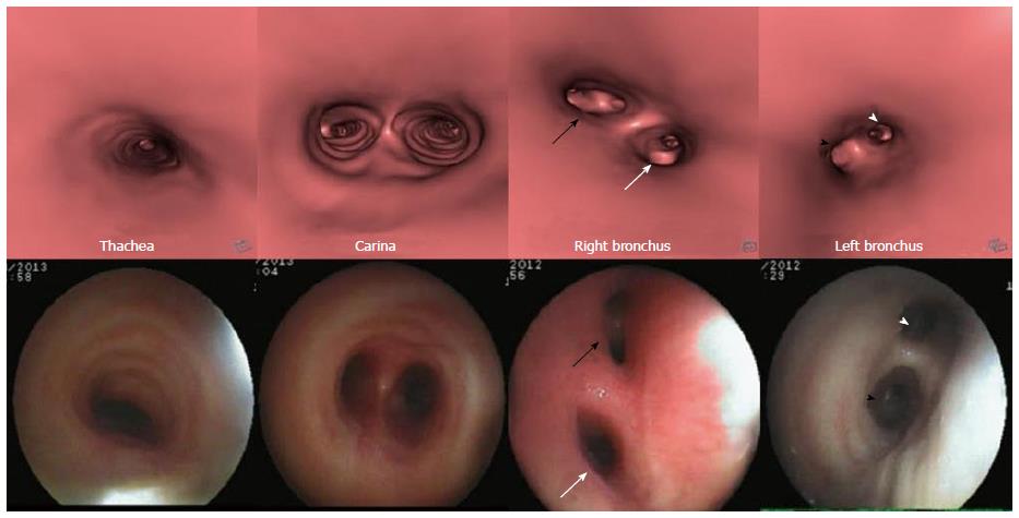
Figure 2 Virtual bronchoscopy of normal airway.
Virtual bronchoscopy or internal rendered images reconstructed using dedicated “fly through” software at the level of trachea, carina, right and left main bronchus (top row) with corresponding appearance on fiberoptic bronchoscopy (bottom row). The division of right bronchus into upper lobe (white arrow) and bronchus intermedius (black arrow) and division of left main bronchus into upper (black arrowhead) and lower lobe bronchus (white arrowhead) is seen.
Figure 3 Squamous cell lung carcinoma.
Contrast enhanced axial (A) and coronal MPR (B) images show enhancing soft tissue mass in right perihilar region with intraluminal extension of growth into the right mainstem bronchus and lower trachea (arrow). Coronal MinIP image (C) shows attenuation of right mainstem bronchus with a polypoidal growth extending into lower trachea (arrow). Virtual bronchoscopy (D) shows an irregular polypoidal intraluminal mass in lower trachea (arrow). MPR: Multiplanar reformation; MinIP: Minimum intensity projection.
Figure 4 Small cell lung cancer.
Axial (A) and coronal MPR (B) images show heterogeneously enhancing mass lesion encasing and attenuating left main bronchus and its lower division with mediastinal invasion and associated collapse-consolidation of left lower lobe. Coronal MinIP image (C) shows attenuated left main bronchus (arrow). MPR: Multiplanar reformation; MinIP: Minimum intensity projection.
Figure 5 Squamous cell carcinoma of trachea.
Axial (A) and coronal MPR (B) images show eccentric soft tissue mass with irregular surface involving trachea (arrow in B) with mediastinal extension (arrow in A). Coronal MinIP (C) shows partial attenuation of mid tracheal lumen involving a length of 3.19 cm (arrow). Virtual bronchoscopy (D) shows this mass lesion as irregular intraluminal growth along the right wall of trachea causing tracheal luminal narrowing. MPR: Multiplanar reformation; MinIP: Minimum intensity projection.
Figure 6 Adenoid cystic carcinoma of trachea.
Axial (A) and coronal MPR (B) images show polypoidal mass with smooth outline within the trachea in subglottic region causing near complete attenuation of the airway (arrow). Virtual bronchoscopy (C) shows intraluminal smooth mass within trachea similar to that seen on conventional bronchoscopy (D). MPR: Multiplanar reformation.
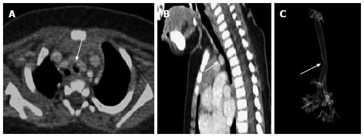
Figure 7 Respiratory papilloma.
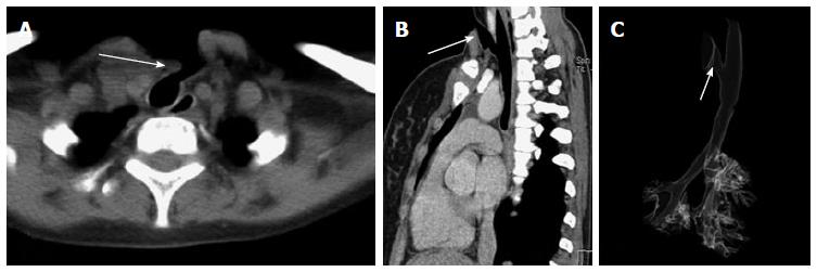
Axial (A) and sagittal MPR (B) images show a smooth polypoidal soft tissue mass arising from the postero-lateral wall of trachea (arrow). Virtual bronchoscopy (C) shows the intraluminal mass lesion with smooth surface (arrow). MPR: Multiplanar reformation.
Figure 8 Post intubation tracheal stenosis.
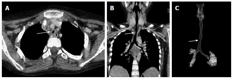
Axial (A), coronal MPR (B) and VRT (C) images show a focal short segment concentric narrowing of tracheal lumen giving an “hourglass” configuration better appreciated on coronal images. MPR: Multiplanar reformation; VRT: Volume rendering technique.
Figure 9 Tracheal membrane.
Sagittal MPR (A) and sagittal MinIP (B) images show a partially occluding thin membrane in subglottic airway (arrow). Note made of tracheostomy tube insitu. Virtual bronchoscopy (C) shows circumferential membrane causing narrowing of airway lumen with similar finding confirmed on fiberoptic bronchoscopy. MPR: Multiplanar reformation; MinIP: Minimum intensity projection.
Figure 10 Post intubation mucosal synechiae.
Sagittal MPR (A) and MinIP (B) images show thin membrane like adhesions within the airway at subglottic (black arrow) and upper tracheal (red arrow) levels extending across the airway lumen and compromising its patency suggestive of synechiae formation. The corresponding appearance of these synechiae are very well demonstrated on virtual bronchoscopy (C and D). MPR: Multiplanar reformation; MinIP: Minimum intensity projection.
Figure 11 Post tracheostomy tracheo-cutaneous fistula.
Axial (A) and oblique sagittal MPR (B) images show the fistula as an abnormal tract extending from antero-lateral wall of upper trachea to the skin surface (arrow). This fistulous tract is very well demonstrated on VRT image (C, arrow). MPR: Multiplanar reformation; VRT: Volume rendering technique.
Figure 12 Foreign body aspiration.
Coronal MPR images of thorax in lung settings (A) and mediastinal window settings (B) reveal soft tissue density attenuating left main bronchus (arrow) with associated hyperinflation of left lung. Virtual bronchoscopy (C) shows obstruction of left main bronchus with lobulated surface confirmed to be endobronchial foreign body (arrow) on conventional bronchoscopy (D). MPR: Multiplanar reformation.
Figure 13 Chronic foreign body aspiration.
Axial (A) and oblique coronal MPR (B) images reveal soft tissue density partially occluding the left main bronchus (arrow) with consolidation of left lung and associated bronchiectatic changes. Coronal MinIP image (C) shows attenuation of left main bronchus (arrow) with collapse of left lung. Endobronchial foreign body within left main bronchus was confirmed to be a small piece of plastic on conventional bronchoscopy (D). MPR: Multiplanar reformation; MinIP: Minimum intensity projection.
Figure 14 Broncholith.
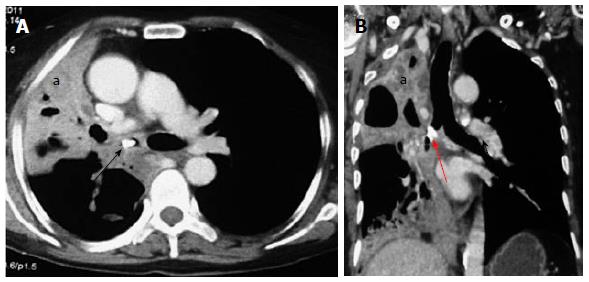
Axial (A) and coronal MPR (B) images show a hyperdense calcific density within the right main bronchus (arrow) with collapse-consolidation and bronchiectasis in the right lung (a). MPR: multiplanar reformation.
Figure 15 Airway wall pathology.
Traumatic tracheal rent-Axial (A) and oblique coronal MinIP (B) images show a focal air containing outpouching at the level of carina in midline projecting antero-inferiorly (arrows). Virtual bronchoscopy (C) shows a focal defect within the wall of trachea at the level of carina (arrow). Note made of marked subcutaneous emphysema (arrowhead in B ). Tracheo-esophageal fistula-sagittal MPR image (D) of another case shows a thin faint air containing tract (arrow) extending from esophagus (e) to trachea (t). MPR: Multiplanar reformation; MinIP: Minimum intensity projection.
Figure 16 Double aortic arch.
Serial axial images (A-D) of thorax (in caudo-cranial direction) reveal 2 aortic arches encircling and compressing trachea (t) and esophagus (e). Ipsilateral subclavian and common carotid arteries arise from each arch giving a characteristic “4-vessel sign” (arrows in D).
Figure 17 Innominate artery compression.
Contrast enhanced axial (A) and sagittal MPR (B) images show extraluminal compression of trachea by anomalous course of innominate artery winding around the anterior wall of trachea (arrow). 3D VRT image (C) shows smooth indentation on the tracheal air column (arrow). MPR: Multiplanar reformation; VRT: Volume rendering technique.
Figure 18 Left pulmonary artery sling.
Contrast enhanced axial (A) and sagittal MPR (B) images reveal aberrant course of left pulmonary artery between trachea and esophagus (arrow) causing tracheal compression and vascular indentation on esophagus. Note made of left superior vena cava (a). Virtual bronchoscopy (C) shows an eccentric impression causing focal narrowing of the tracheal lumen (arrow). MPR: Multiplanar reformation.
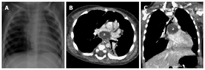
Figure 19 Subcarinal bronchogenic cyst.
Frontal radiograph of chest (A) reveals mediastinal widening (arrow). Contrast enhanced axial (B) and coronal MPR (C) images reveal well defined non-enhancing homogenous fluid attenuation lesion in subcarinal location (a) narrowing the bronchial divisions with resultant subsegmental atelectasis in left lower lobe. MPR: Multiplanar reformation.
Figure 20 Paratracheal bronchogenic cyst.
Coronal MPR image (A) shows large well defined non enhancing fluid attenuation lesion (a) in right paratracheal location with mass effect on adjacent trachea causing tracheal luminal attenuation (arrow). Coronal MinIP (B) and VRT (C) images show extrinsic mass effect on the airway (arrow) and right lung. Virtual bronchoscopy (D) clearly demonstrates the smooth extraluminal compression along the right wall of trachea causing luminal compromise. MPR: multiplanar reformation; MinIP: Minimum intensity projection; VRT: Volume rendering technique.
Figure 21 Bronchogenic cyst.
Frontal radiograph of chest (A) shows a well-defined air filled cystic lesion in the retrocardiac location. Axial (B), coronal (C) and sagittal (D) MPR images show a large well defined homogenous air containing lesion (arrow) with carinal widening. The lesion is causing partial airway obstruction seen as air trapping in right middle lobe (a). MPR: Multiplanar reformation.
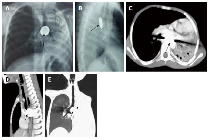
Figure 22 Impacted esophageal foreign body compressing airway.
Frontal (A) and lateral (B) radiographs of chest reveal a well-defined round radio-opaque foreign body in the esophagus at the level of carina (arrows) with associated volume loss of left lung. Contrast enhanced axial (C) and sagittal (D) MPR images show a hyperdense foreign body giving streak artefacts impacted within the esophagus (arrow). Coronal MinIP image (E) shows near complete occlusion of left main bronchus (arrowhead) by the impacted esophageal foreign body (arrow) with collapse of left lung. MPR: Multiplanar reformation; MinIP: Minimum intensity projection.
Figure 23 Enlarged tubercular lymph nodes compressing airway.
Contrast enhanced axial (A) and coronal MPR (B) images show enlarged necrotic lymph nodal mass (n) in subcarinal station causing carinal widening and compression of left main bronchus (arrow). VRT (C) and virtual bronchoscopy (D) images also show compression of left main bronchus (arrow). MPR: Multiplanar reformation; VRT: Volume rendering technique.
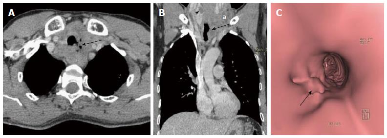
Figure 24 Paratracheal erosive malignant lymph nodes.
Contrast enhanced axial (A) and coronal MPR (B) images show enlarged necrotic paratracheal lymph nodes eroding adjacent airway and showing foci of air within. There is a hypodense mass lesion (arrowhead in B) in right lobe of thyroid (patient was a known case of metastatic papillary thyroid carcinoma). Enlarged necrotic left lower jugular lymph nodes (a in B) also noted. Virtual bronchoscopy (C) shows focal area of irregularity along left lateral tracheal wall (arrow). MPR: Multiplanar reformation.
Figure 25 Saber-sheath trachea.
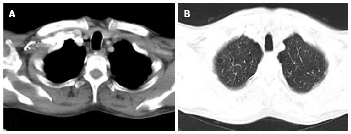
In a 70-year old male with chronic obstructive pulmonary disease, axial images of thorax in mediastinal (A) and lung (B) window settings show increase in antero-posterior diameter of the trachea with narrowing of the transverse diameter. The sagittal to transverse diameter ratio measured 2.13:1.
Figure 26 Mounier Kuhn syndrome.
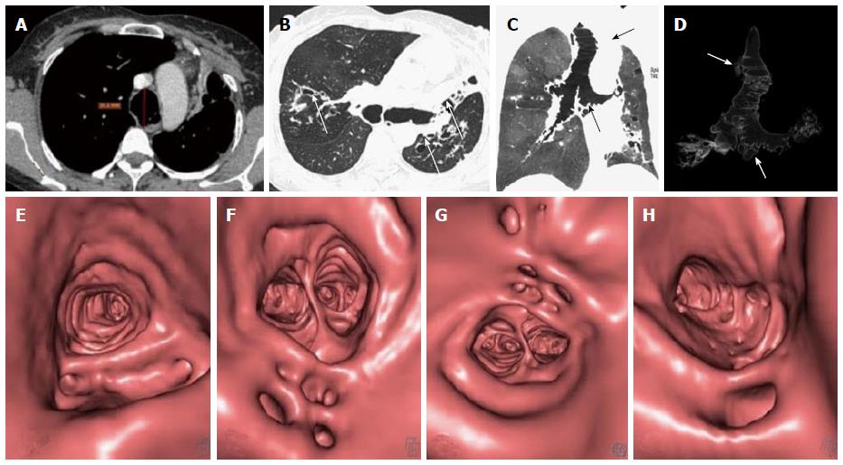
Axial images (A and B) show dilated trachea-AP diameter 3.6 cm at level of aortic arch (A) with dilated bronchi (B) and diverticula formation. Bronchiectasis is seen in bilateral upper and left lower lobes with collapse of lingula (arrow in B). Coronal MinIP (C) and VRT (D) images show tracheo-bronchomegaly with diffuse diverticulosis (arrows). Virtual bronchoscopy also shows diffusely scattered defects in the walls of upper trachea (E), carina (F), right (G) and left (H) main bronchi. MinIP: Minimum intensity projection; VRT: Volume rendering technique.
Figure 27 Tracheobronchopathia osteochondrodisplastica.
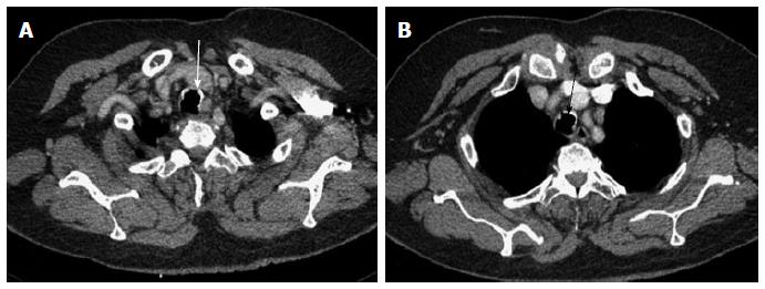
Axial images of thorax (A and B) show irregular nodular thickening with foci of calcification involving the anterior and lateral walls of trachea (arrows). There is characteristic sparing of the posterior tracheal membrane.
Figure 28 Displaced bronchus.
Case 1: Coronal MinIP (A) and VRT (B) images show anomalous origin of right upper lobe bronchus from trachea-“Pig bronchus/bronchus suis” (arrow). Case 2: Coronal MPR (C) and MinIP (D) images show anomalous origin of the right apical segment bronchus from right main bronchus (arrow). MPR: Multiplanar reformation; MinIP: Minimum intensity projection; VRT: Volume rendering technique.
Figure 29 Bronchial agenesis.
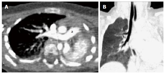
Axial (A) and coronal MinIP (B) images show absent left lung with left sided mediastinal shift and volume loss. Main pulmonary artery (a) continues as right pulmonary artery with absent left pulmonary artery. There is also associated absence of left main bronchus. MinIP: Minimum intensity projection.
- Citation: Jugpal TS, Garg A, Sethi GR, Daga MK, Kumar J. Multi-detector computed tomography imaging of large airway pathology: A pictorial review. World J Radiol 2015; 7(12): 459-474
- URL: https://www.wjgnet.com/1949-8470/full/v7/i12/459.htm
- DOI: https://dx.doi.org/10.4329/wjr.v7.i12.459


