Copyright
©2012 Baishideng Publishing Group Co.
World J Radiol. Jun 28, 2012; 4(6): 273-277
Published online Jun 28, 2012. doi: 10.4329/wjr.v4.i6.273
Published online Jun 28, 2012. doi: 10.4329/wjr.v4.i6.273
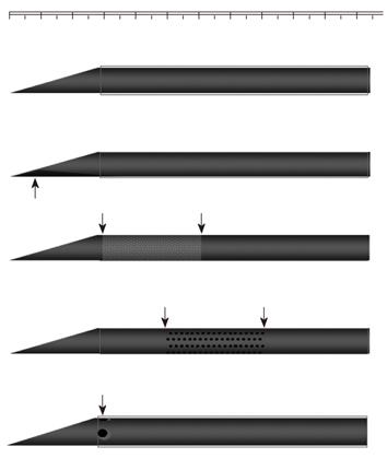
Figure 1 Schematic drawings of a commercially available puncture needle and four newly devised vascular puncture needles (18 gauge).
Top to bottom: re-cut needle, dimple needle, rough-surface needle (rough over the section of needle located 3-6 mm from the tip), and needle with four side holes.
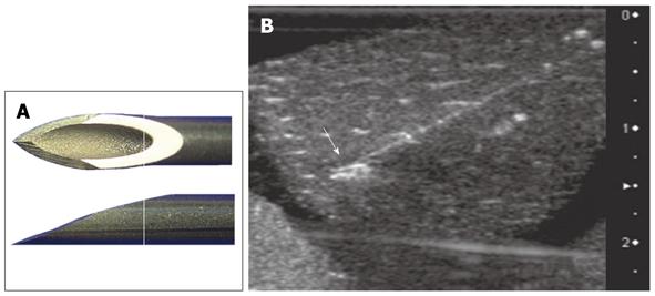
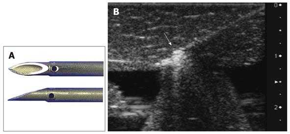
Figure 2 Commercially available vascular needle (control).
A: Needle tip; B: Corresponding ultrasound image. The arrow indicates the needle tip.
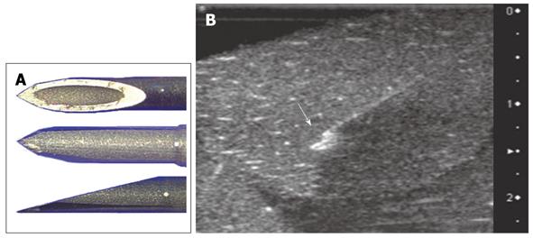
Figure 3 Vascular needle with re-cutting of the dorsal aspect of the tip.
A: Needle tip; B: Corresponding ultrasound image. The arrow indicates the needle tip.
Figure 4 Vascular needle with a rough-filed surface at 3-6 mm from the tip of the needle.
A: Needle tip, shaft; B: Corresponding ultrasound image, with the rough surface indicated by the arrow.
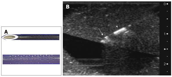
Figure 5 Vascular needle with dimples placed at 5-8 mm from the tip (dimple needle).
A: Needle tip, shaft; B: Corresponding ultrasound image, with the dimples indicated by the arrowhead and the needle tip indicated by the arrow.
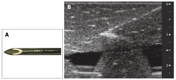
Figure 6 Vascular needle with four side holes, each 0.
4 mm in diameter, drilled at 4 mm from the tip of the needle. A: Needle tip, shaft. The side holes are covered by the outer sheath. B: Corresponding ultrasound image. The arrow indicates the needle tip with side holes.
-
Citation: Kawai N, Minamiguchi H, Sato M, Nakai M, Sanda H, Tanaka T, Ikoma A, Nakata K, Shirai S, Sonomura T. Evaluation of vascular puncture needles with specific modifications for enhanced ultrasound visibility:
In vitro study. World J Radiol 2012; 4(6): 273-277 - URL: https://www.wjgnet.com/1949-8470/full/v4/i6/273.htm
- DOI: https://dx.doi.org/10.4329/wjr.v4.i6.273


