Copyright
©2010 Baishideng Publishing Group Co.
World J Radiol. Nov 28, 2010; 2(11): 434-439
Published online Nov 28, 2010. doi: 10.4329/wjr.v2.i11.434
Published online Nov 28, 2010. doi: 10.4329/wjr.v2.i11.434
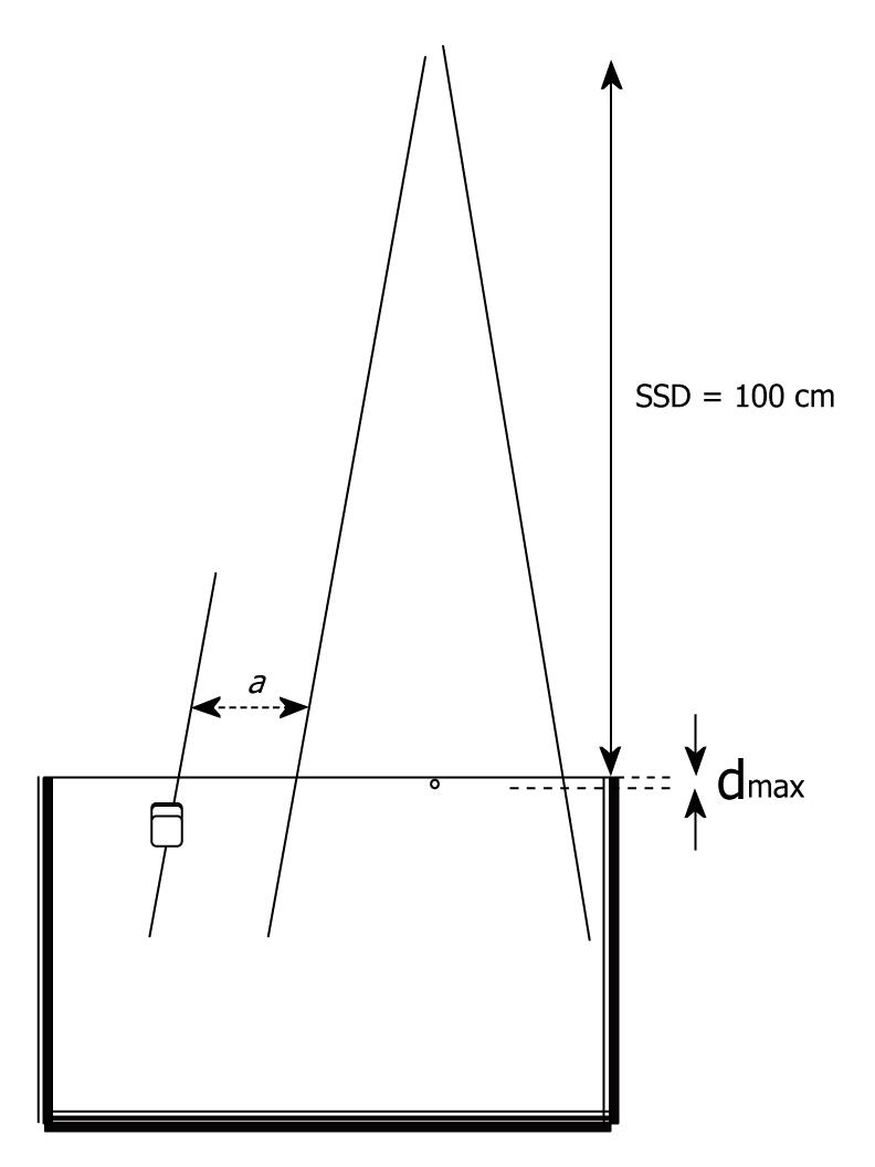
Figure 1 Geometry set-up of the peripheral dose measurements in a water phantom where a is the distance from the edge of the field (from 1 to 18 cm) where the MOSFET dosimeter was placed, and dmax is 1.
5 and 3.3 cm for 6 and 18 MV, respectively. This shape represents the MOSFET dosimeter.
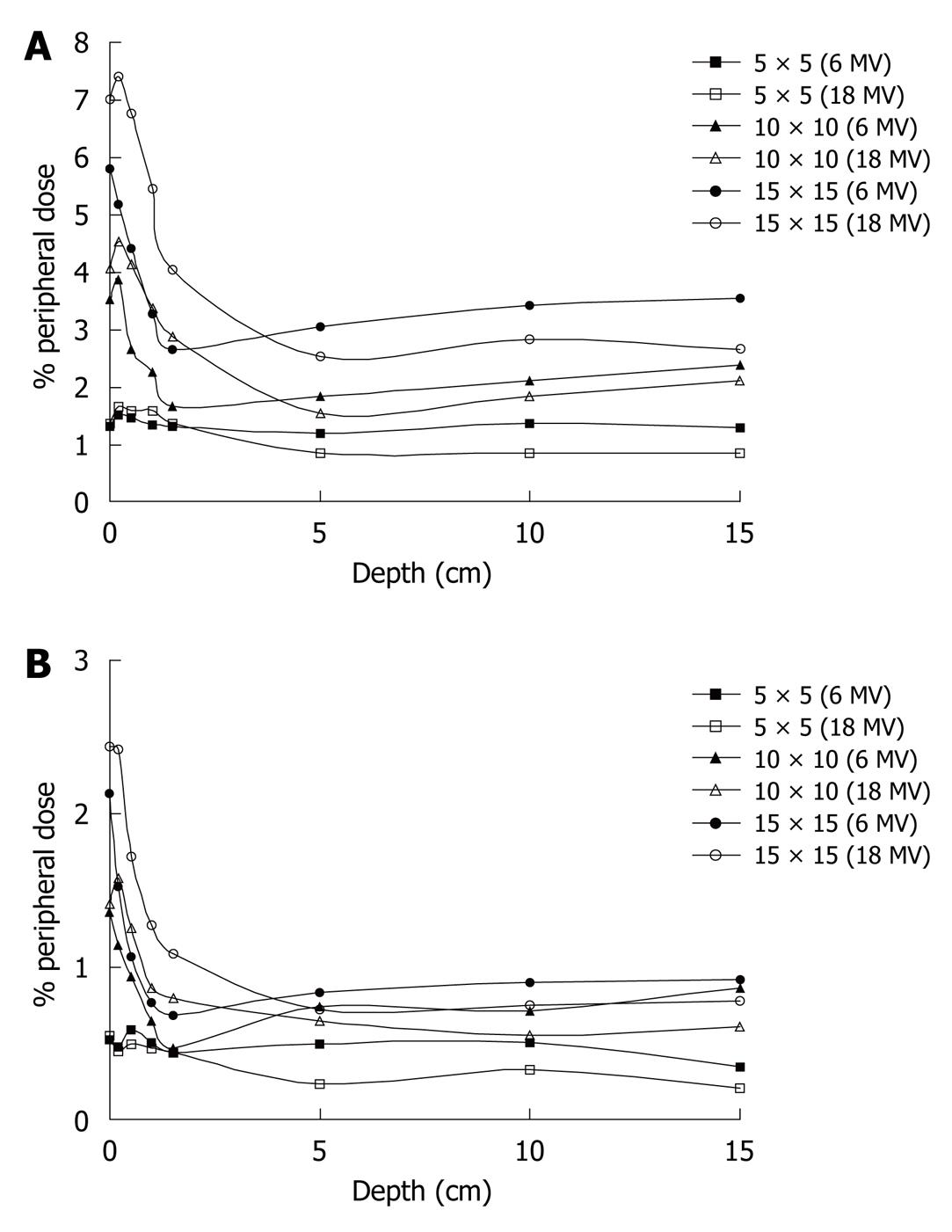
Figure 2 Effect of depth on percentage peripheral dose for 6 and 18 MV beams for various field sizes at (A) 5 cm off axis distance and (B) 15 cm off axis distance.
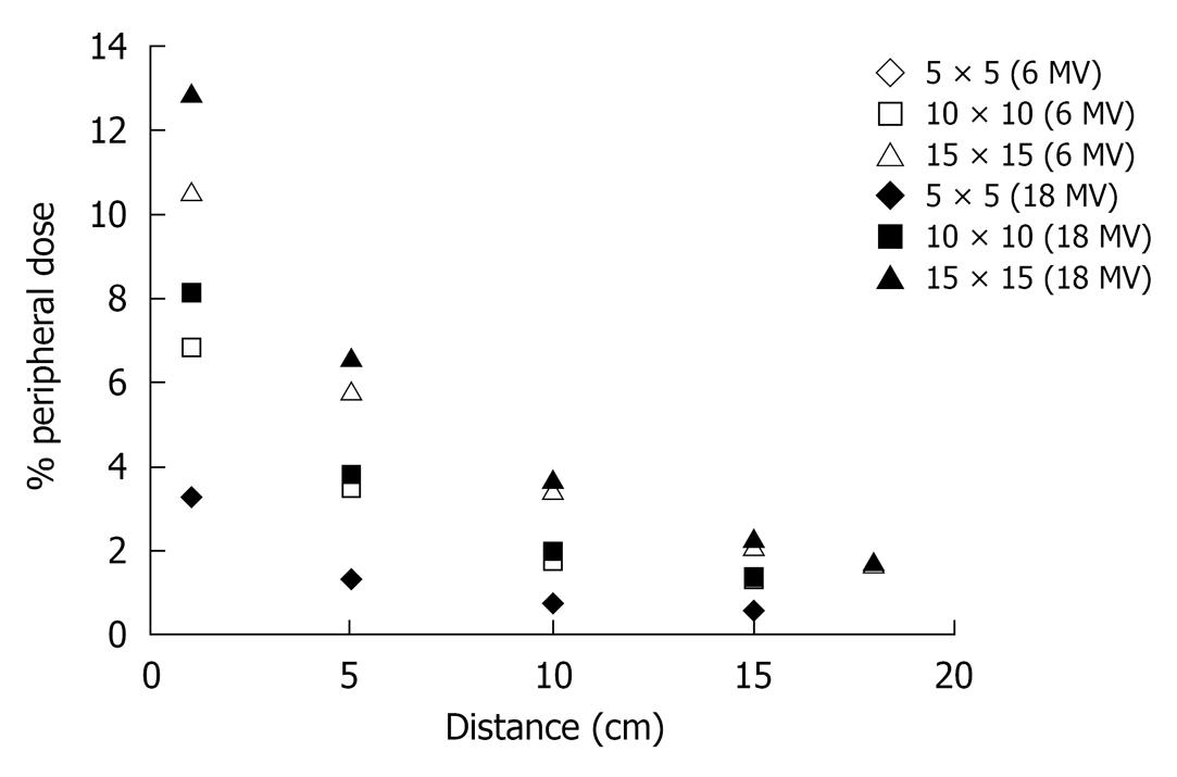
Figure 3 Percentage peripheral dose at surface vs distance from the field edge for various field sizes and both energies.
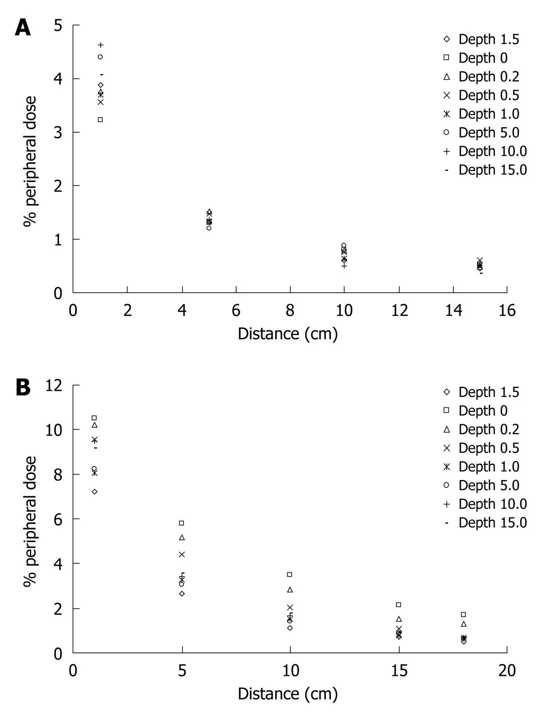
Figure 4 Effect of distance on percentage peripheral dose, using the 6 MV beam, for various depths for (A) 5 cm × 5 cm and (B) 15 cm × 15 cm.
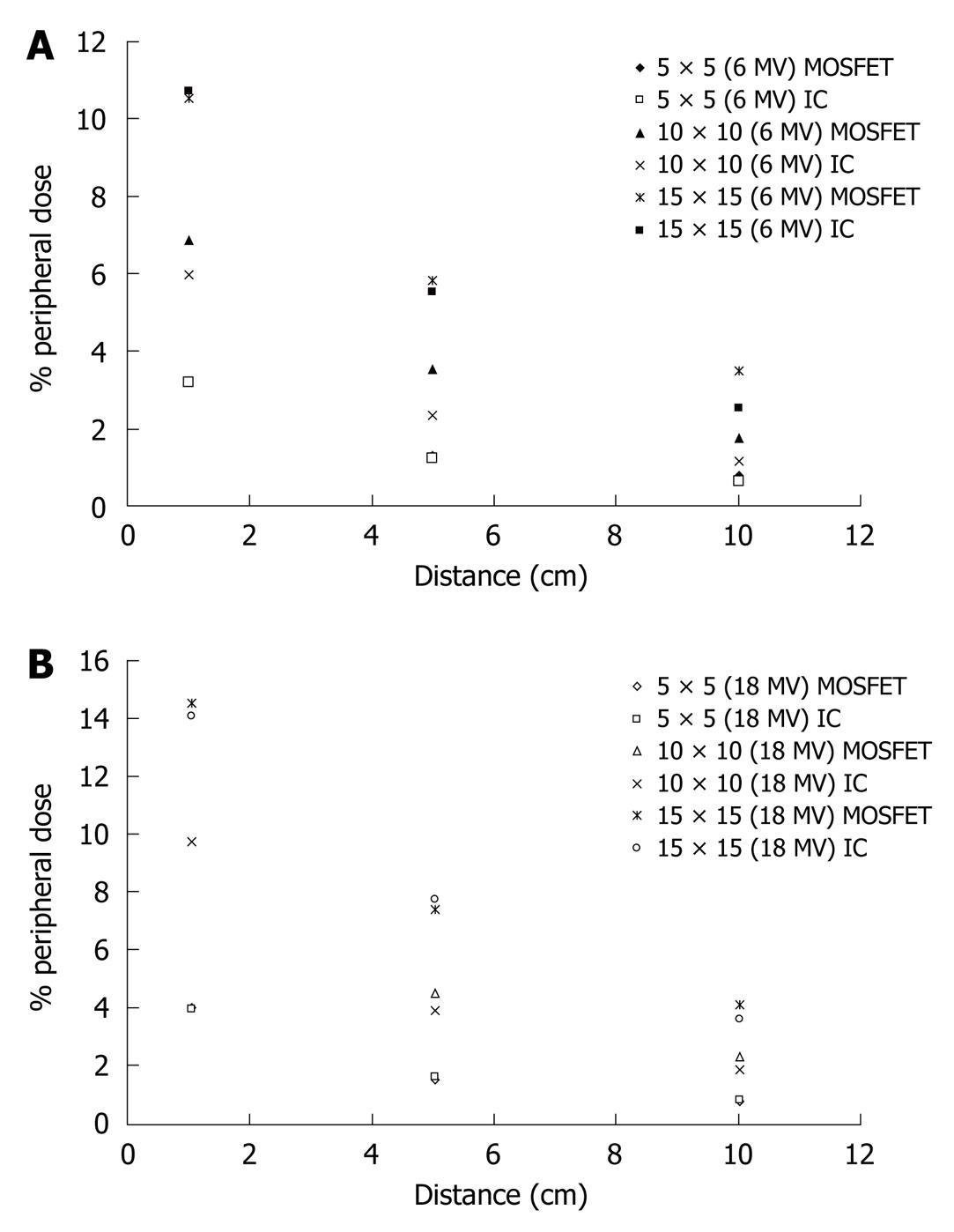
Figure 5 Percentage peripheral dose obtained with metal oxide semiconductor field effect transistor and the ionization chamber for various field sizes as a function of distance from the surface using the (A) 6 MV and (B) 18 MV beam.
MOSFET: Metal oxide semiconductor field effect transistor.
Figure 6 Coefficient of variation vs dose.
- Citation: Vlachopoulou V, Malatara G, Delis H, Theodorou K, Kardamakis D, Panayiotakis G. Peripheral dose measurement in high-energy photon radiotherapy with the implementation of MOSFET. World J Radiol 2010; 2(11): 434-439
- URL: https://www.wjgnet.com/1949-8470/full/v2/i11/434.htm
- DOI: https://dx.doi.org/10.4329/wjr.v2.i11.434


