Copyright
©The Author(s) 2017.
World J Cardiol. Apr 26, 2017; 9(4): 384-390
Published online Apr 26, 2017. doi: 10.4330/wjc.v9.i4.384
Published online Apr 26, 2017. doi: 10.4330/wjc.v9.i4.384
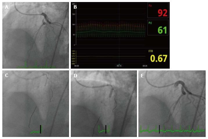
Figure 1 Angiographic findings for case 1.
A: Diagnostic angiogram; B: Fractional flow reserve of left anterior descending artery; C: Stent positioning using Szabo technique; D: Inflation of stent balloon; E: Final angiogram after stent deployment.
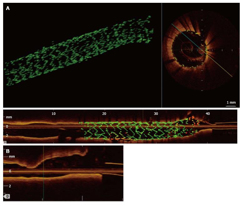
Figure 2 Optical coherence tomography images for case 1.
A: Three-dimensional reconstruction of OCT; B: Cross-sectional OCT image through stent (top right); two-dimensional view of LAD that shows the proximal stent terminating just at the bifurcation with part of one stent strut protruding into the bifurcation; C: OCT of high diagonal does not show protrusion of stent struts into the main vessel; OCT: Optical coherence tomography; LAD: Left anterior descending.
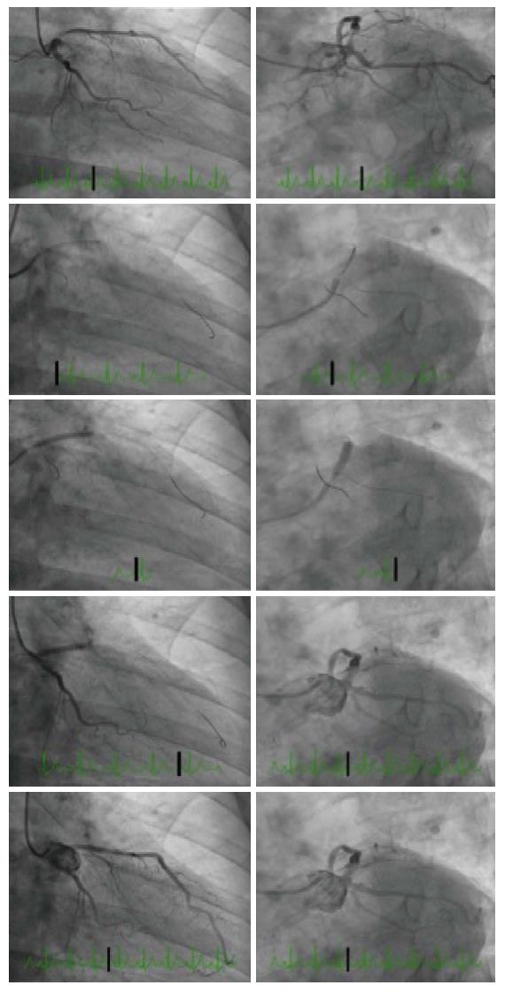
Figure 3 Angiographic images for case 2.
Coronary angiography showed separate ostia of the LAD and left circumflex artery (LCx) and proximal moderate to severe LAD stenosis. RAO caudal (left) and LAO caudal (right) images with diagnostic images (top), Szabo technique (center three panels) and final images (bottom). LAD: Left anterior descending; LCx: Left circumflex artery.
Figure 4 Optical coherence tomography images for case 2.
A: Three-dimensional OCT of LAD shows excellent stent apposition; B: OCT of left circumflex does not show protrusion of stent struts. LAD: Left anterior descending; OCT: Optical coherence tomography.
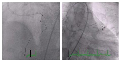
Figure 5 Angiographic images illustrate the position of the stent and the side branch anchor during this technique.
- Citation: Yu K, Hundal H, Zynda T, Seto A. Three-dimensional optical coherence tomography reconstruction of bifurcation stenting using the Szabo anchor-wire technique. World J Cardiol 2017; 9(4): 384-390
- URL: https://www.wjgnet.com/1949-8462/full/v9/i4/384.htm
- DOI: https://dx.doi.org/10.4330/wjc.v9.i4.384


