Copyright
©The Author(s) 2015.
World J Cardiol. Jul 26, 2015; 7(7): 415-422
Published online Jul 26, 2015. doi: 10.4330/wjc.v7.i7.415
Published online Jul 26, 2015. doi: 10.4330/wjc.v7.i7.415
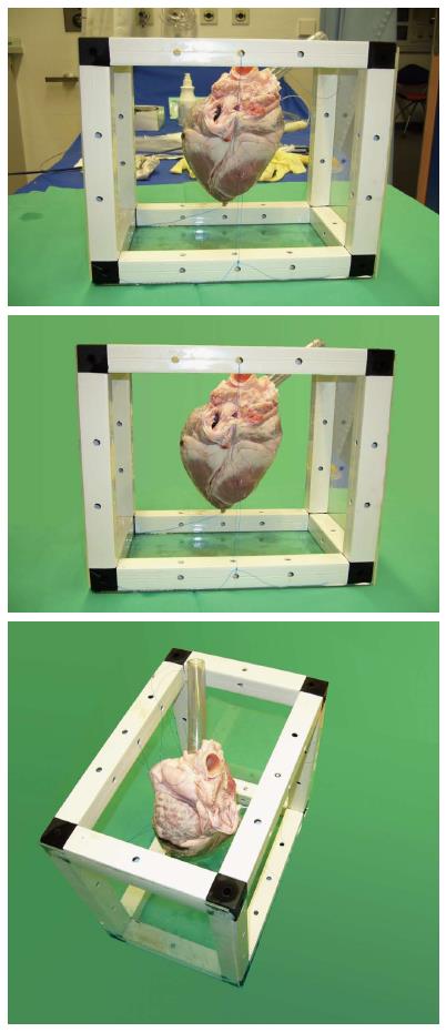
Figure 1 Model of swine heart with plastic tube attached to the trunk of the vena cava.
The heart is fixated in a plastic frame to maintain form and position when submerged into the saline filled phantom.
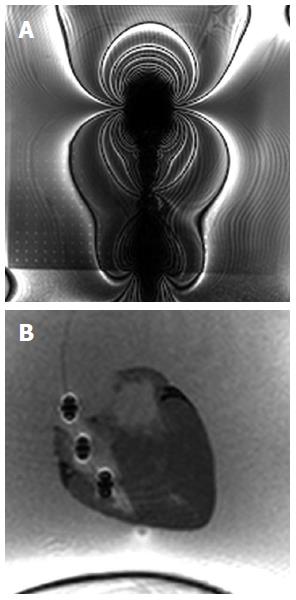
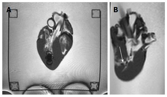
Figure 2 Cardiac magnetic resonance imaging-Images of conventional bioptome for endomyocardial applications (A), novel bioptome with three metal markers at the distal end inserted into a swine heart model (B).
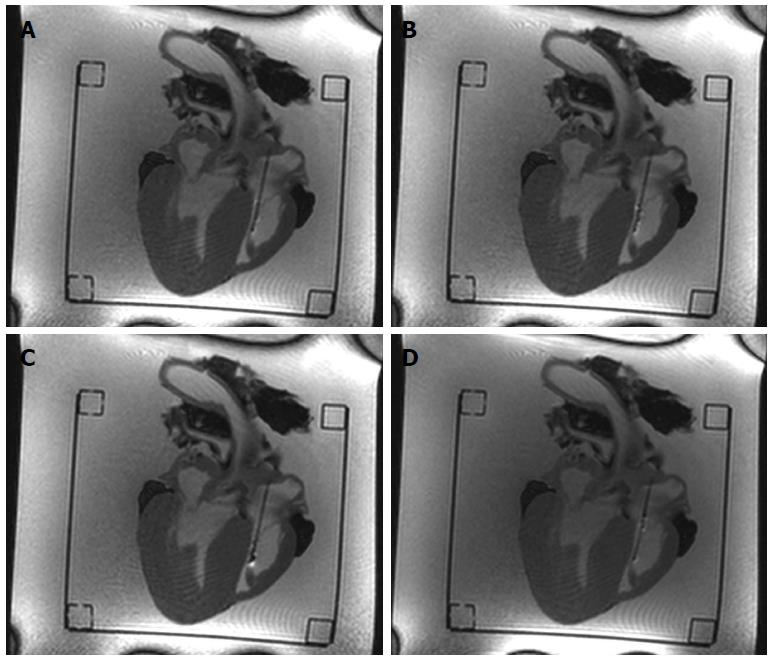
Figure 3 Real-time magnetic resonance image frames showing bioptome inside bovine heart.
The bioptome is pushed forward through a plastic tube (A, B), is bare in the heart model (C) and then pulled back (D).
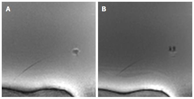
Figure 4 Real-time magnetic resonance imaging image frames with closed (A) and opened (B) cutter.
Figure 5 Real-time magnetic resonance imaging image frames with opened (A) and moving (B) tip.
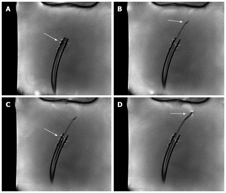
Figure 6 Real-time magnetic resonance imaging image frames showing bioptome and sheath inside saline filled phantom.
The empty sheath is pushed forward in a plastic tube (A, B), later the bioptome is guided inside the sheath (C) until the tip is bare in the phantom (D).
Figure 7 Close-up images of experimental in-vitro setup as shown in Figure 1: Opened porcine heart model with magnetic resonance bioptome (white) advanced through sheath (blue) (A), opened magnetic resonance bioptome forceps (B), magnetic resonance bioptome with tissue sample retrieved from endocardium (C).
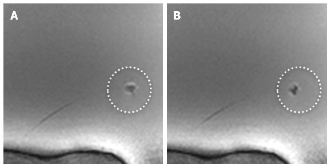
Figure 8 Side by side comparison of initial (A) and improved (B) version of magnetic resonance imaging compatible bioptome.
Note the huge artifact in (A). The tip is highlighted in the circle. The targeted region is marked by previous Gadolinium injection (arrow).
-
Citation: Lossnitzer D, Seitz SA, Krautz B, Schnackenburg B, André F, Korosoglou G, Katus HA, Steen H. Feasibility of real-time magnetic resonance imaging-guided endomyocardial biopsies: An
in-vitro study. World J Cardiol 2015; 7(7): 415-422 - URL: https://www.wjgnet.com/1949-8462/full/v7/i7/415.htm
- DOI: https://dx.doi.org/10.4330/wjc.v7.i7.415


