Copyright
©The Author(s) 2022.
World J Cardiol. Mar 26, 2022; 14(3): 108-138
Published online Mar 26, 2022. doi: 10.4330/wjc.v14.i3.108
Published online Mar 26, 2022. doi: 10.4330/wjc.v14.i3.108
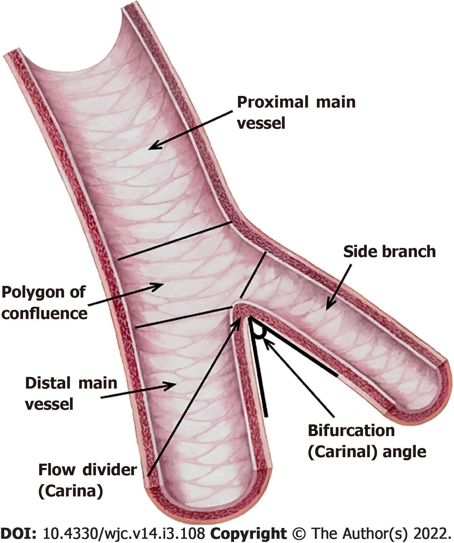
Figure 1 Coronary bifurcation anatomy.
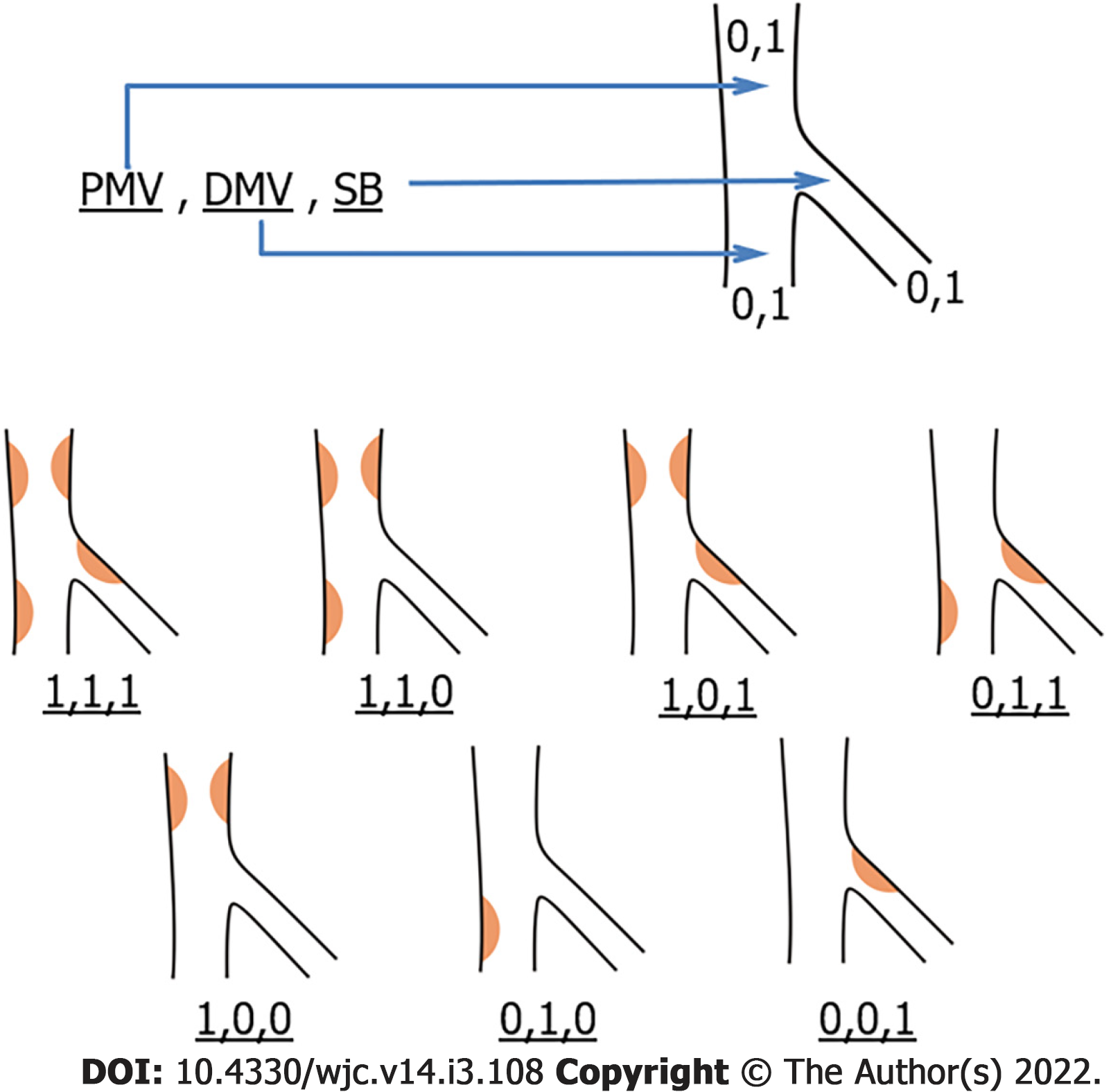
Figure 2 Medina classification.
“1” indicates ≥ 50% stenosis, and “0” indicates < 50% stenosis. Atherosclerosis is most often seen in the lateral walls of vessels where endothelial shear stress is low and oscillatory. DMV: Distal main vessel; PMV: Proximal main vessel; SB: Side branch.
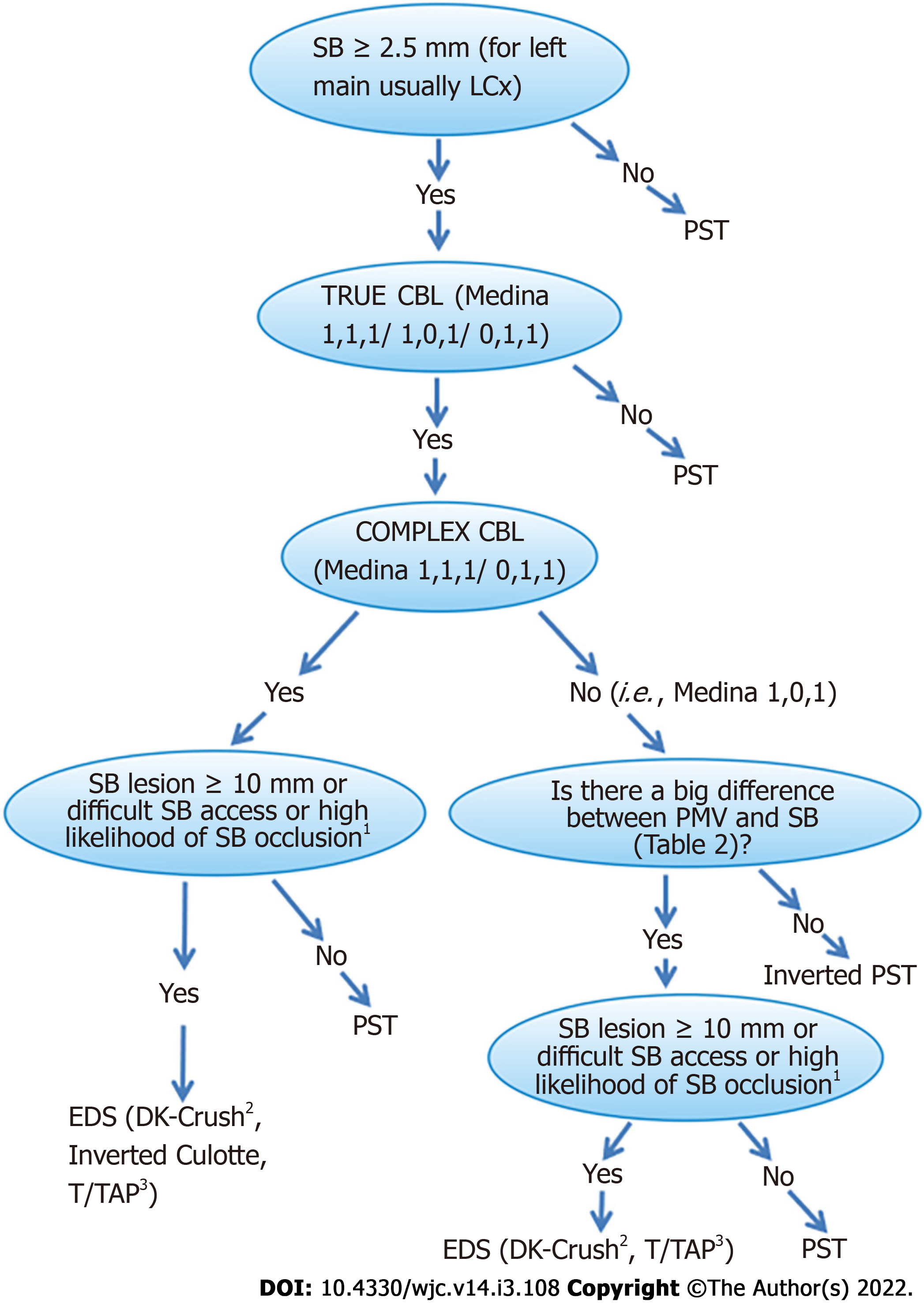
Figure 3 Proposed algorithm for selecting an optimum percutaneous coronary intervention strategy in both left main coronary artery and non-left main coronary artery bifurcation lesions.
1Plaque on the same side of SB, SB stenosis > 50%, POC stenosis > 50%, bifurcation angle > 70%, MV/SB diameter ratio (diameter of PMV+DMV/2×diameter of SB) >1 and low MV TIMI flow grade are predictors of a high likelihood of SB occlusion. The larger the size of the numbers and/or the lower the TIMI flow grade and/or the more predictors, the higher the risk of SB occlusion. A recently created SB occlusion risk score may be used[44]. 2The DK-crush technique seems to be preferable to the other EDS techniques in view of the recent data; however, the operator’s experience is decisive in the choice between the EDS technique and is important in obtaining the best result. 3The TAP technique cannot be considered the upfront technique in cases with difficult SB access and a high risk of SB occlusion because of SB stenting after MV stenting. CBL: Coronary bifurcation lesion; EDS: Elective double stenting; LCx: Left circumflex artery; LMCA: Left main coronary artery; MV: Main vessel; POC: Polygon of confluence; PST: Provisional stenting technique; SB: Side branch.
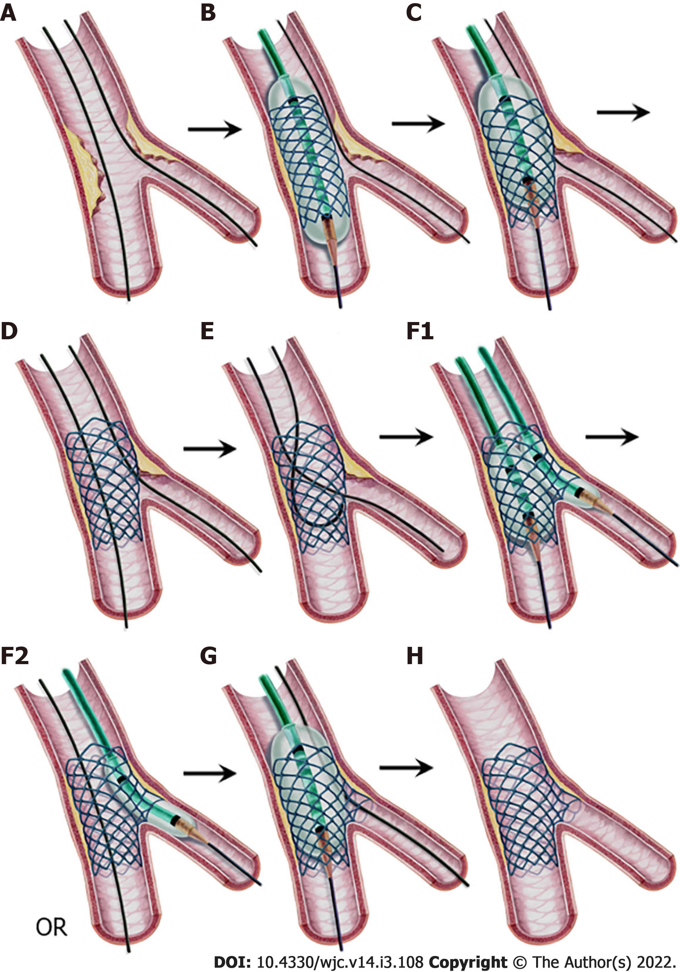
Figure 4 Provisional stenting technique, step-by-step.
A: Both branches are wired; B: A stent sized to the distal MV diameter is implanted in the MV; C: Proximal optimization technique (POT) application with a balloon sized to the proximal MV diameter with its distal shoulder aligned to the carina; D: Stent view after POT. If the result is satisfactory, stop here. If not, proceed to step E; E: Guidewire exchange; First, the SB is wired through the most distal cell. Second, the retracted and released SB wire is advanced into the distal MV as a “U” shape; F1: Kissing balloon inflation sized to branch diameters, or F2: SB ostium ballooning as a part of the POT-side-POT technique; G: Final POT; and H: Final result. MV: Main vessel; POT: Proximal optimization technique; SB: Side branch.
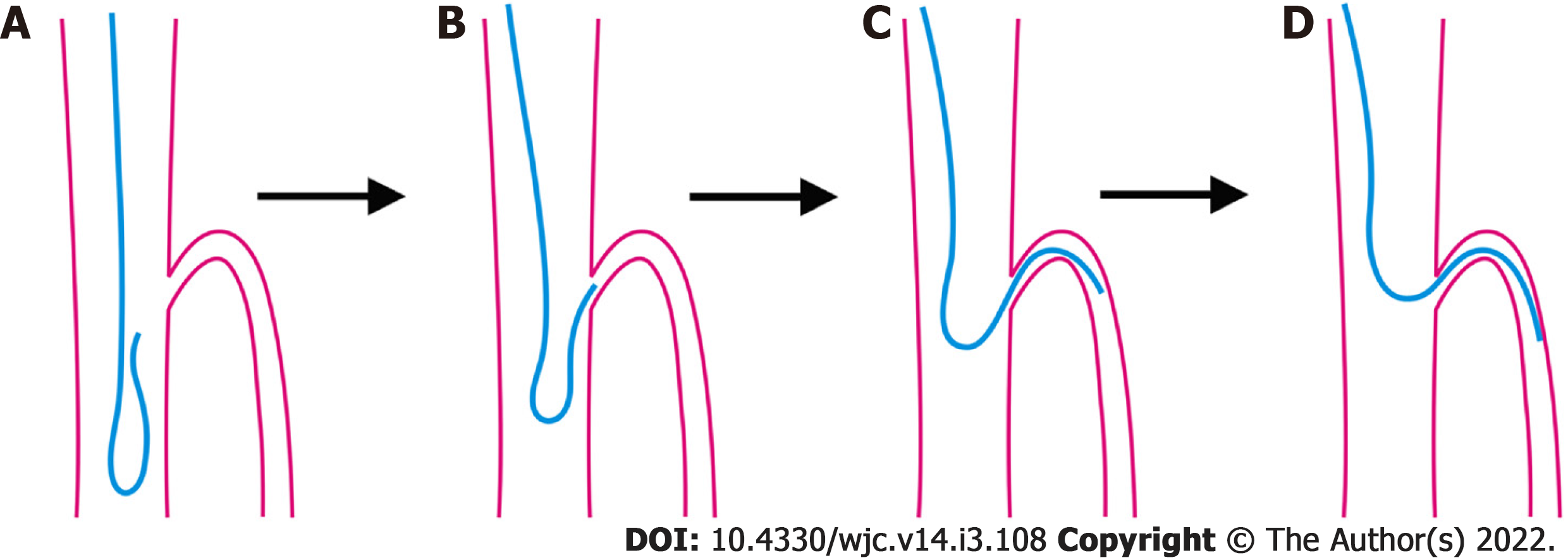
Figure 5 Reverse wire technique.
A, B: The wire shaped as a hairpin is advanced into the distal main vessel and withdrawn back to the carina; C, D: When the tip intubates the side branch (SB) ostium, slight withdrawal and gentle counterclockwise rotation allow the wire to advance in the SB.
Figure 6 Jailed balloon technique and jailed semi-inflated balloon technique.
A: A balloon is positioned in the side branch (SB) to align or 1-2 mm proximal to the main vessel (MV) stent in the proximal MV; B: The stent is deployed while the SB balloon is kept inflated at a low or moderate pressure (in the jailed semi-inflated balloon technique) or uninflated (in the jailed balloon technique); C: Both balloons are removed; D: Proximal optimization technique sized to the proximal MV diameter; and E: Final result.
Figure 7 Modified jailed balloon technique.
A: Semicompliant balloon in the side branch is positioned with its proximal end touching the main vessel (MV) stent; B: Both the MV stent and balloon are inflated at the same nominal pressure; C: Both balloons are removed; D: Proximal optimization technique sized to proximal MV diameter; E: Final result.
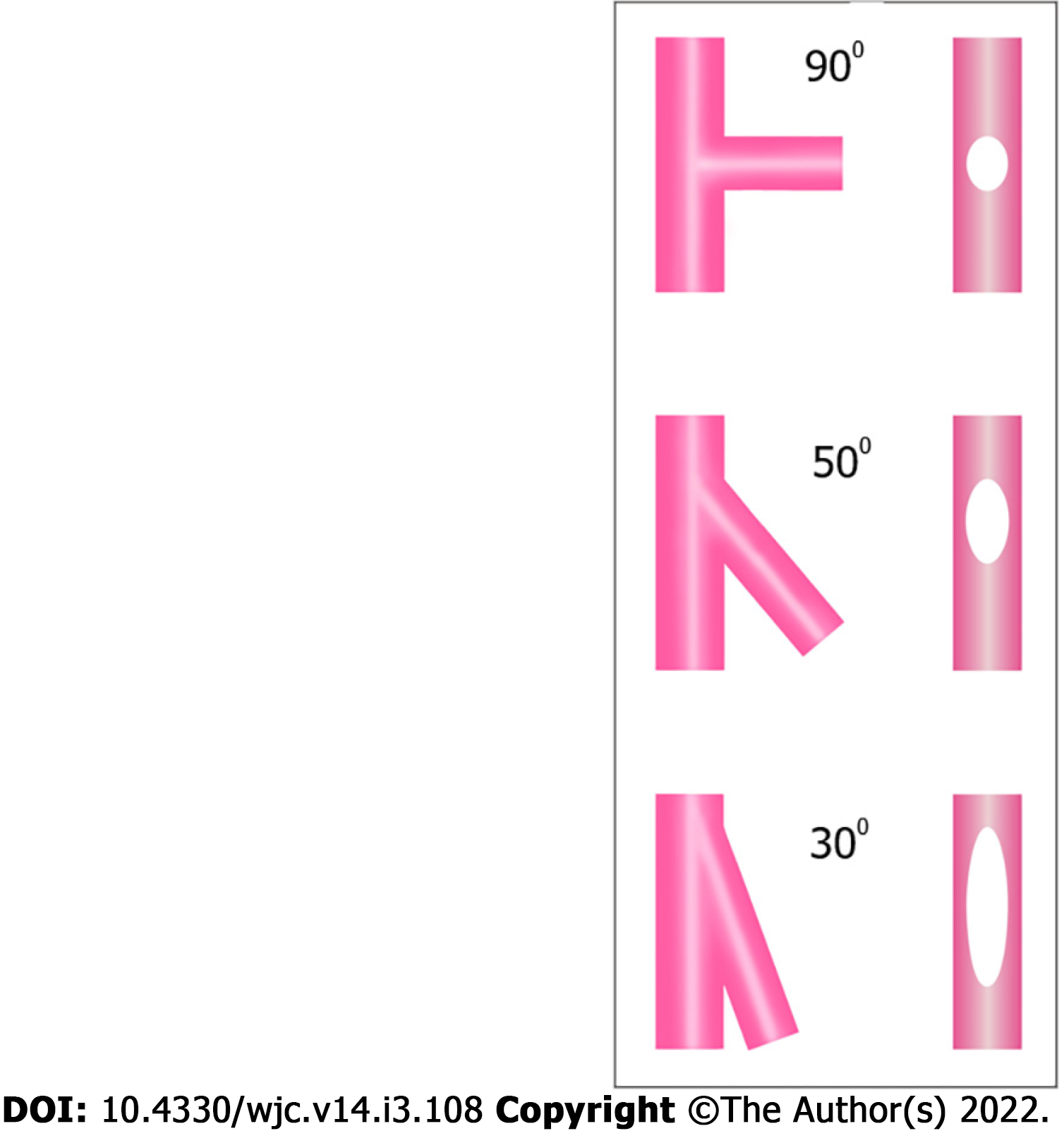
Figure 8 Effect of bifurcation angle on side branch ostium ellipticity.
Narrower angles result in more oval ostium shapes.
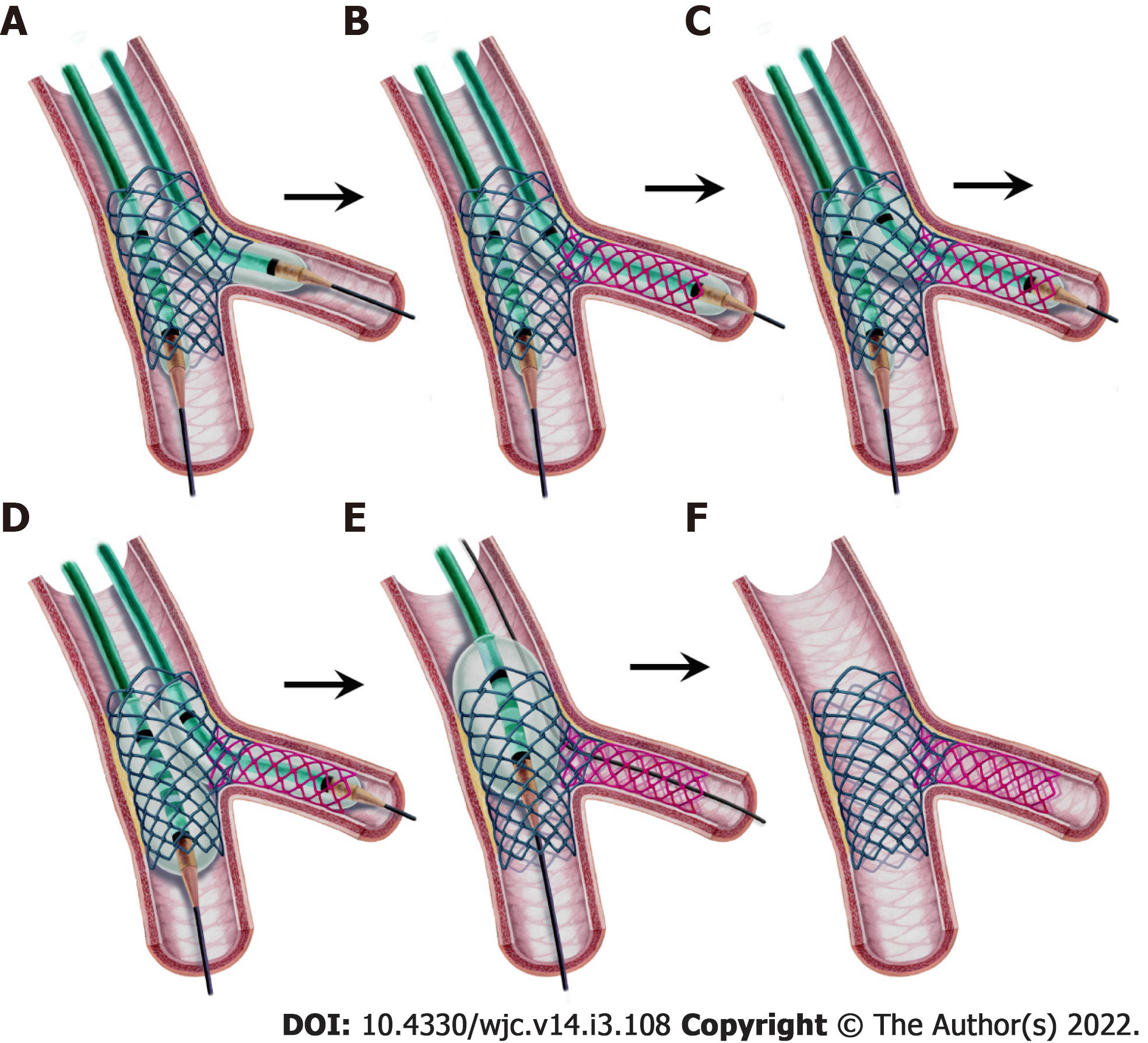
Figure 9 Step-by-step T and protrusion technique.
A: After main vessel (MV) stenting, an uninflated balloon is positioned in the MV, and the side branch (SB) ostium is dilated by a balloon; B: The SB stent is deployed with minimal protrusion and covers the ostium completely; C: The stent balloon is withdrawn slightly and inflated at high pressure; D: Kissing balloon inflation; E: Proximal optimization technique with a short balloon not reaching the neocarina. (This step is not mandatory if the kissing balloon inflation area in the proximal MV is not long.); F: Final result.
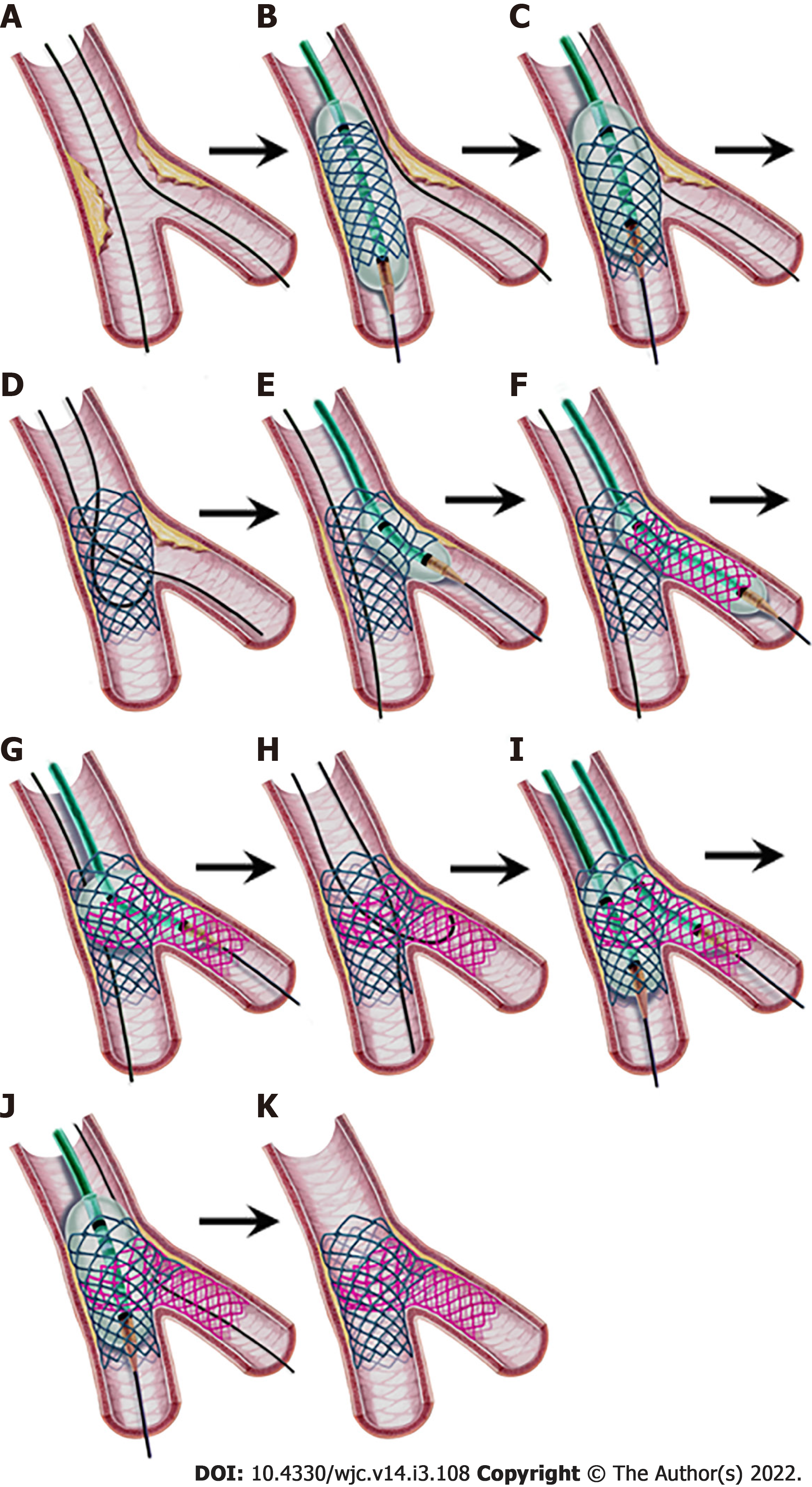
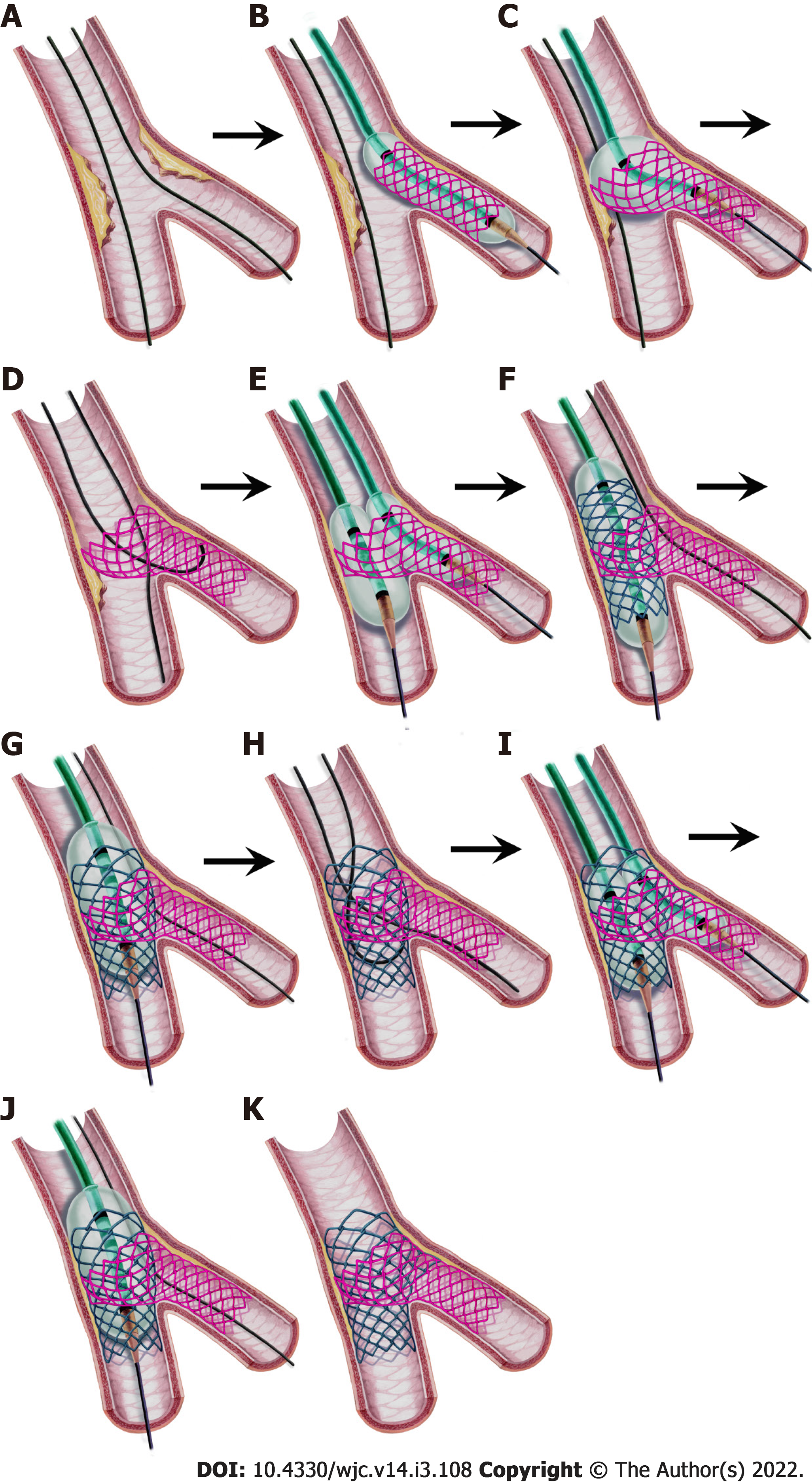
Figure 10 Step-by-step classical (provisional) culotte stenting.
A: Both vessels are wired; B: After predilatation, the main vessel (MV) stent sized to the distal MV is deployed; C: First proximal optimization technique (POT); D: Wire exchange; E: Balloon dilatation of the side branch (SB) ostium; F: Deployment of the SB stent protruding into the proximal MV (1-3 mm in “mini-culotte”(shown) or more in classical culotte technique); G: POT for the SB stent; H: Second wire exchange with wiring the distal MV through the closest cell to the carina, and the other wire tip is “U” shaped to cross the SB stent; I: Kissing balloon inflation; J: Final POT; K: Final result.
Figure 11 Step-by-step inverted culotte stenting.
A: Both vessels are wired; B: The side branch (SB) stent protruding in the proximal main vessel is deployed (protrusion part is 1-3 mm in the “Mini-culotte technique”); C: Proximal optimization technique (POT) for the SB stent; D: Wire exchange. The distal main vessel (MV) wiring from the closest cell to the carina and the “U” shaped wire is advanced into the SB; E: Kissing balloon inflation (KBI) (in the “double kissing mini-culotte “technique) or classical balloon dilatation only in the distal MV ostium may be performed; F: MV stenting; G: POT for the MV stent; H: Second wire exchange. Wiring the SB through the closest cell to the carina and the “U” shaped wire crossing the MV stent; I: KBI; J: Final POT; K: Final result.
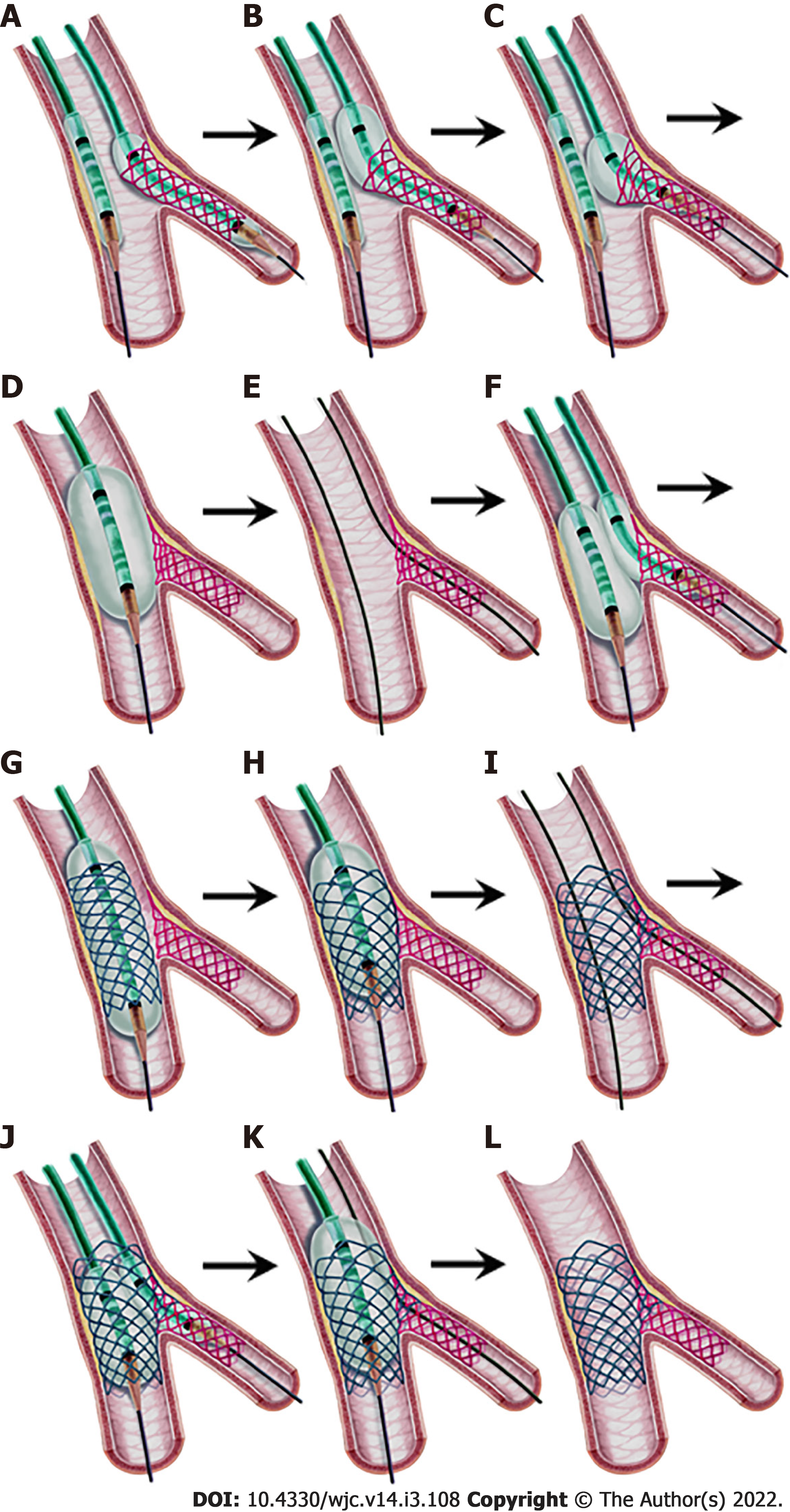
Figure 12 Step-by-step double kissing-crush technique.
A: After the preparation of the vessels, the side branch (SB) stent protruding 2-3 mm into the proximal main vessel (MV) is deployed while an uninflated proximal optimization technique (POT) balloon is positioned in the MV; B, C: “Proximal side optimization”. A slightly withdrawn stent balloon is inflated at a higher pressure. Then, a new larger NC balloon is inflated in the protruding stent part to further open the struts; D: Crushing the stent by POT after the SB balloon and wire are removed; E: Wiring the SB through a non-distal cell; F: First kissing balloon inflation (KBI) after sequential inflation of the two balloons; G: MV stenting after the SB balloon and wire are removed; H: Second POT; I: Wiring the SB through a non-distal cell for the second time; J: Second KBI; K: Final POT; L: Final result.
- Citation: Kırat T. Fundamentals of percutaneous coronary bifurcation interventions. World J Cardiol 2022; 14(3): 108-138
- URL: https://www.wjgnet.com/1949-8462/full/v14/i3/108.htm
- DOI: https://dx.doi.org/10.4330/wjc.v14.i3.108


