Copyright
©The Author(s) 2018.
World J Cardiol. Oct 26, 2018; 10(10): 153-164
Published online Oct 26, 2018. doi: 10.4330/wjc.v10.i10.153
Published online Oct 26, 2018. doi: 10.4330/wjc.v10.i10.153
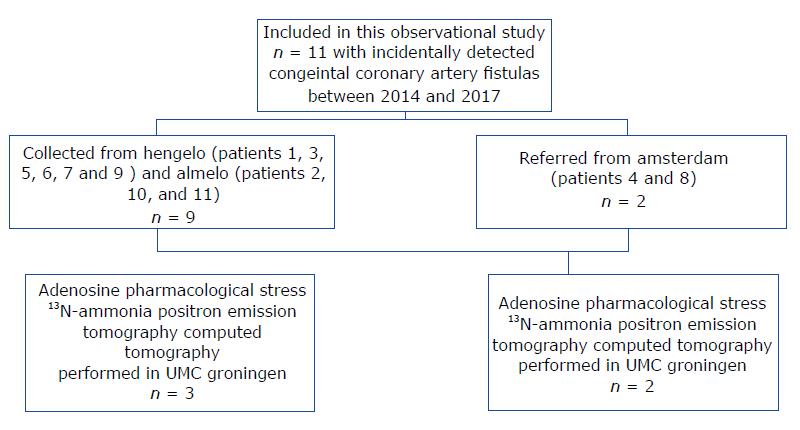
Figure 1 Flowchart of the study patients who were collected from 3 different non-academic Dutch institutes.
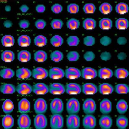
Figure 2 99mTc-sestamibi single-photon emission computed tomography scintigraphy, demonstrating normal myocardial perfusion and a normal left ventricular ejection fraction.
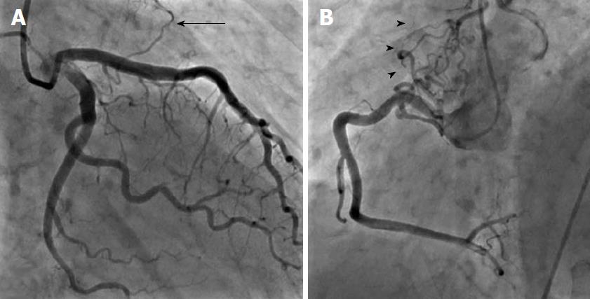
Figure 3 Bilateral fistulas.
A: Balateral fistulas from the left anterior descending coronary artery to the pulmonary artery with single origin, multiple pathway and single termination (arrow); B: Balateral fistulas from the right coronary artery to the PA with multiple origin, pathway and termination (arrowheads).
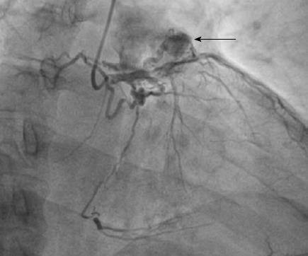
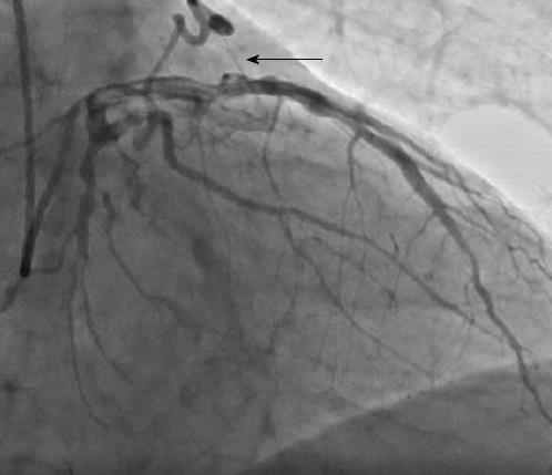
Figure 4 Fistula from the proximal left anterior descending coronary artery to pulmonary artery with multiple origin, pathway and termination associated with large aneurysmal formation (arrow).
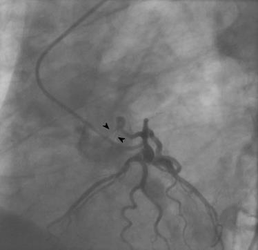
Figure 5 Fistula from the proximal left circumflex artery ending into the pulmonary artery characterized with single origin, pathway and termination emptying with double jets (arrowheads) ending into the pulmonary artery.
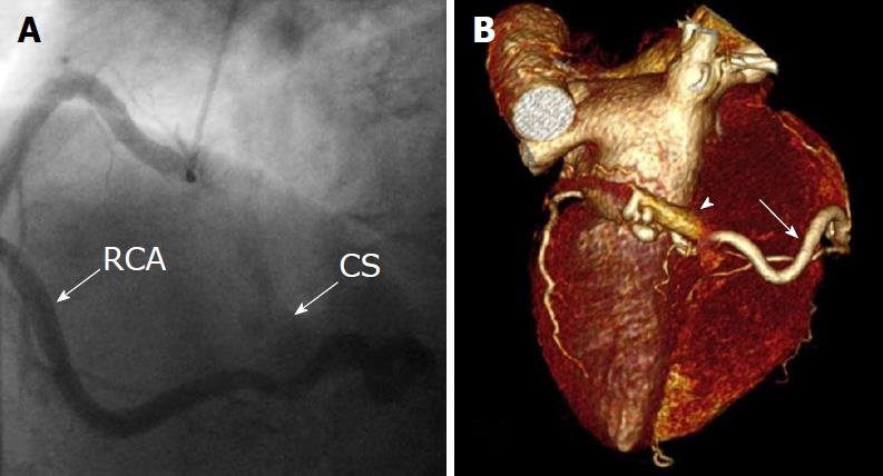
Figure 6 Unilateral fistula and computed tomography coronary angiography.
A: Unilateral fistula originating from the right coronary artery (RCA) terminating into the coronary sinus (CS) with single origin, pathway and termination with dilated RCA and enlarged CS; B: Computed tomography coronary angiography: Coronary artery fistula originating from the distal segment of RCA (arrow) and terminating into the coronary sinus. Volume-rendered three-dimensional image reconstruction demonstrating fistulous vessel located posterior connected with the CS (arrowhead). RAC: Right coronary artery; CS: Coronary sinus.
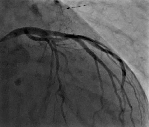
Figure 7 A fistulous connection between the left anterior descending coronary artery and pulmonary artery with single origin, pathway and termination with a single jet ending into the pulmonary artery (arrow).
Figure 8 Right anterior oblique view shows the fistulous vessel between the left anterior descending coronary artery and the pulmonary artery with multiple origin, pathway and termination with small aneurysmal formation (arrow).
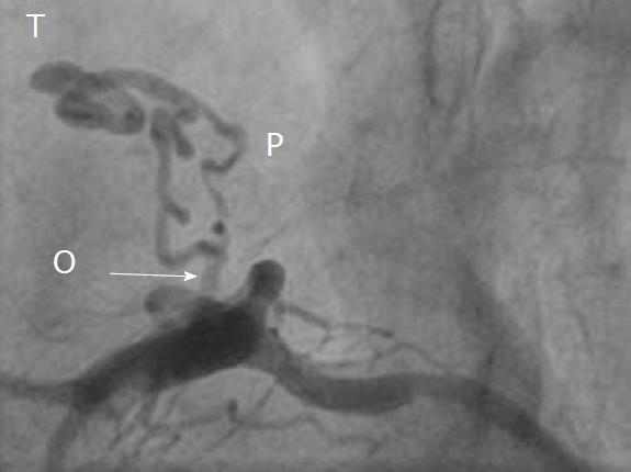
Figure 9 Left lateral frame demonstrating a fistula with multiple origin (arrow) and pathway from the proximal left anterior descending coronary artery ending to the pulmonary artery with a single termination.
O: Origin; P: Pathway; T: Termination.
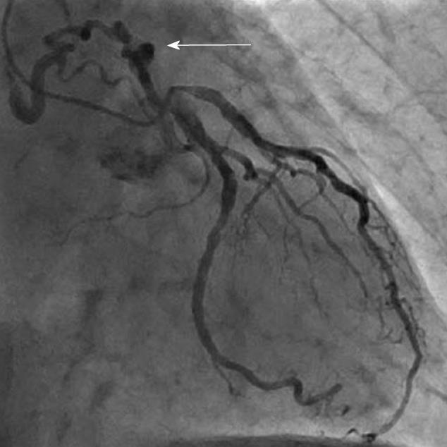
Figure 10 Left anterior oblique view shows a fistula between proximal left circumflex coronary artery (arrow) with multiple origin, pathway and termination with outflow to the pulmonary artery.
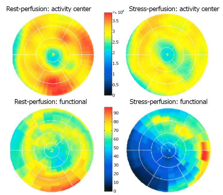
Figure 11 Positron emission tomography computed tomography scanning demonstrating normal findings on the rest 13N-ammonia polar map (left panel) and normal perfusion on adenosine 13N-ammonia polar map (right panel).
Myocardial perfusion was assessed at rest and during vasodilator pharmacological stress induced by adenosine, using 400 MBq of 13N-ammonia as the perfusion radiotracer.
- Citation: Said SA, Agool A, Moons AH, Basalus MW, Wagenaar NR, Nijhuis RL, Schroeder-Tanka JM, Slart RH. Incidental congenital coronary artery vascular fistulas in adults: Evaluation with adenosine-13N-ammonia PET-CT. World J Cardiol 2018; 10(10): 153-164
- URL: https://www.wjgnet.com/1949-8462/full/v10/i10/153.htm
- DOI: https://dx.doi.org/10.4330/wjc.v10.i10.153


