Copyright
©The Author(s) 2024.
World J Gastrointest Surg. May 27, 2024; 16(5): 1385-1394
Published online May 27, 2024. doi: 10.4240/wjgs.v16.i5.1385
Published online May 27, 2024. doi: 10.4240/wjgs.v16.i5.1385
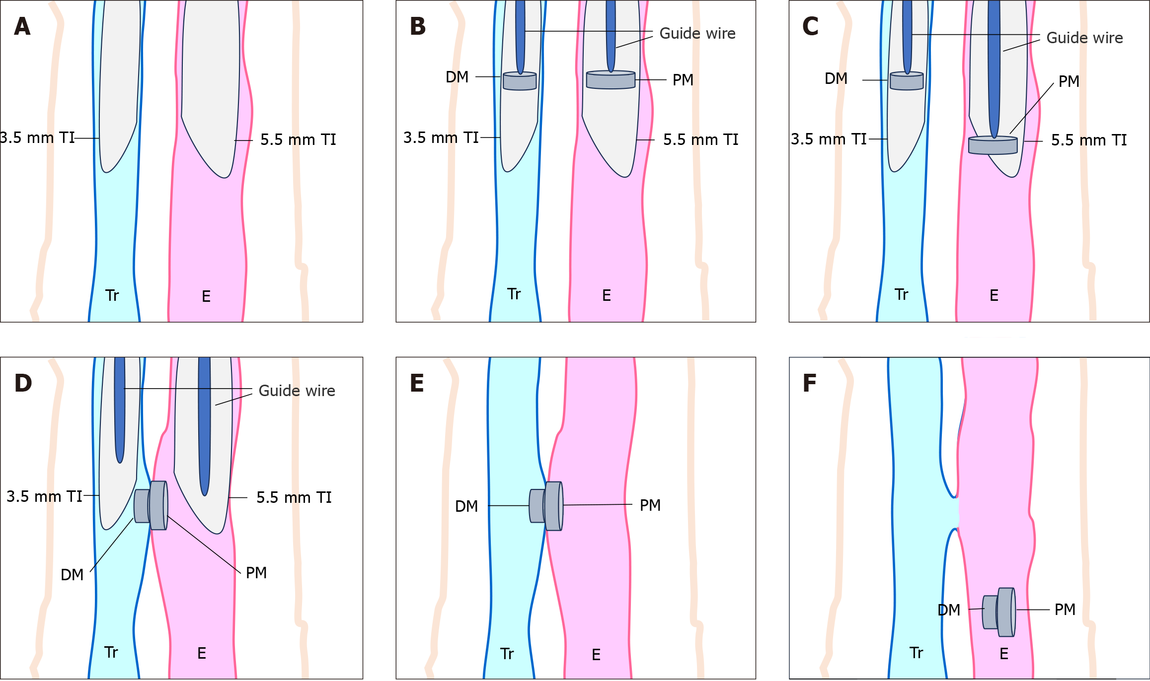
Figure 1 Schematic of the modified magnetic compression technique.
A: Inserting 3.5 mm and 5.5 mm tracheal intubation into the trachea and esophagus respectively; B: Placing the daughter magnet (DM) and parent magnet (PM) inside the tracheal intubation and pushing them to the intubation's end using a guide wire; C: Gently pushing the PM towards the end using the guide wire; D: Under the influence of magnetic force, the DM and PM attract each other, detach from tracheal intubation, and adhere to the tracheal and esophageal mucosa; E: Removing the tracheal intubation and guide wire; F: Separation of the magnets, entry into the esophagus, and expulsion from the body through the digestive tract. Tr: Trachea; TI: Tracheal intubation; E: Esophagus; DM: Daughter magnet; PM: Parent magnet.
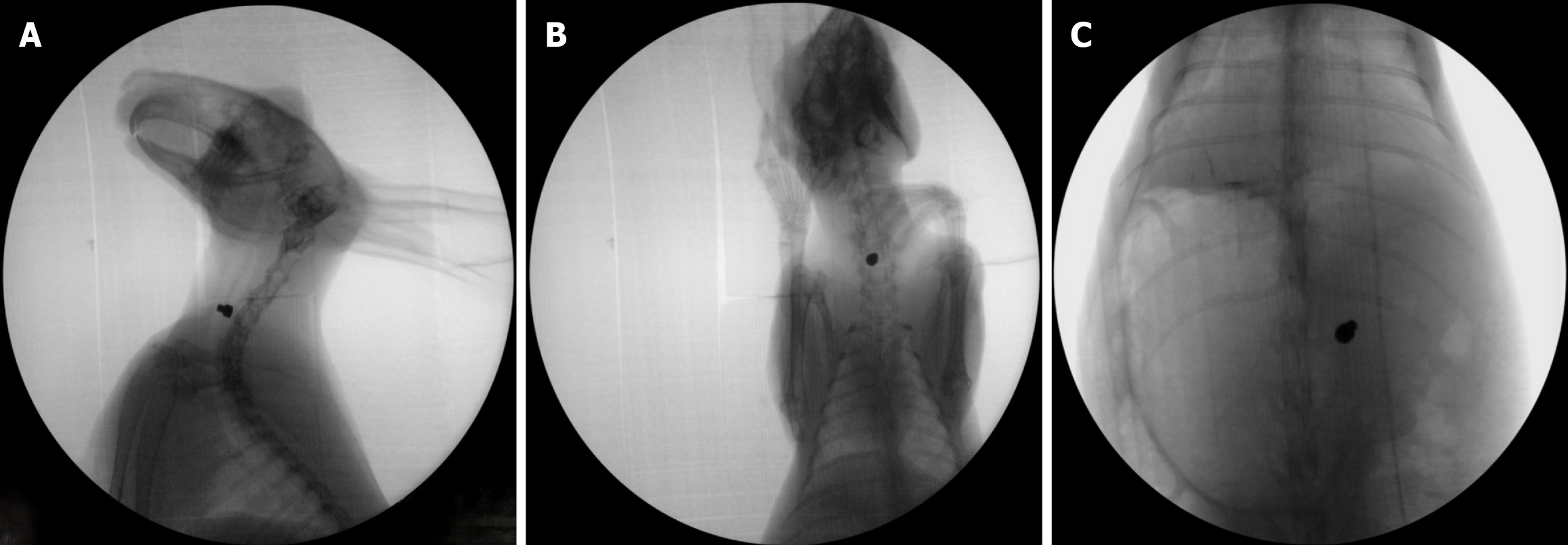
Figure 2 X-ray images of the rabbit neck after magnet implantation.
A: Lateral view; B: Anteroposterior view; C: Magnet entering the digestive tract.
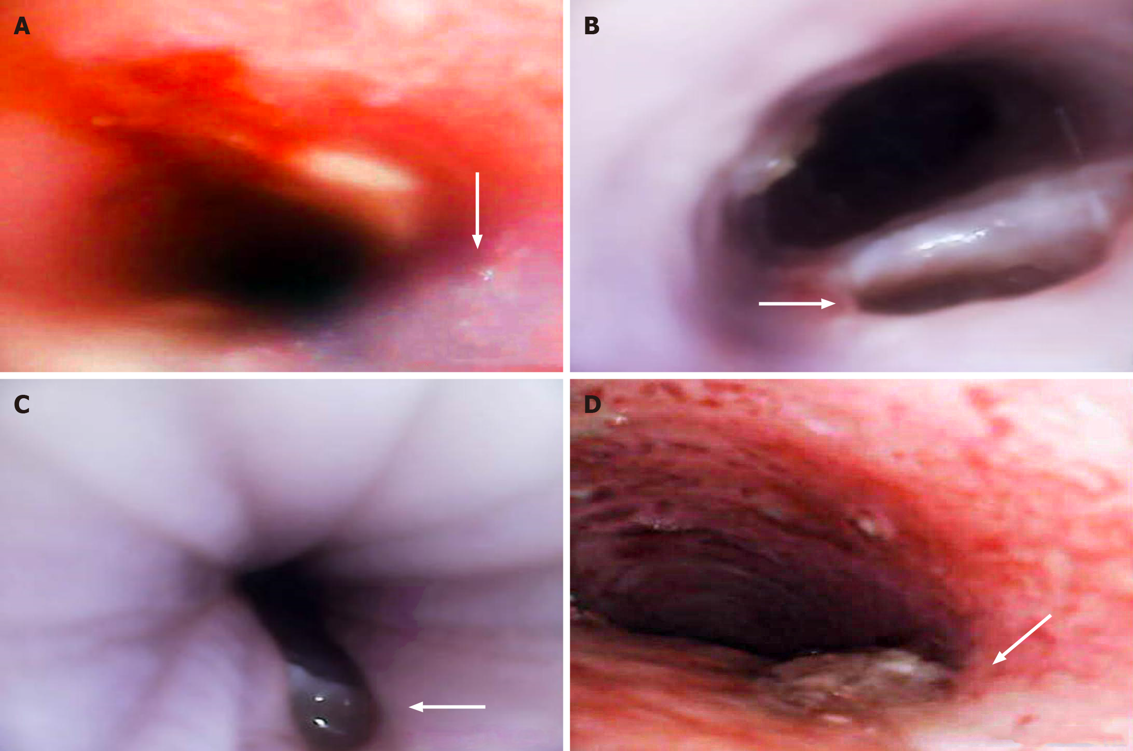
Figure 3 Endoscopic findings after modeling with the surgical modeling technique and modified magnetic compression technique.
A: In the surgical modeling (SM) group, methylene blue was immediate injected into the esophagus, leading to overflow into the trachea (indicated by the arrow); B: 5 d after successful modeling with modified magnetic compression (MMC) technique, the fistula on the tracheal side was observed (indicated by the arrow); C: 5 d after successful modeling with MMC technique, the fistula on the esophageal side was observed (indicated by the arrow); D: 5 d after successful modeling with SM, the fistula and surrounding tracheal mucosa were observed (indicated by the arrow).
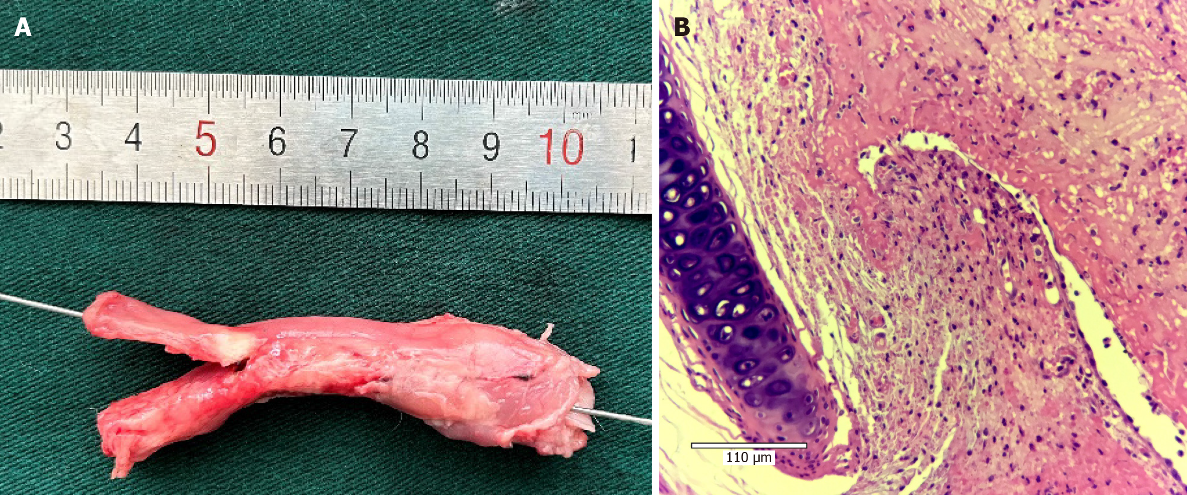
Figure 4 Gross anatomy and pathology of the tracheoesophageal fistula model established by the modified magnetic compression method in rabbits.
A: Longitudinal section of the trachea; B: Longitudinal section of the esophagus; C: Tracheal mucosa around the fistula (hematoxylin & eosin staining, 20 ×).
Figure 5 Gross anatomy and pathology of the tracheoesophageal fistula model established by the surgical method in rabbits.
A: Guidewire inserted from the tracheal side, allowing access to the esophagus through the fistula; B: Tracheal mucosa around the fistula (hematoxylin & eosin staining, 20 ×).
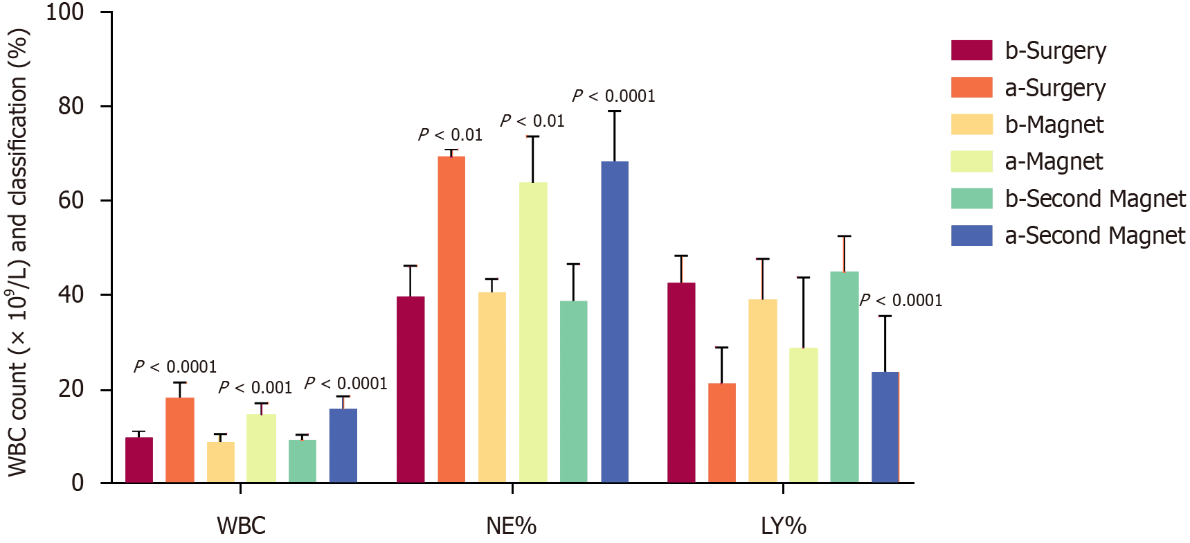
Figure 6 Changes in peripheral blood white blood cell counts and classification in rabbits before and after modeling using different methods.
b-Surgery: Premodeling-surgical method (SM); a-Surgery: Postmodeling-SM; b-Magnet: Premodeling-modified magnetic compression (MMC); a-Magnet: Postmodeling-MMC; b-Second Magnet: Premodeling-second-round MMC; a-Second Magnet: Postmodeling-second-round MMC. P values represent comparisons with premodeling within the same method. WBC: White blood cell; NE%: Neutrophil%; LY%: Lymphocyte%.
- Citation: Meng H, Nan FY, Kou N, Hong QY, Lv MS, Li JB, Zhang BJ, Zou H, Li L, Wang HW. Establishment of acquired tracheoesophageal fistula using a modified magnetic compression technique in rabbits and its postmodeling evaluation. World J Gastrointest Surg 2024; 16(5): 1385-1394
- URL: https://www.wjgnet.com/1948-9366/full/v16/i5/1385.htm
- DOI: https://dx.doi.org/10.4240/wjgs.v16.i5.1385


