Copyright
©The Author(s) 2019.
World J Gastrointest Endosc. Dec 16, 2019; 11(12): 548-560
Published online Dec 16, 2019. doi: 10.4253/wjge.v11.i12.548
Published online Dec 16, 2019. doi: 10.4253/wjge.v11.i12.548
Figure 1 Magnetic compression anastomosis for an esophageal atresia[8].
A: The device of the catheter-mounted magnet; B: Radiograph of the initial position of the devices (the proximal magnet is inserted from the mouth, and the distal magnet is inserted during gastrostomy); C: Radiograph of the devices after the union of the magnets; D: Esophagogram of the distal passage with stenosis and without leak. Used with permission from Springer Nature.
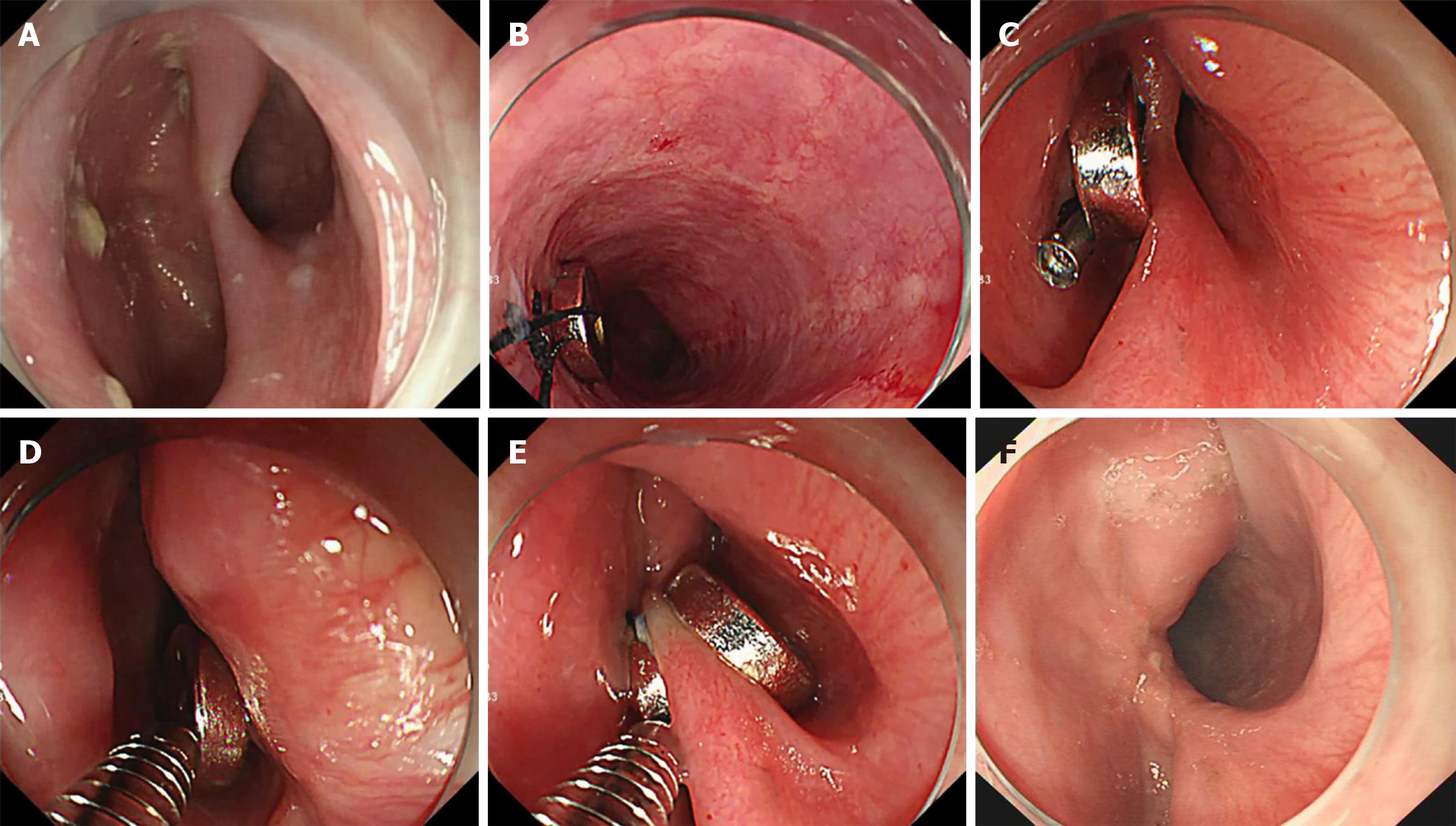
Figure 2 Magnetic compression anastomosis for a Zenker diverticulum[13].
A: Retained diverticulum after endoscopic “clip and cut” diverticulotomy; B: The first magnet with string attached is fixed by clipping into the distal esophagus; C: The second magnet with string attached is fixed to the base of the diverticulum using the same technique; D: The first magnet is pulled back by the releasing device of the endoclip under direct observation; E: The two magnets are coupled together, sandwiching the septum; F: Improvement of the diverticulum. Used with permission from Georg Thieme Verlag KG.
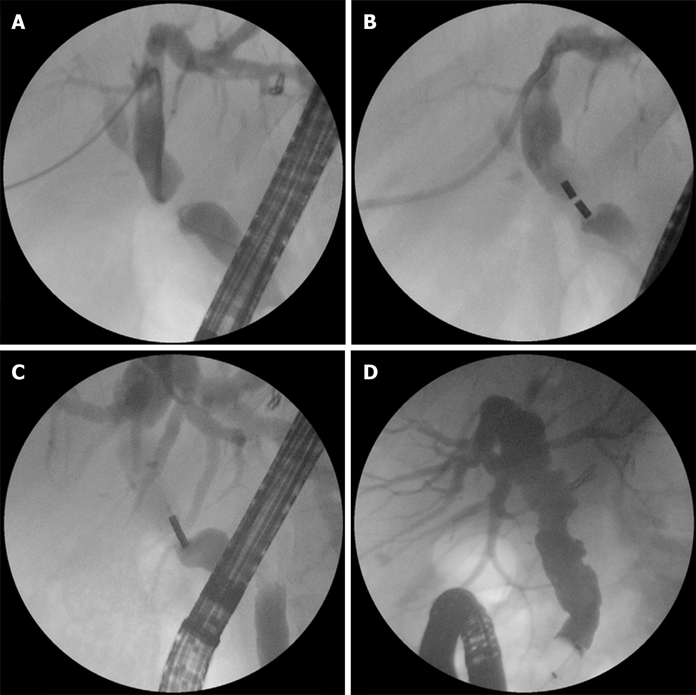
Figure 4 Magnetic compression anastomosis for biliary obstruction[34].
A: Simultaneous percutaneous and balloon-occluded cholangiography shows the details of biliary obstruction; B: Two magnets were placed in the two sides of the obstruction (through the percutaneous transhepatic biliary drainage tract and endoscopic retrograde cholangiopancreatography, respectively); C: The coupling of the two magnets together and recanalization with stricture were achieved; D: Complete resolution of the stricture was achieved after periodical balloon dilation and insertion of multiple plastic biliary stents. Used with permission from Elsevier.
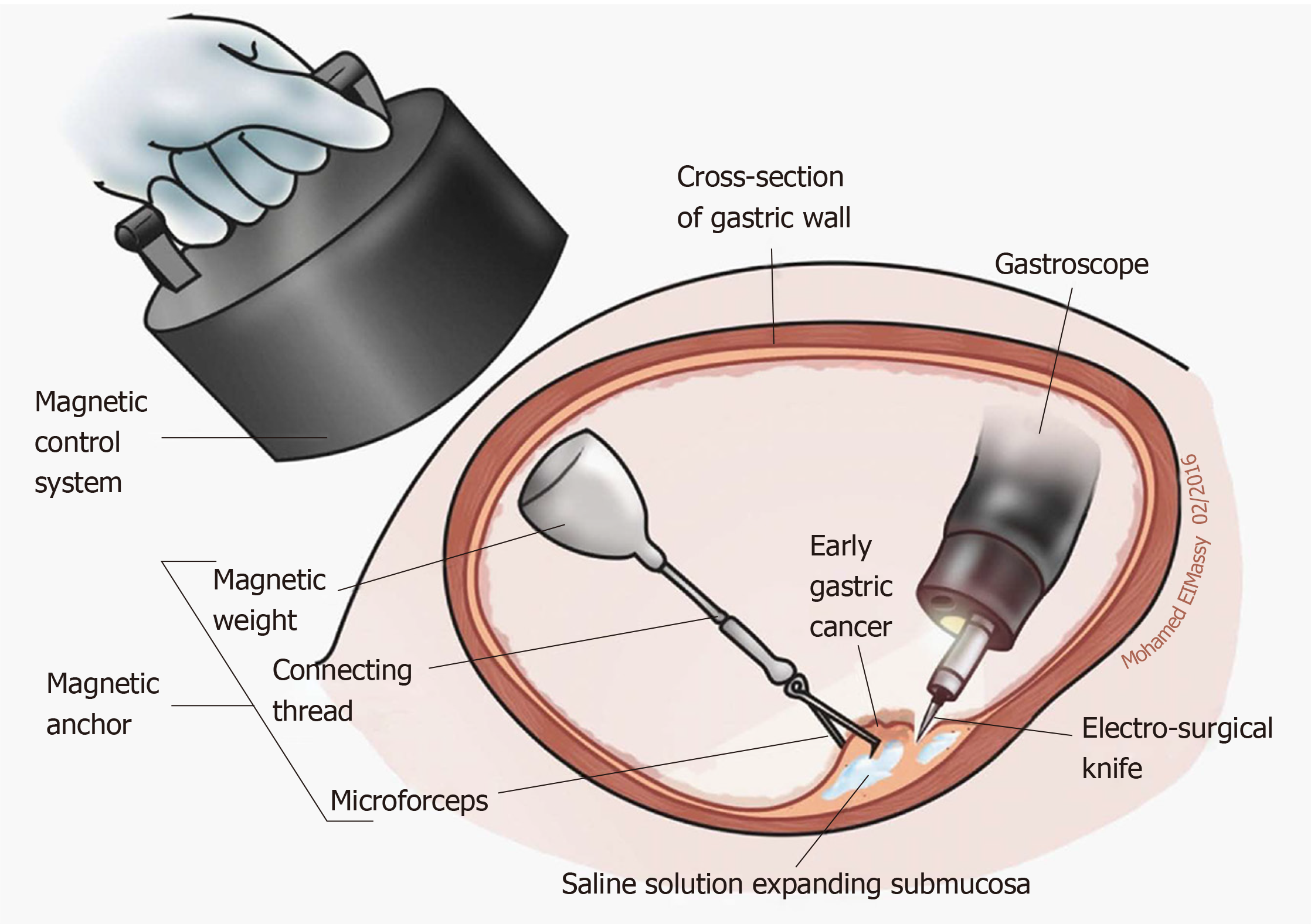
Figure 6 Application diagram of magnetic anchor guided endoscopic submucosal dissection[56].
A small internal permanent magnet is attached to the edge of a partially dissected lesion, while a large external permanent magnet is applied for retraction (an electromagnetic control system can also be selected). Used with permission from Baishideng Publishing Group Inc.
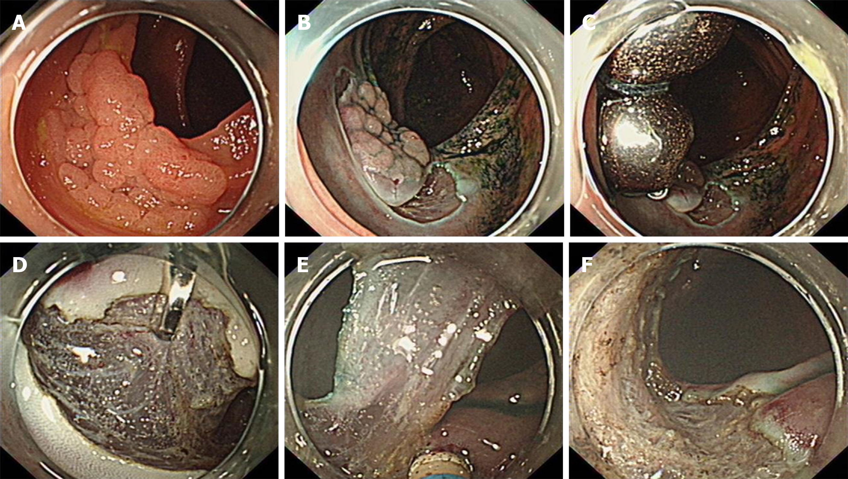
Figure 7 Magnetic bead-assisted endoscopic submucosal dissection for a lesion in the ascending colon.
A: The lesion in the ascending colon; B: The submucosal layer was unclear after partial dissection; C: Application of two magnetic bead systems into the edge of the partially dissected lesion; D, E: The submucosal layer was adequately exposed for precise dissection; F: The mucosal defect after complete resection.
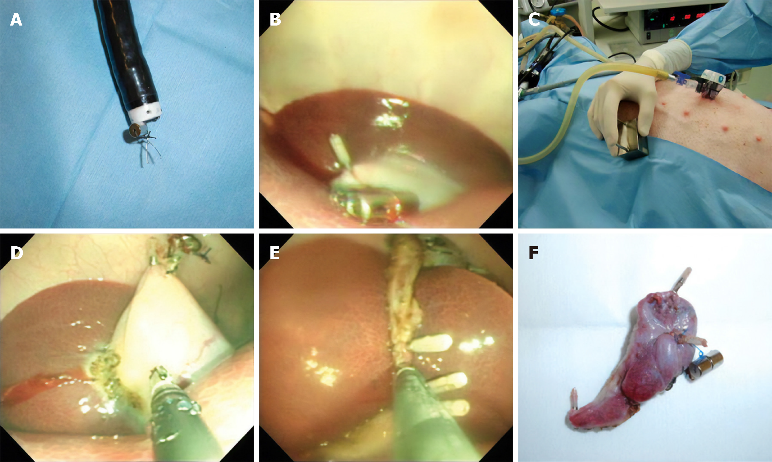
Figure 8 Transvaginal endoscopic cholecystectomy using a simple magnetic traction system in a porcine model[70].
A: a small internal magnet was fixed to endoscopically deployed clips; B: the small magnet was attached to the apex of the gallbladder fundus; C: An external handled magnet was used for traction; D: the gallbladder was dissected from liver using hot claw forceps with the help of the magnetic traction system; E: The cystic duct and artery were ligated and dissected with the help of endoscopic clips; F: The dissected gallbladder. Used with permission from Taylor & Francis.
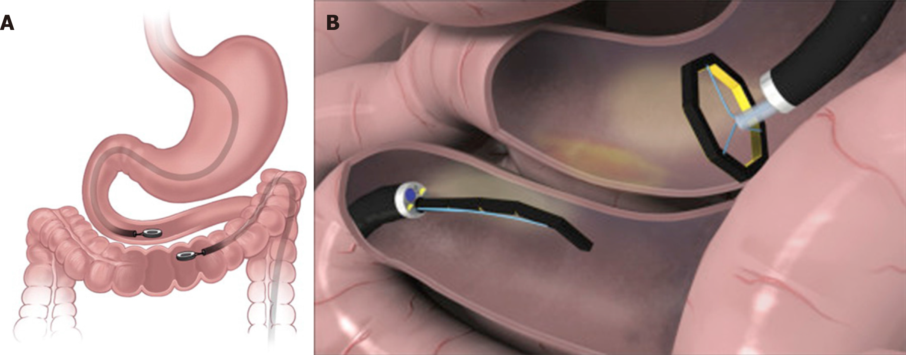
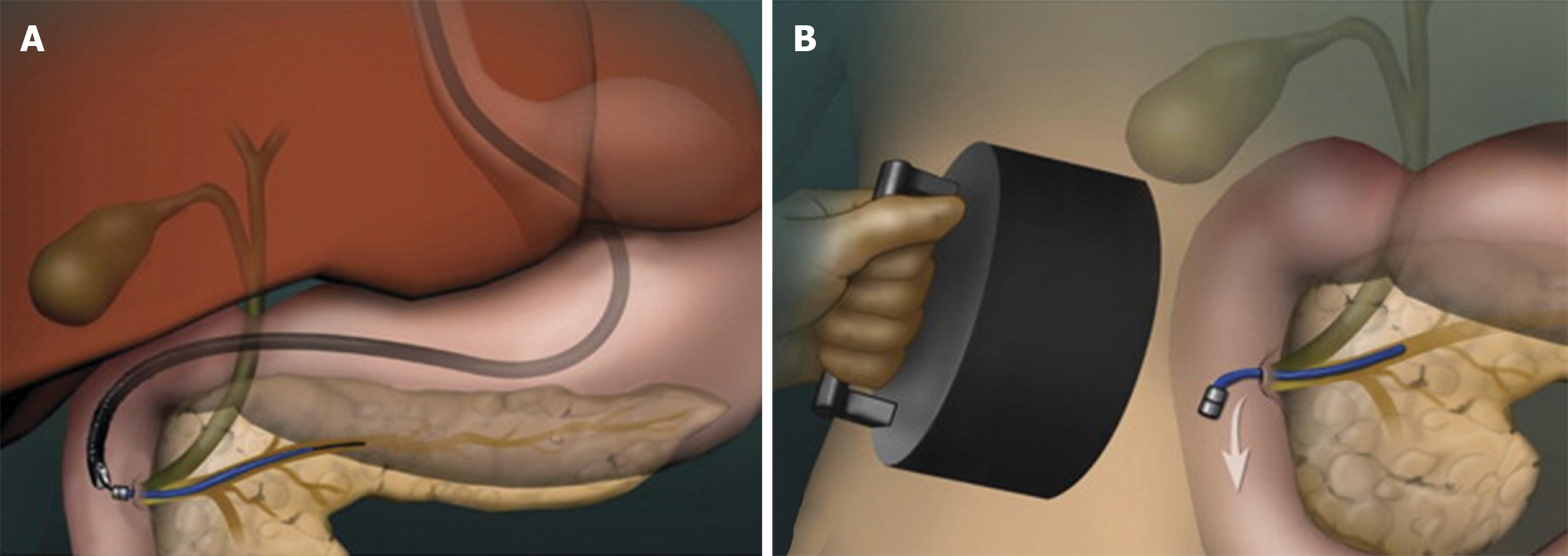
Figure 9 Magnetic pancreaticobiliary stents and retrieval system[86].
A: endoscopic placement of a magnetic stent; B: stent retrieval using a large external magnet. Used with permission from Elsevier.
- Citation: Hu B, Ye LS. Endoscopic applications of magnets for the treatment of gastrointestinal diseases. World J Gastrointest Endosc 2019; 11(12): 548-560
- URL: https://www.wjgnet.com/1948-5190/full/v11/i12/548.htm
- DOI: https://dx.doi.org/10.4253/wjge.v11.i12.548


