Copyright
©The Author(s) 2020.
World J Hepatol. Jul 27, 2020; 12(7): 406-412
Published online Jul 27, 2020. doi: 10.4254/wjh.v12.i7.406
Published online Jul 27, 2020. doi: 10.4254/wjh.v12.i7.406
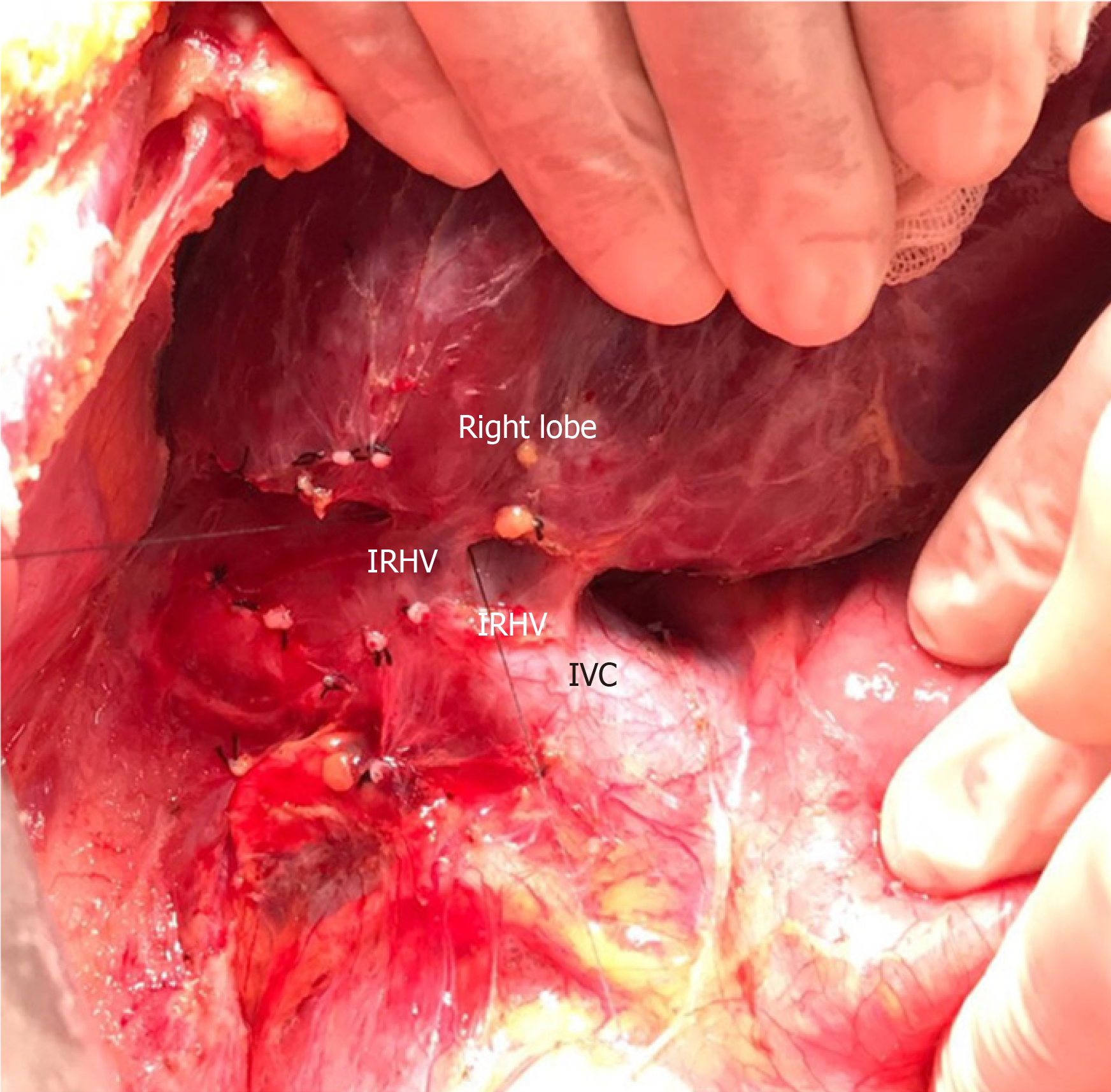
Figure 1 Dissection plan between the right lobe of the liver and inferior vena cava.
Intraoperative view of two inferior right hepatic veins draining the right lobe posterior sector. IRHV: Inferior right hepatic vein; IVC: Inferior vena cava.
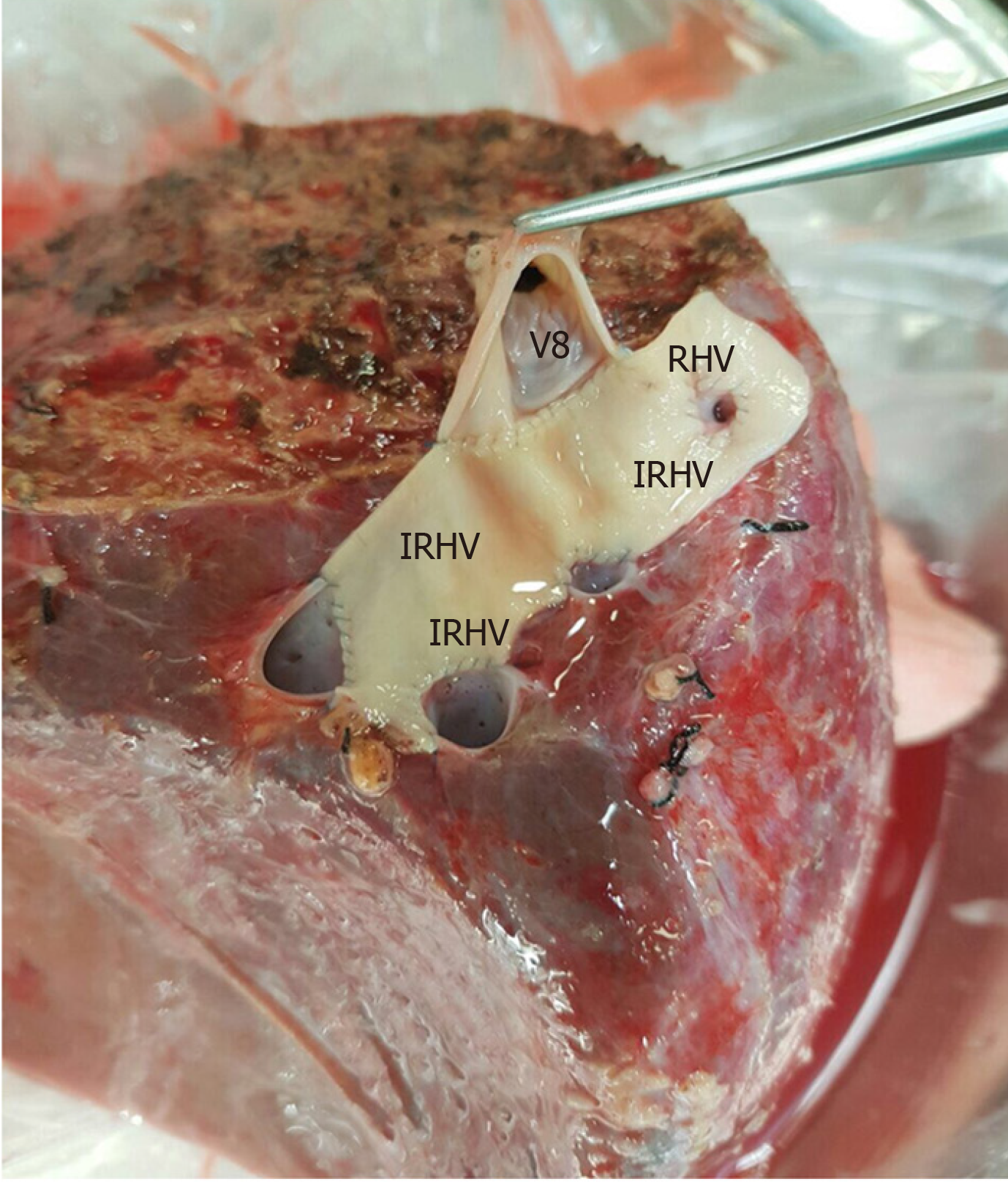
Figure 2 The cryopreserved aortic vascular graft patch was placed between the four orifices as a quilt.
After that the segment 8 hepatic vein orifice was extended to the drainage model using a cryopreserved saphenous vein graft. IRHV: Inferior right hepatic vein; V8: 8 vein; RHV: Right hepatic vein.
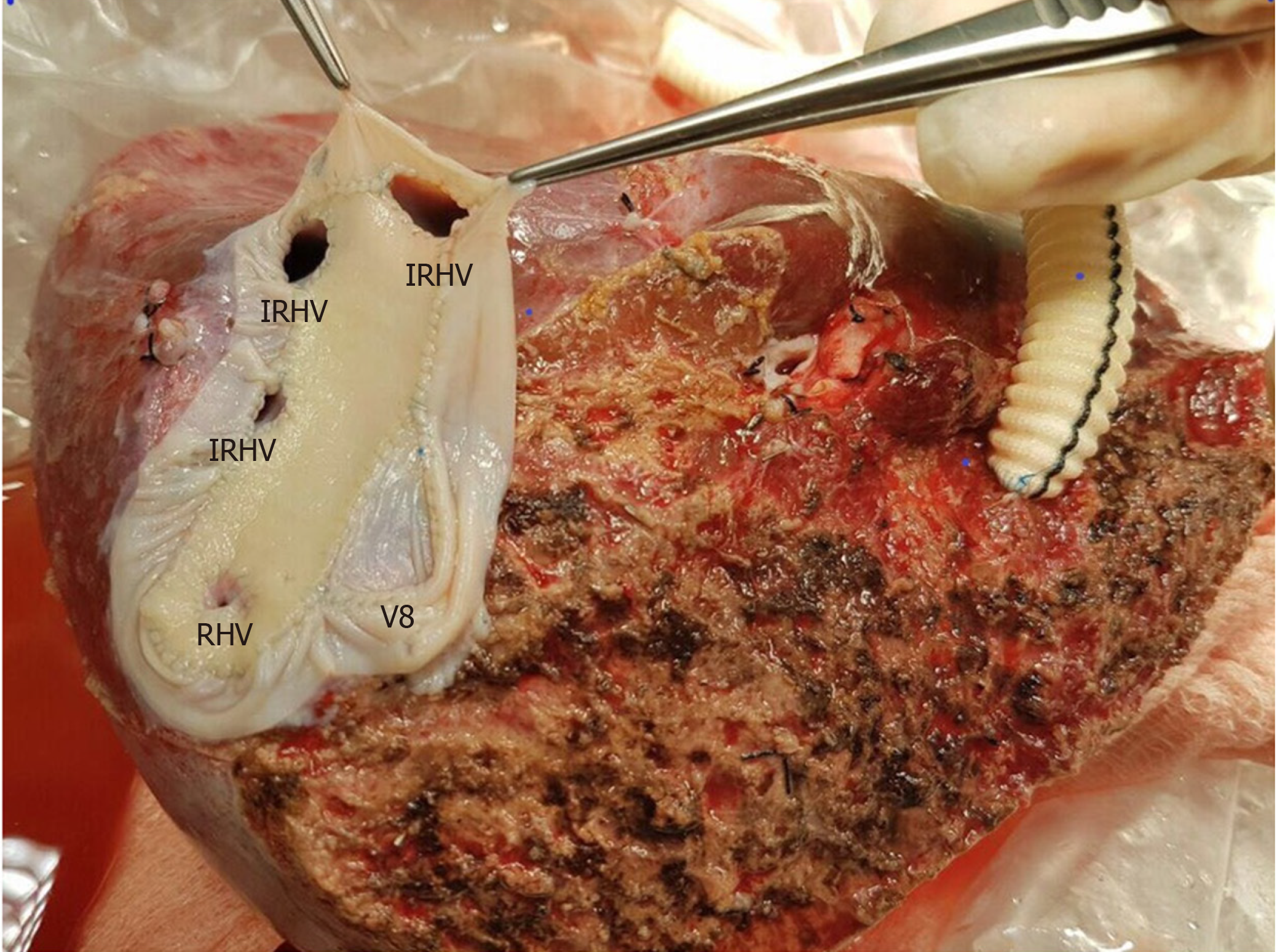
Figure 3 A common large opening drainage model was created using the cryopreserved saphenous vein graft.
IRHV: Inferior right hepatic vein; V8: 8 vein; RHV: Right hepatic vein.
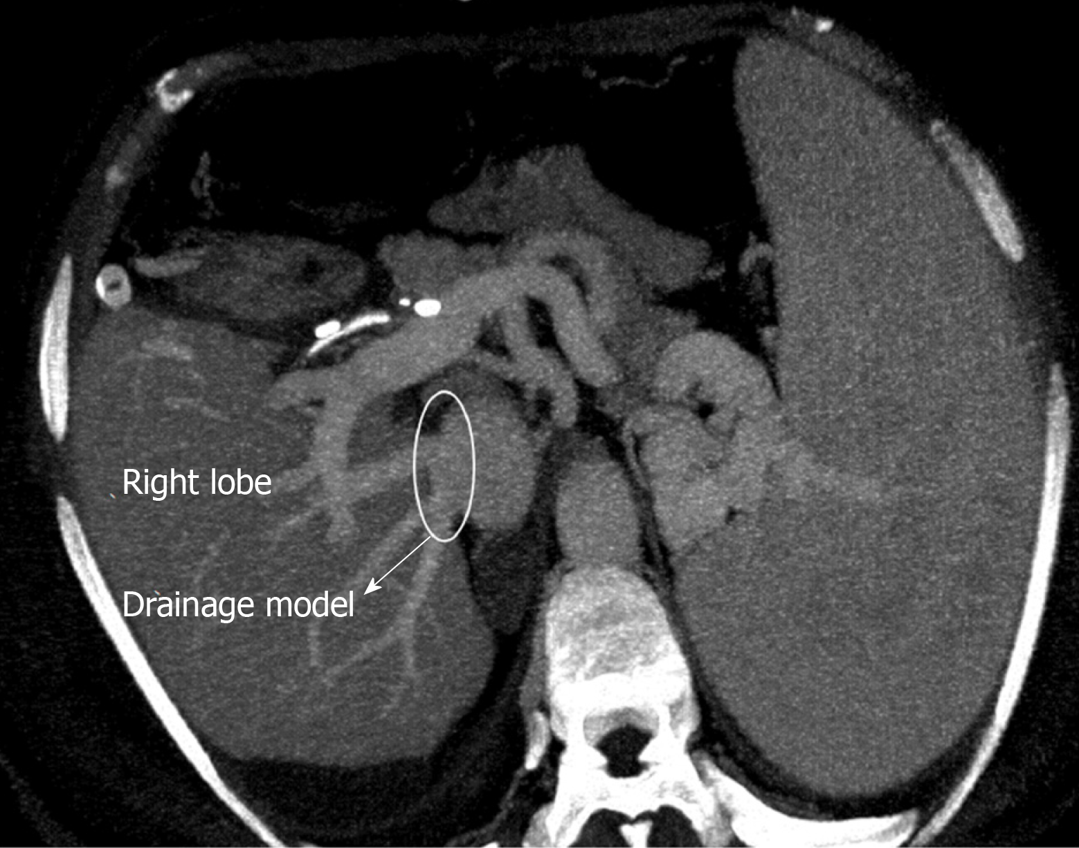
Figure 4 Postoperative contrast axial multidetector computed tomography image shows that the venous drainage model is functional.
- Citation: Demyati K, Akbulut S, Cicek E, Dirican A, Koc C, Yilmaz S. Is right lobe liver graft without main right hepatic vein suitable for living donor liver transplantation? World J Hepatol 2020; 12(7): 406-412
- URL: https://www.wjgnet.com/1948-5182/full/v12/i7/406.htm
- DOI: https://dx.doi.org/10.4254/wjh.v12.i7.406


